

旋转编码器的工作原理以及如何与 Arduino 一起使用
在本教程中,我们将学习旋转编码器的工作原理以及如何在 Arduino 中使用它。您可以观看以下视频或阅读下面的书面教程。
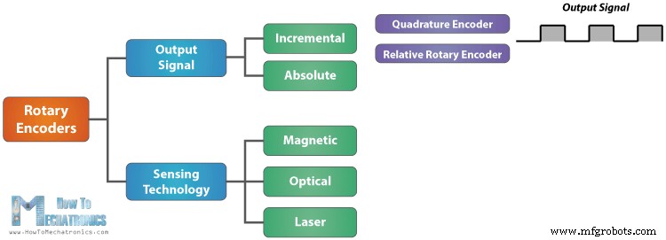
旋转编码器是一种位置传感器,用于确定旋转轴的角位置。它会根据旋转运动产生模拟或数字的电信号。
有许多不同类型的旋转编码器,它们按输出信号或传感技术分类。我们将在本教程中使用的特定旋转编码器是增量旋转编码器,它是测量旋转的最简单的位置传感器。
这种旋转编码器也称为正交编码器或相对旋转编码器,其输出为一系列方波脉冲。
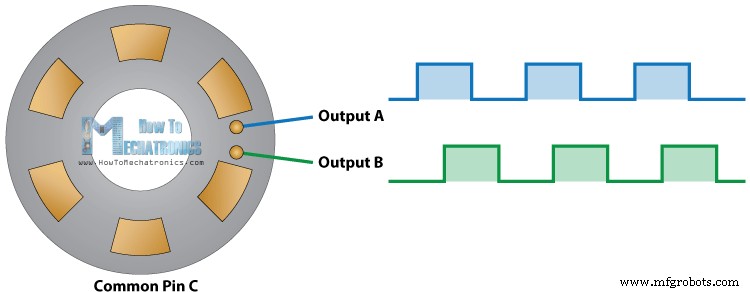
让我们仔细看看编码器,看看它的工作原理。以下是方波脉冲的产生方式:编码器有一个圆盘,其接触区间隔均匀,连接到公共引脚 C 和另外两个独立的触点引脚 A 和 B,如下图所示。
当圆盘开始逐步转动时,A、B脚开始与公共端接触,相应产生两个方波输出信号。
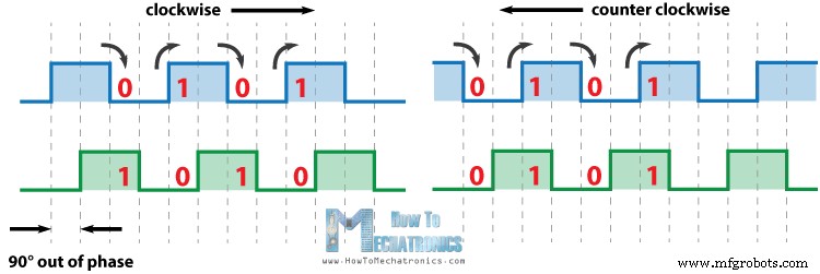
如果我们只计算信号的脉冲数,则两个输出中的任何一个都可用于确定旋转位置。但是,如果我们也想确定旋转方向,我们需要同时考虑这两个信号。
我们可以注意到,两个输出信号的相位相差 90 度。如果编码器顺时针旋转,则输出 A 将领先于输出 B。
因此,如果我们计算每次信号变化时的步数,从高到低或从低到高,我们可以注意到此时两个输出信号具有相反的值。反之亦然,如果编码器逆时针旋转,则输出信号具有相等的值。因此考虑到这一点,我们可以轻松地对控制器进行编程,以读取编码器位置和旋转方向。
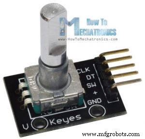
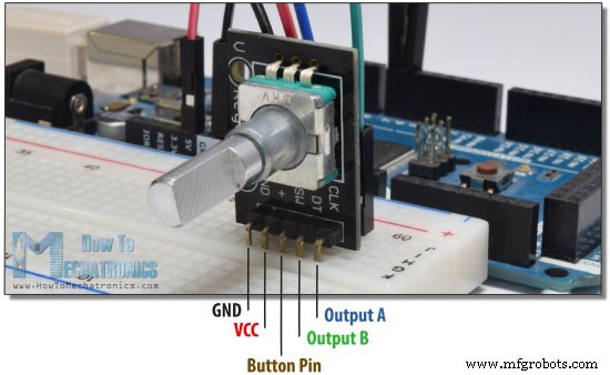
让我们用 Arduino 做一个实际的例子。我将在此示例中使用的特定模块位于分线板上,它有五个引脚。第一个管脚是输出A,第二个管脚是输出B,第三个管脚是Button管脚,当然另外两个管脚是VCC和GND管脚。
我们可以将输出引脚连接到 Arduino Board 的任何数字引脚。
您可以从以下链接获取本 Arduino 教程所需的组件:
这是Arduino代码:
代码说明: 所以首先我们需要定义我们的编码器连接到的引脚,并定义程序所需的一些变量。在设置部分,我们需要将两个引脚定义为输入,启动串行通信以在串行监视器上打印结果,以及读取输出 A 的初始值并将值放入变量 aLastState 中。
然后在循环部分,我们再次读取输出 A,但现在我们将值放入 aState 变量中。因此,如果我们旋转编码器并生成一个脉冲,这两个值将不同,第一个“if”语句将变为 true。紧接着使用第二个“if”语句我们确定旋转方向。如果输出 B 状态与输出 A 状态不同,则计数器将加一,否则将减一。最后,在串口监视器上打印结果后,我们需要用 aState 变量更新 aLastState 变量。
这就是我们在这个例子中所需要的。如果上传代码,启动串行监视器并开始旋转编码器,我们将开始获取串行监视器中的值。我拥有的特定模块每个完整周期计数 30 次。
了解更多:超声波传感器 HC-SR04 和 Arduino - 完整指南
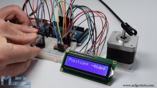
除了这个基本示例之外,我还做了一个使用旋转编码器控制步进电机位置的示例。
下面是这个例子的源代码:
欢迎在下方评论区提出任何问题。概览
旋转编码器的工作原理
旋转编码器Arduino示例
源代码
/*     Arduino Rotary Encoder Tutorial
 *
 *  by Dejan Nedelkovski, www.HowToMechatronics.com
 *
 */

 #define outputA 6
 #define outputB 7

 int counter = 0;
 int aState;
 int aLastState;

 void setup() {
   pinMode (outputA,INPUT);
   pinMode (outputB,INPUT);

   Serial.begin (9600);
   // Reads the initial state of the outputA
   aLastState = digitalRead(outputA);
 }

 void loop() {
   aState = digitalRead(outputA); // Reads the "current" state of the outputA
   // If the previous and the current state of the outputA are different, that means a Pulse has occured
   if (aState != aLastState){
     // If the outputB state is different to the outputA state, that means the encoder is rotating clockwise
     if (digitalRead(outputB) != aState) {
       counter ++;
     } else {
       counter --;
     }
     Serial.print("Position: ");
     Serial.println(counter);
   }
   aLastState = aState; // Updates the previous state of the outputA with the current state
}Code language: Arduino (arduino)示例 2 - 使用旋转编码器控制步进电机
/*     Stepper Motor using a Rotary Encoder
 *
 *  by Dejan Nedelkovski, www.HowToMechatronics.com
 *
 */

 #include <LiquidCrystal.h> // includes the LiquidCrystal Library
 LiquidCrystal lcd(1, 2, 4, 5, 6, 7); // Creates an LC object. Parameters: (rs, enable, d4, d5, d6, d7)

// defines pins numbers
 #define stepPin 8
 #define dirPin  9
 #define outputA 10
 #define outputB 11

 int counter = 0;
 int angle = 0;
 int aState;
 int aLastState;

void setup() {
  // Sets the two pins as Outputs
  pinMode(stepPin,OUTPUT);
  pinMode(dirPin,OUTPUT);
  pinMode (outputA,INPUT);
  pinMode (outputB,INPUT);

  aLastState = digitalRead(outputA);
  lcd.begin(16,2); // Initializes the interface to the LCD screen, and specifies the dimensions (width and height) of the display }

}
void loop() {

  aState = digitalRead(outputA);

  if (aState != aLastState){
     if (digitalRead(outputB) != aState) {
       counter ++;
       angle ++;
       rotateCW();
     }
     else {
       counter--;
       angle --;
       rotateCCW();
     }
     if (counter >=30 ) {
      counter =0;
     }

     lcd.clear();
     lcd.print("Position: ");
     lcd.print(int(angle*(-1.8)));
     lcd.print("deg");
     lcd.setCursor(0,0);

   }
  aLastState = aState;
}

void rotateCW() {
  digitalWrite(dirPin,LOW);
    digitalWrite(stepPin,HIGH);
    delayMicroseconds(2000);
    digitalWrite(stepPin,LOW);
    delayMicroseconds(2000);
}
void rotateCCW() {
  digitalWrite(dirPin,HIGH);
    digitalWrite(stepPin,HIGH);
    delayMicroseconds(2000);
    digitalWrite(stepPin,LOW);
    delayMicroseconds(2000);
}
Code language: Arduino (arduino)
制造工艺
- C# 队列示例:什么是 C# 队列以及如何使用?
- 使用 Arduino 和 MPU6050 控制伺服电机
- 带旋转编码器的DIY简易测量轮
- u-blox LEA-6H 02 GPS 模块,带有 Arduino 和 Python
- 如何使用 DHT11 在 Blynk 上读取温度和湿度
- 使用热敏电阻有多容易?!
- 如何用 Arduino 制作音乐
- 如何在 Arduino 中使用 NMEA-0183
- 如何在 Arduino 中使用 Modbus
- 使用 Arduino 和 BitVoicer 服务器进行语音识别
- 带有 Arduino 和 Python 的人工智能助手机器人
- 使用 Raspberry Pi 和 Arduino 的网络控制 LED 动画