

Joy Robot (Robô Da Alegria)
组件和用品
 |
| × | 1 | |||
 |
| × | 1 | |||
 |
| × | 6 | |||
| × | 2 | ||||
| × | 1 | ||||
| × | 1 | ||||
| × | 4 | ||||
 |
| × | 1 | |||
| × | 2 | ||||
| × | 2 | ||||
 |
| × | 1 | |||
| × | 1 | ||||
 |
| × | 3 |
必要的工具和机器
| ||||
 |
|
应用和在线服务
 |
| |||
 |
| |||
|
关于这个项目
Instructables Wheel 竞赛一等奖,Instructables Arduino 竞赛二等奖,以及 Instructables Design for Kids 挑战赛亚军。感谢所有投票给我们的人!!!
http://www.instructables.com/id/Joy-Robot-Rob%C3%B4-Da-Alegria-Open-Source-3D-Printed-A/
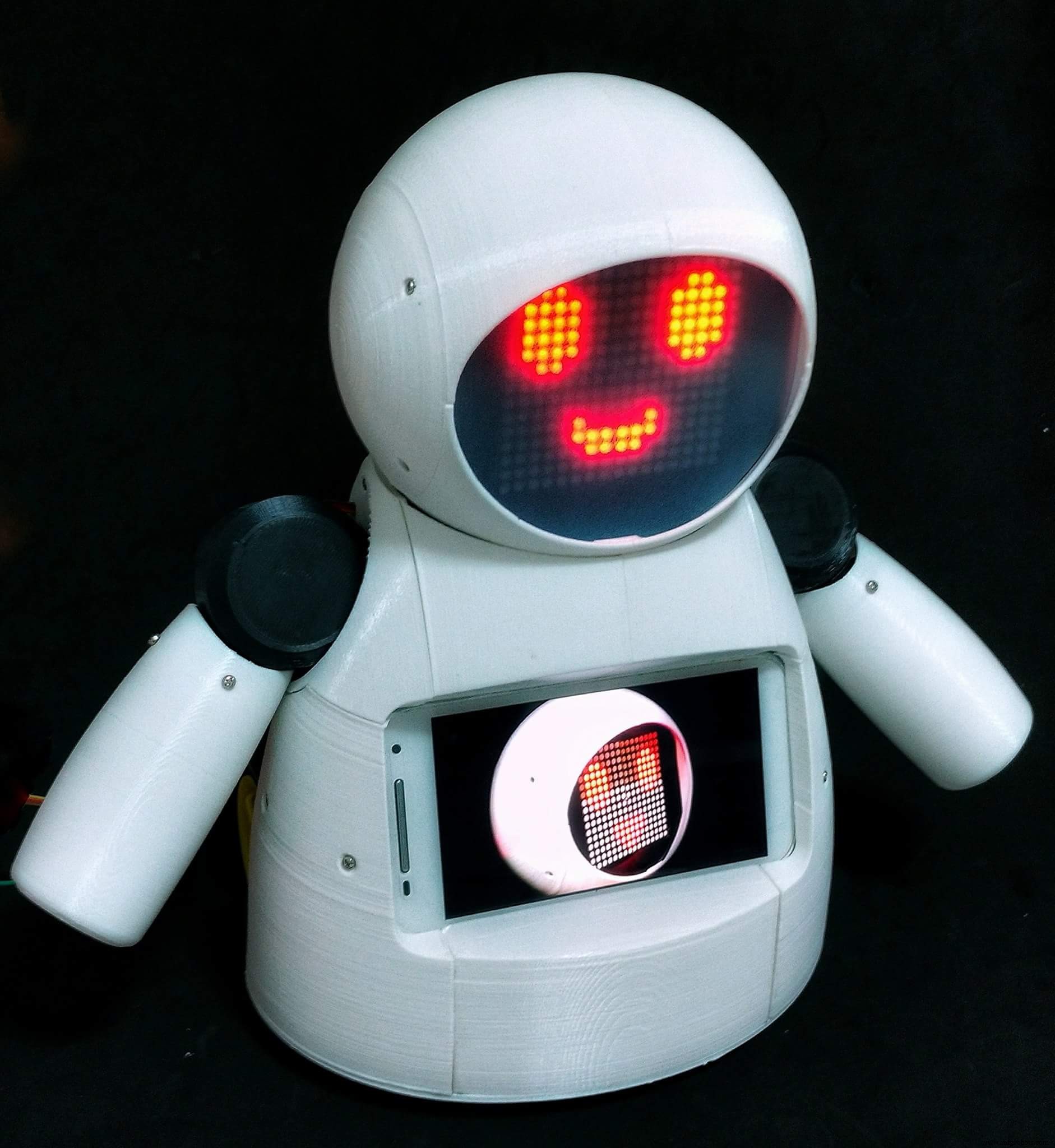
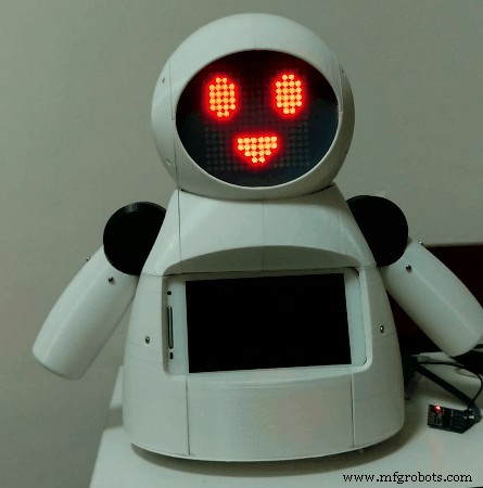
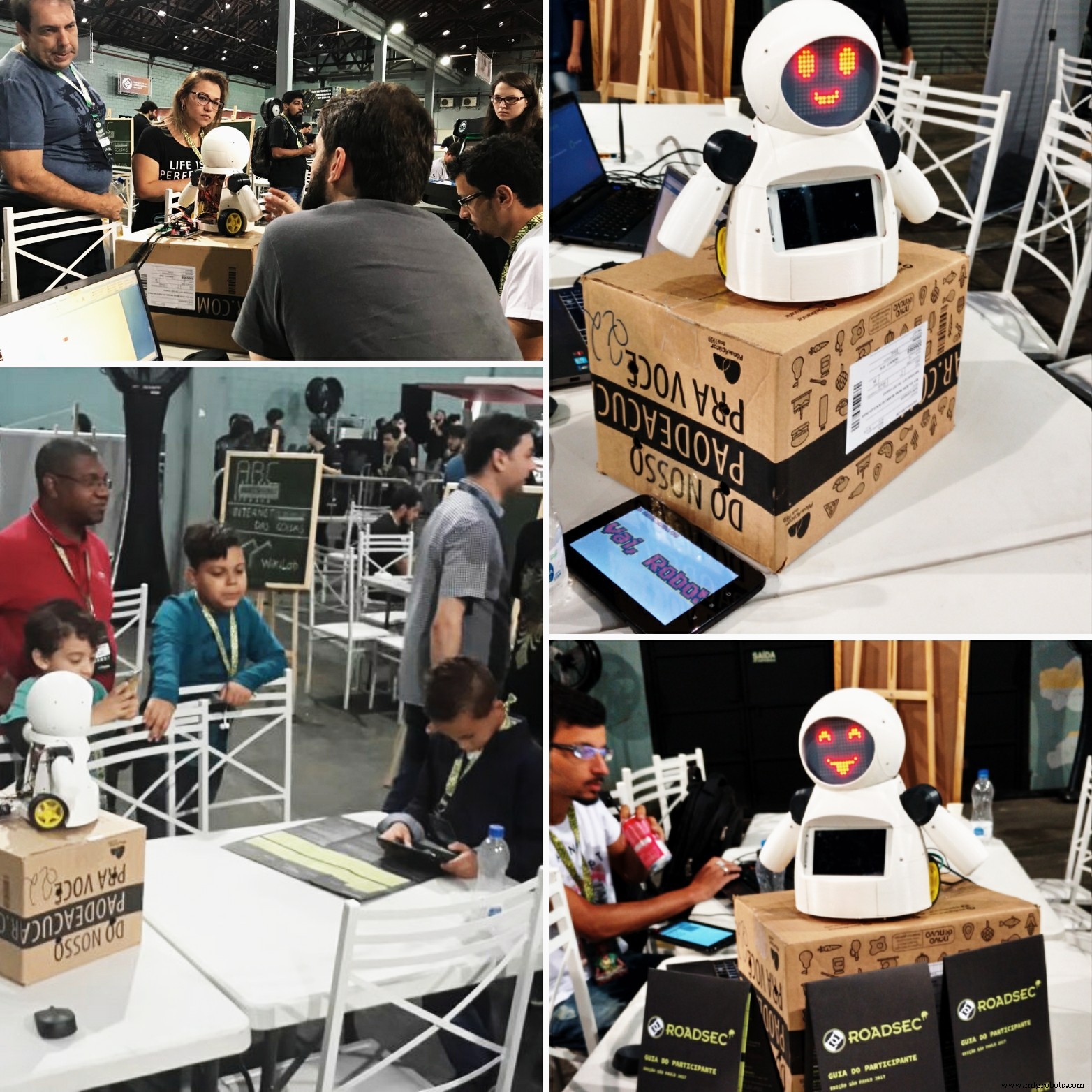
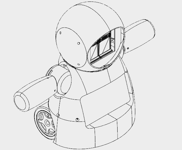
机器人无处不在。从工业应用到水下和太空探索。但我最喜欢的是那些用于娱乐和娱乐的!在这个项目中,一个DIY机器人被设计用于儿童医院的娱乐,给孩子们带来了一些乐趣。该项目专注于分享知识和促进技术创新,以帮助非政府组织在儿童医院开展慈善工作。
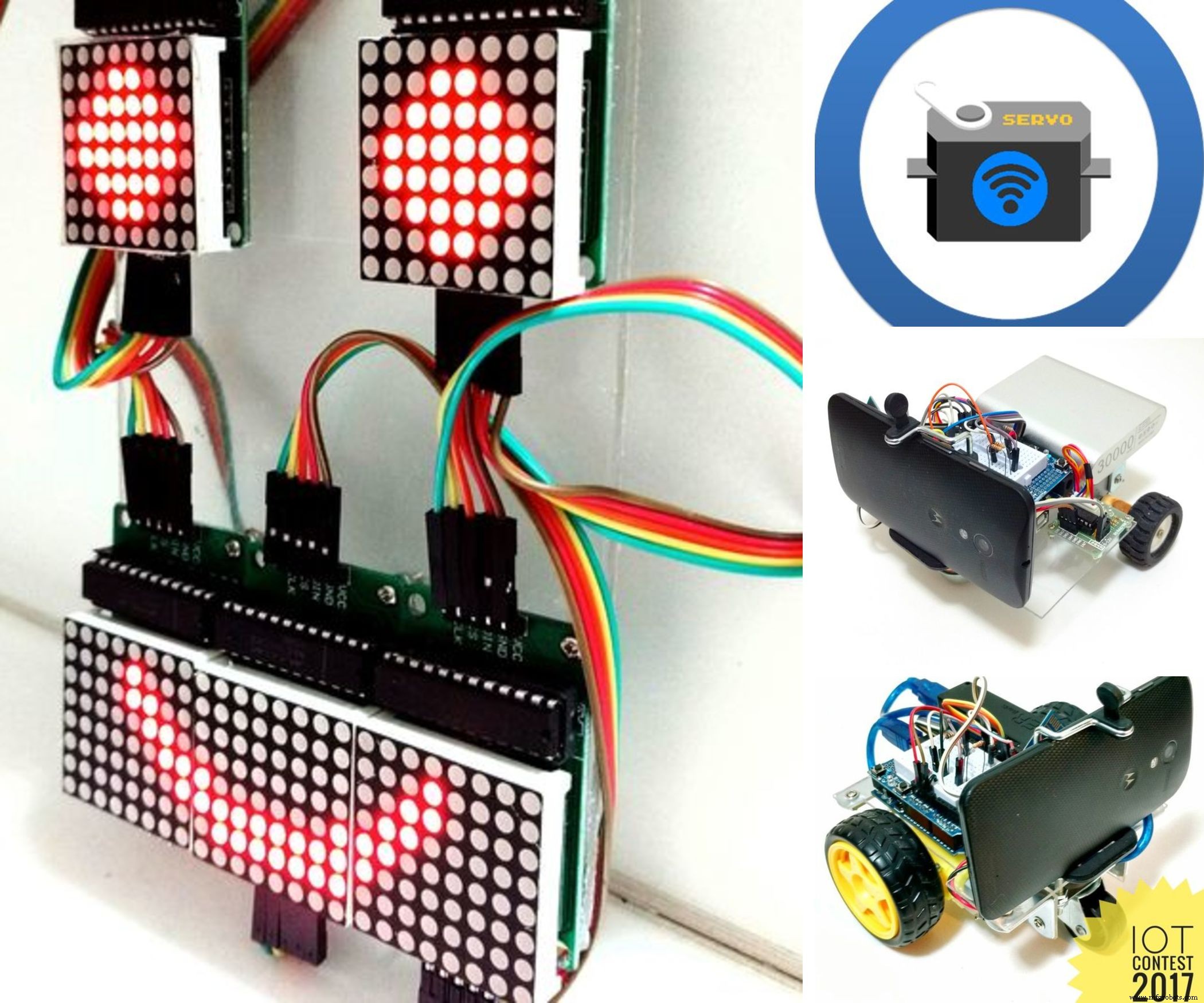
本教程展示了如何使用连接到 ESP8266 Wi-Fi 模块的 Arduino Uno,设计一个远程操作的人形机器人,通过 Wi-Fi 网络进行控制。它使用一些伺服电机形成头部和手臂运动,一些直流电机用于小距离移动,以及由 LED 矩阵制成的面。可以使用 HTML 设计的界面从普通的互联网浏览器控制机器人。 Android智能手机用于将机器人的视频和音频广播到操作员的控制界面。
本教程展示了如何 3D 打印和组装机器人的结构。讲解电子电路,详细Arduino代码,让任何人都可以复制机器人。
用于该机器人的一些技术已经发布在教程中。请看以下教程:
- https://www.instructables.com/id/WiDC-Wi-Fi-Controlled-FPV-Robot-with-Arduino-ESP82/
- https://www.instructables.com/id/Controlling-a-LED-Matrix-Array-With-Arduino-Uno/
- https://www.instructables.com/id/Wi-Servo-Wi-fi-Browser-Controlled-Servomotors-with/
特别感谢参与上述项目的其他团队成员,他们负责本教程中提供的代码的第一个版本:
- 蒂亚戈·法拉什
- 迭戈·奥古斯都
- Yhan Christian
- 赫拉姆·莫雷拉
- 小保罗·德·阿泽维多
- 吉尔赫姆·普波
- 里卡多·卡斯皮罗
- ASEBS
了解有关该项目的更多信息:
- https://hackaday.io/project/12873-rob-da-alegria-joy-robot
- https://www.hackster.io/igorF2/robo-da-alegria-joy-robot-85e178
- https://www.facebook.com/robodaalegria/
你能提供什么帮助?
该项目由团队成员和一些企业的小额捐款资助。如果您喜欢它,您可以通过一些方式帮助我们:
- 投票: 该项目正在参加教程轮子、儿童设计和 Arduino 竞赛。请为我们投票! :D
- 捐赠 :如果您想支持机器人的构建及其未来的改进,您可以向我们发送提示。这些小费将用于购买用品(电子产品、3D 打印、灯丝等),并帮助促进我们在儿童医院的干预措施。您的名字将添加到项目的学分中!您可以在 Thingiverse 平台发送来自我们设计的提示:https://www.thingiverse.com/thing:2765192
- 喜欢 :向我们展示您对我们项目的欣赏程度。在我们记录项目的平台(Facebook、Hackster、Hackaday、Maker Share、Thingiverse...)上给我们一个“赞”。
- 分享 :在您最喜欢的社交媒体网站上分享该项目,以便我们可以覆盖更多人,并激励全球更多的创客。
您是否知道只需 349.99 美元即可购买 Creality CR10mini?使用优惠券代码 cr10mini3d 在 Gearbest 获取它:http://bit.ly/2FZ5OXw
第 1 步:一点点历史...

'Robô da Alegria'('Joy Robot')项目于 2016 年诞生于巴西 Baixada Santista 地区,旨在开发技术并吸引社区参与创客运动。受非政府组织在儿童医院开展的志愿项目的启发,该项目旨在开发一种机器人,使用开放硬件和 apen 软件工具,能够为儿童医院环境带来一点乐趣,并为其他组织的工作做出贡献。
该项目的种子是在 2015 年底播下的。在谈论了由 Baixadas Santista 创业协会 (ASEBS) 推动的技术的创造和发展之后。这是一个理想化的项目,没有奖金,但它提出了一个主题,人们会以利他的方式参与其中,目的是帮助他人。
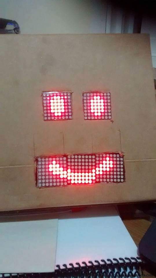
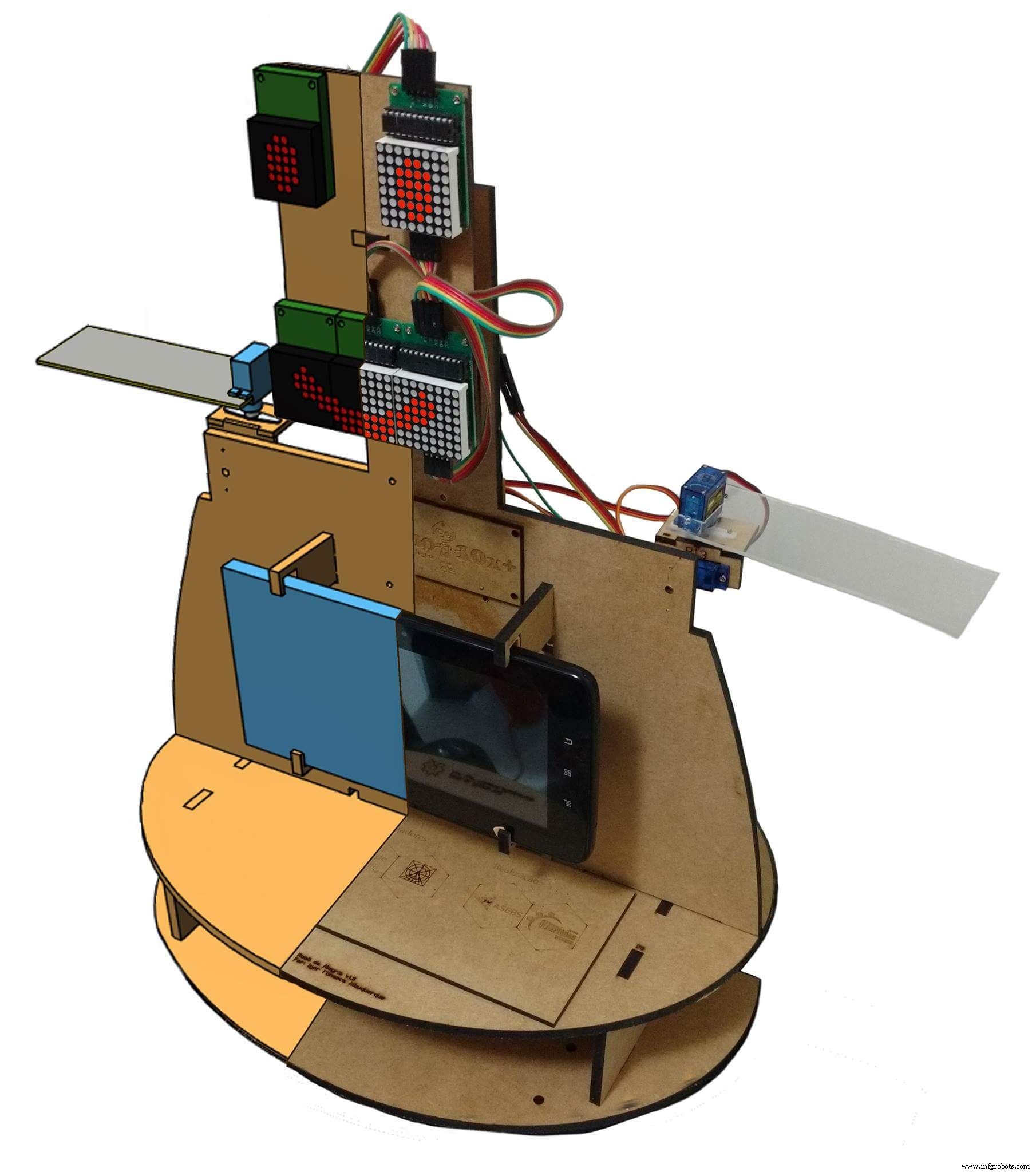
机器人从最初的构想到现在的状态经历了各种各样的转变。从只有一个头,机械眼和眉毛,到现在的人形,进行了多次迭代,测试不同的结构材料和电子设备。从亚克力原型和激光切割 MDF,我们转向了 3D 打印的身体。从由蓝牙控制的两个伺服电机的简单界面,到使用 Wi-Fi 网络的 Web 界面由 6 个伺服电机和 2 个电机 DC 命令组成的主体。
机器人结构完全使用 Fusion 360 进行 3D 打印制作。为了能够在创客空间或制造实验室中生产机器人复制品,在这些地方,打印机的最大使用时间至关重要,机器人的设计被分成几部分每个打印时间少于三个小时。该组零件通过胶合或螺栓连接用于车身安装。
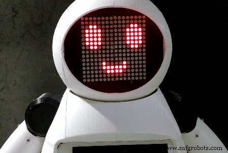
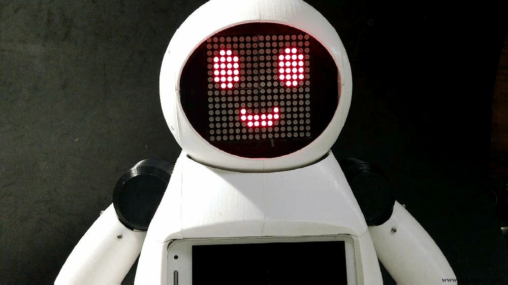
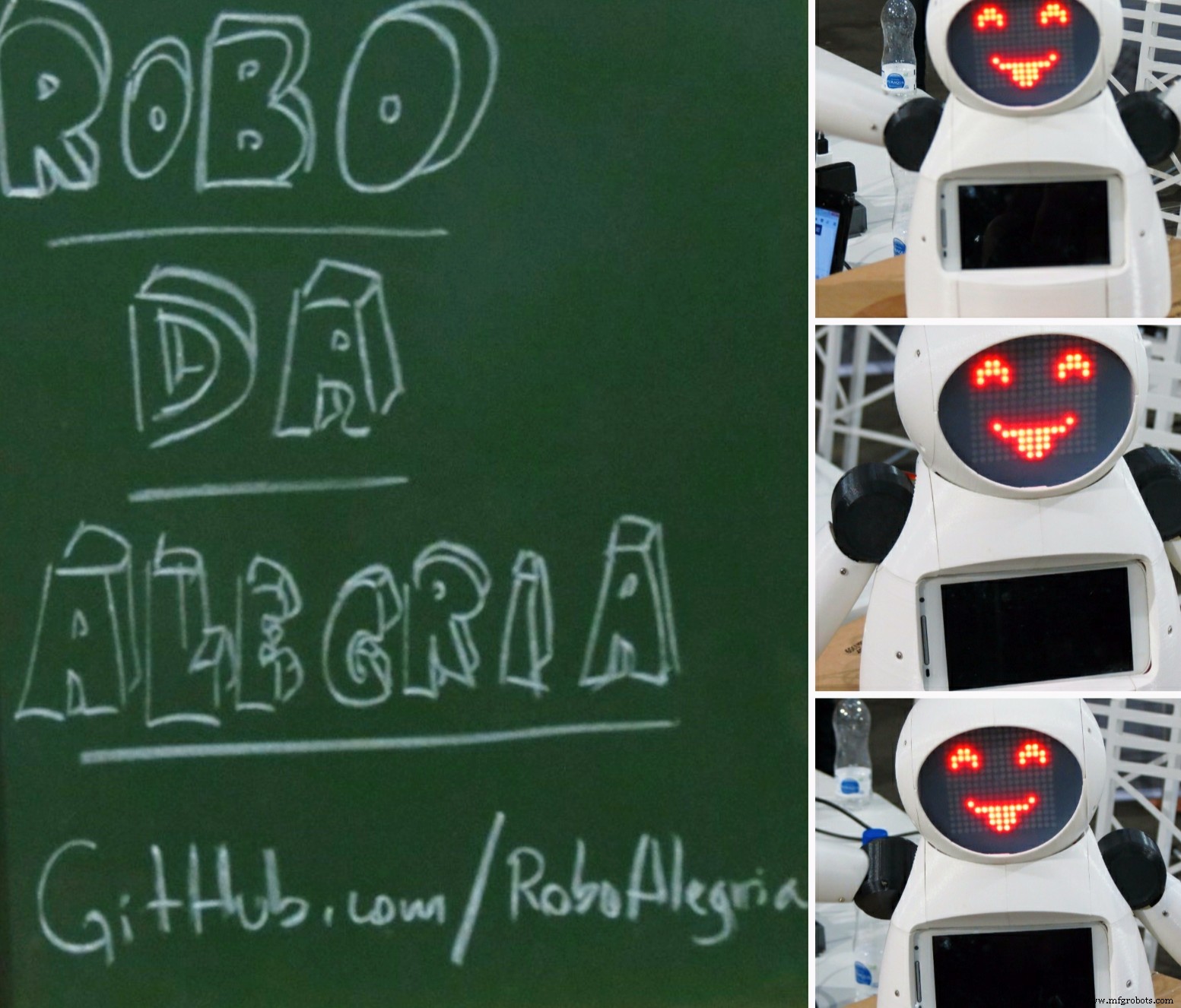
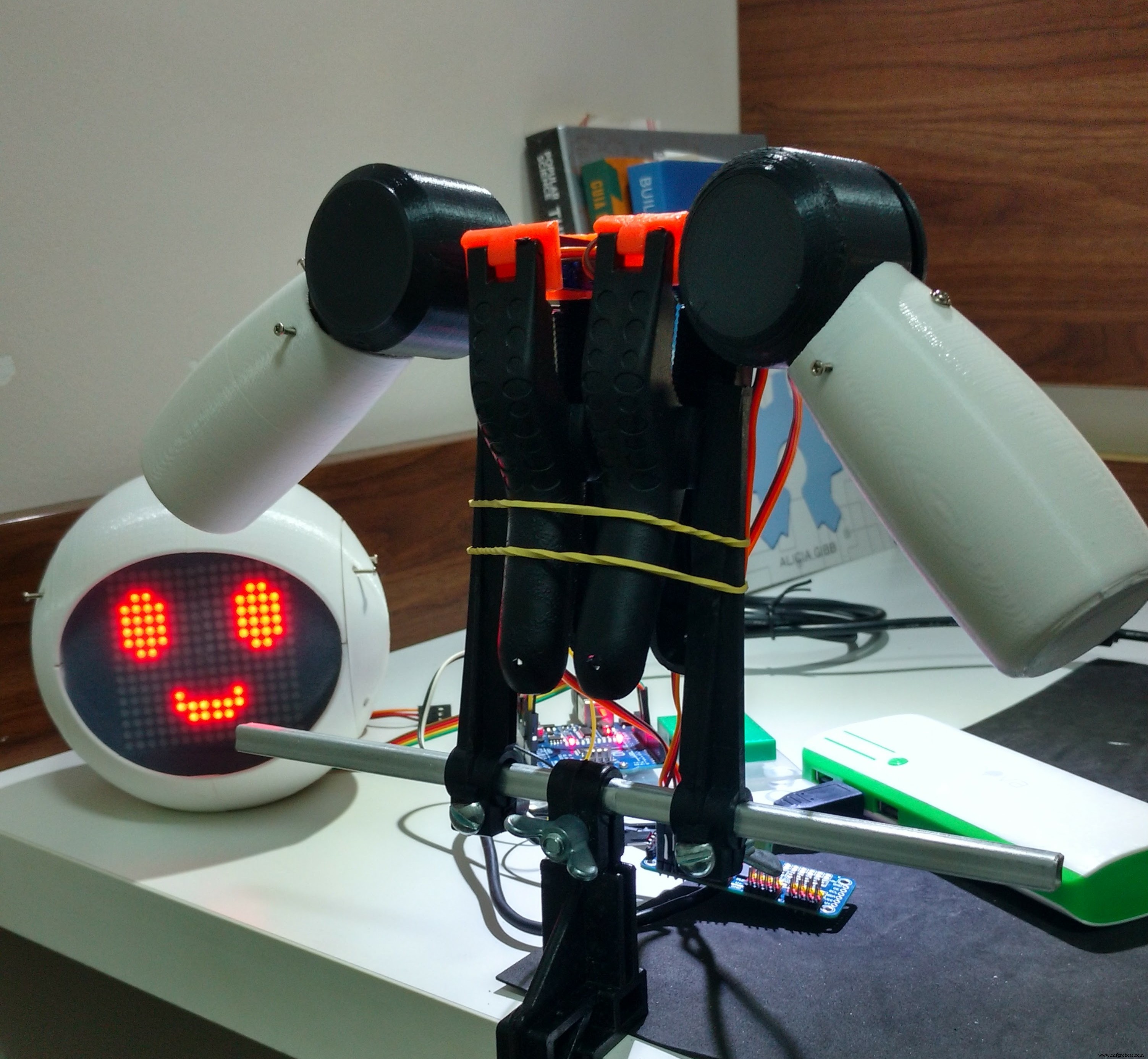
由 LED 阵列组成的面部赋予机器人表达情感的能力。伺服电机驱动的手臂和颈部为小型自动机提供了与用户交互所需的移动性。在机器人的控制中心,Arduino Uno 与所有外围设备接口,包括与 ESP8266 模块的通信,这使用户能够通过连接到同一 Wi-Fi 网络的任何设备来命令表情和动作。
机器人胸前还装有一部智能手机,用于机器人操作者和孩子之间的音频和视频传输。设备屏幕仍可用于与游戏和其他旨在与机器人身体交互的应用程序的交互。
第 2 步:工具和材料

本项目使用了以下工具和材料:
工具:
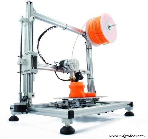
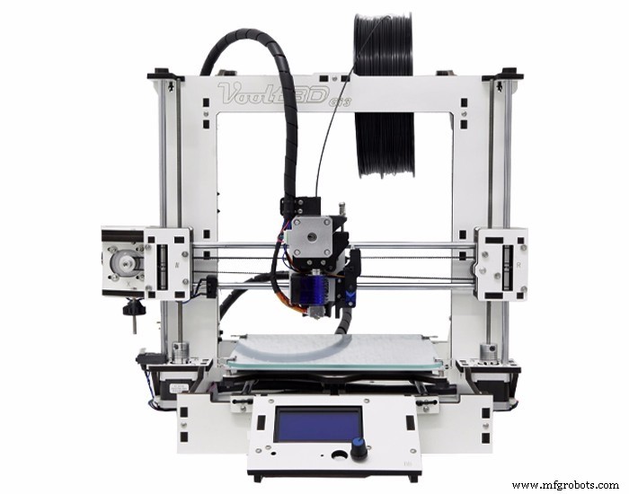
- 3D 打印机 - 机器人的整个身体都是 3D 打印的。建造整个结构需要几个小时的 3D 打印;
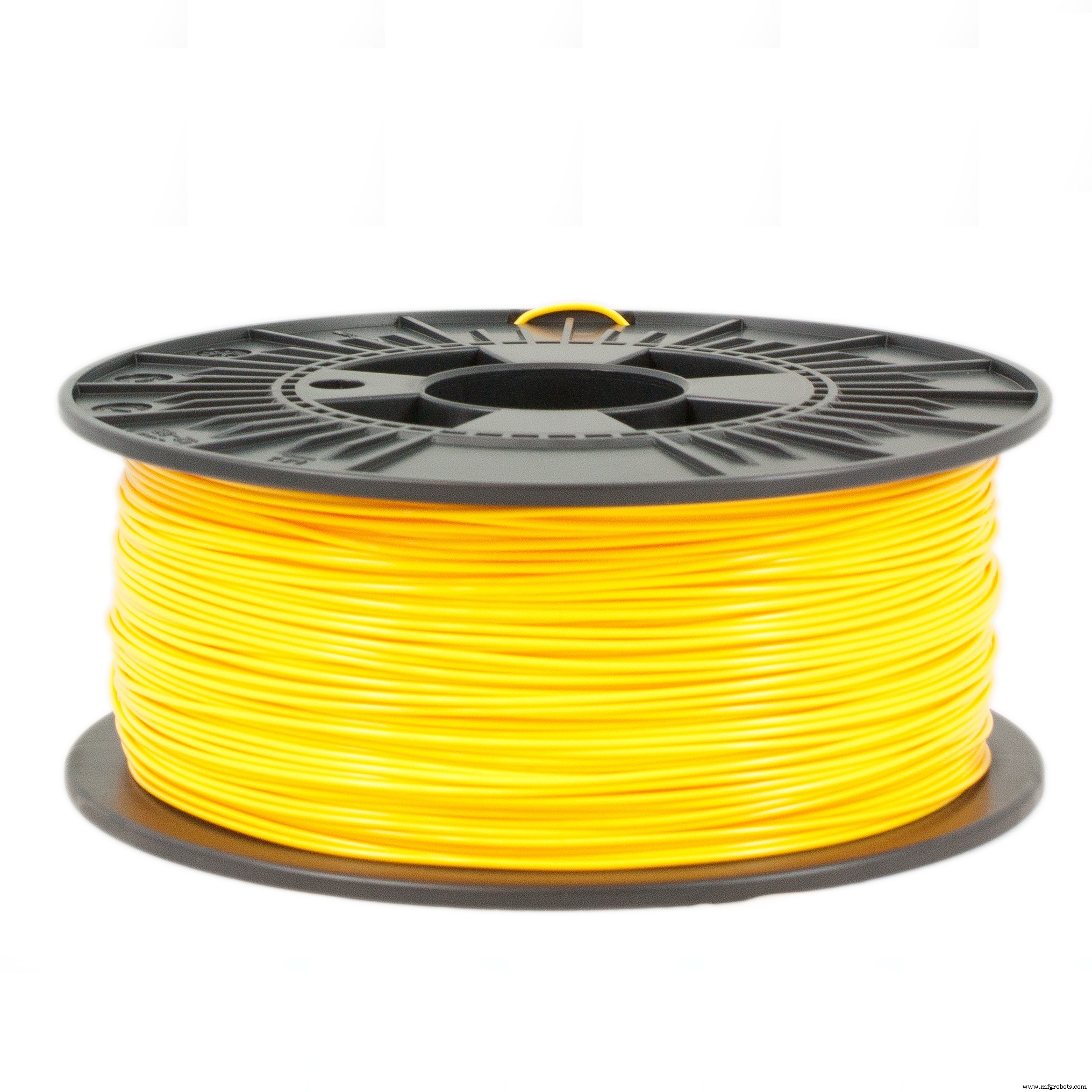
- PLA 灯丝 - 用于打印车身的白色和黑色 PLA 细丝;
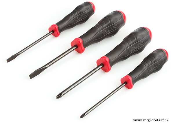
- 螺丝刀 - 大部分部件采用螺栓连接;
- 强力胶 - 部分零件使用强力胶粘合;
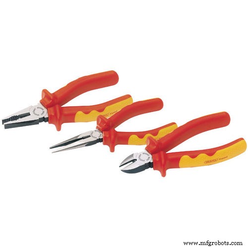
- 钳子和刀具
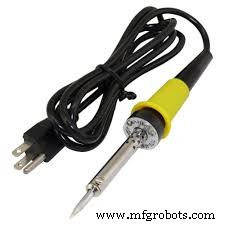
- 烙铁和电线
电子 :
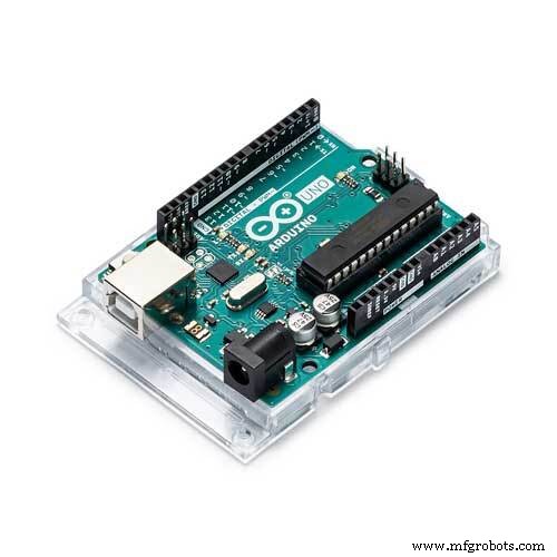
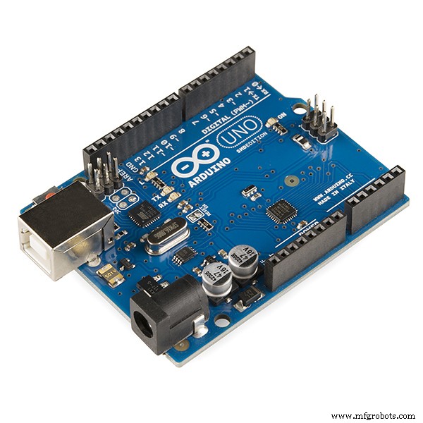
- Arduino Uno (link / link) - 用作机器人的主控制器。它向电机发送信号并与 WiFi 模块通信;
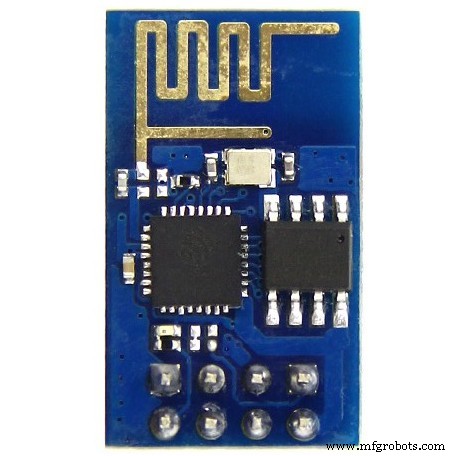
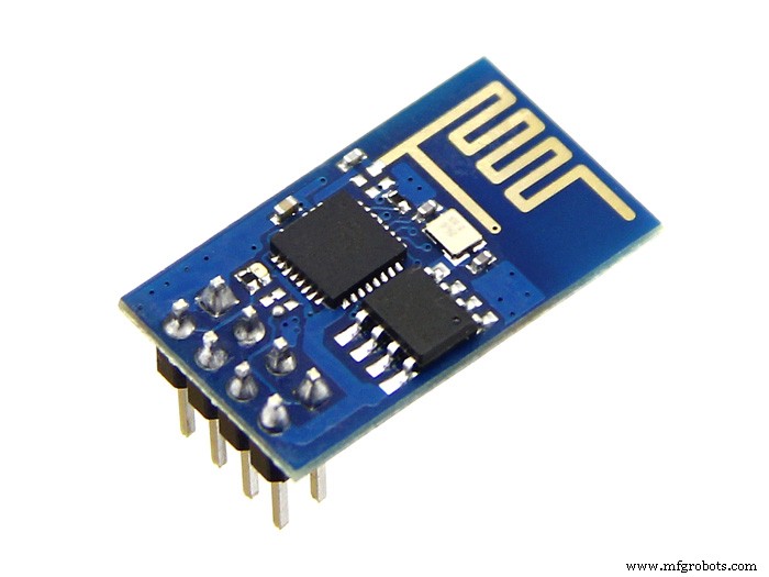
- ESP8266-01 (链接/链接)- 它用作“WiFi 调制解调器”。它从控制接口接收信号,由 Arduino Uno 执行;
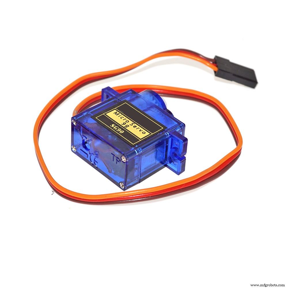
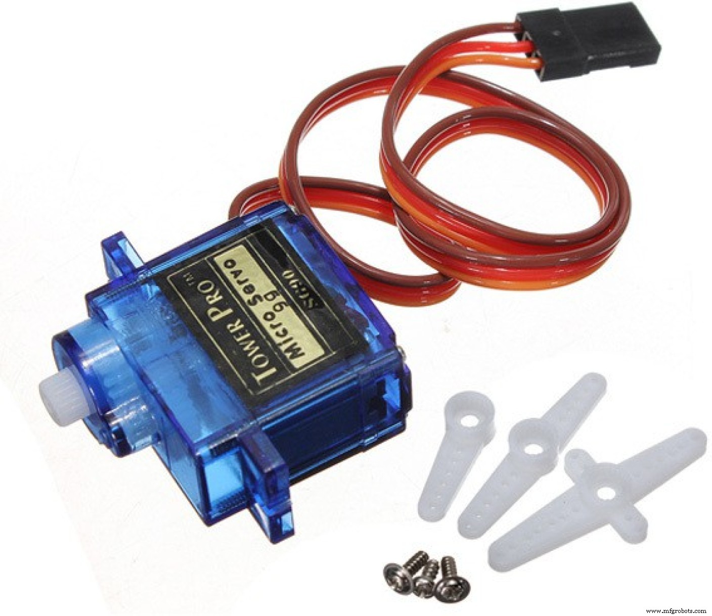
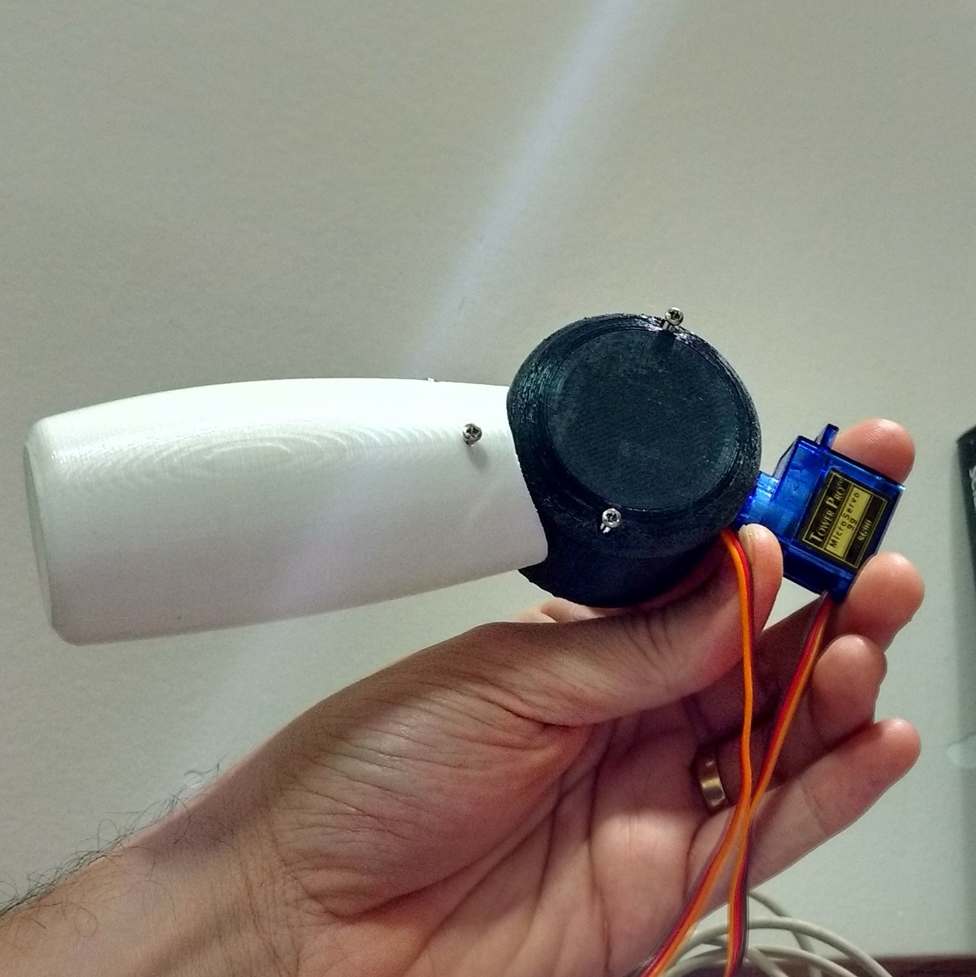
- SG90 伺服电机 (x6) (link / link) - 四个伺服器用于手臂,两个用于头部运动;
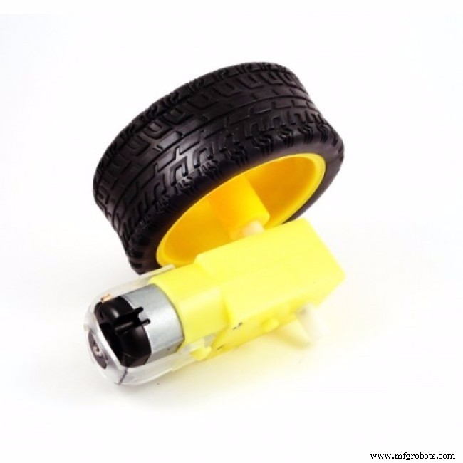
- 带减速和橡胶轮的直流电机 (x2) (link / link) - 它们允许机器人移动小距离;
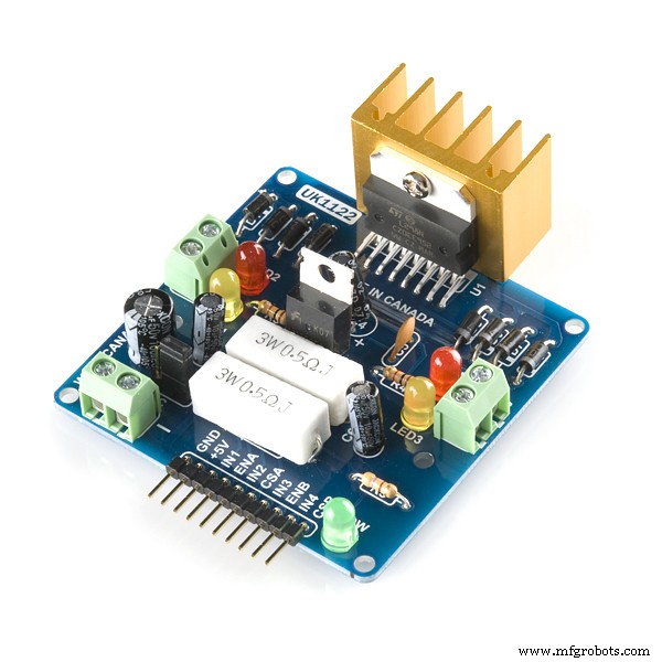
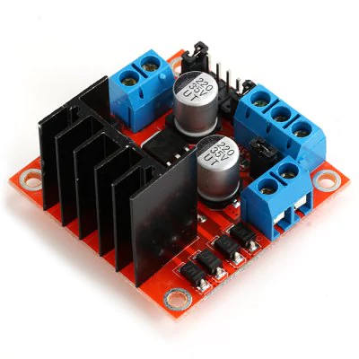
- L298N 双通道 H 桥 (x1) (link / link) - 它将 Arduino 数字输出转换为电机的电源电压;
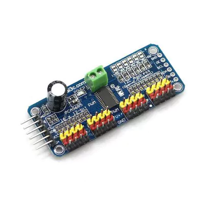
- 16 通道伺服控制器 (链接/链接)- 使用此板,只需使用两个 Arduino 输出即可控制多个伺服电机;
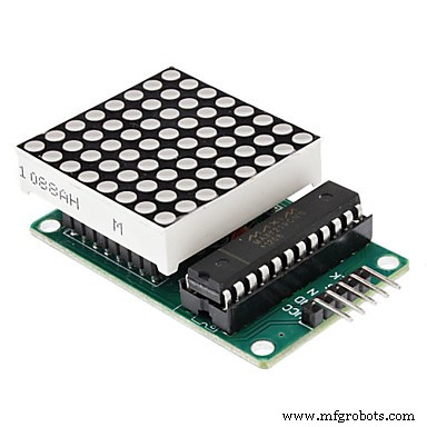
- MAX7219 8x8 LED 显示屏 (x4) (link / link) - 它们被用作机器人的脸;
- 微型 USB 数据线 - 用于上传代码;
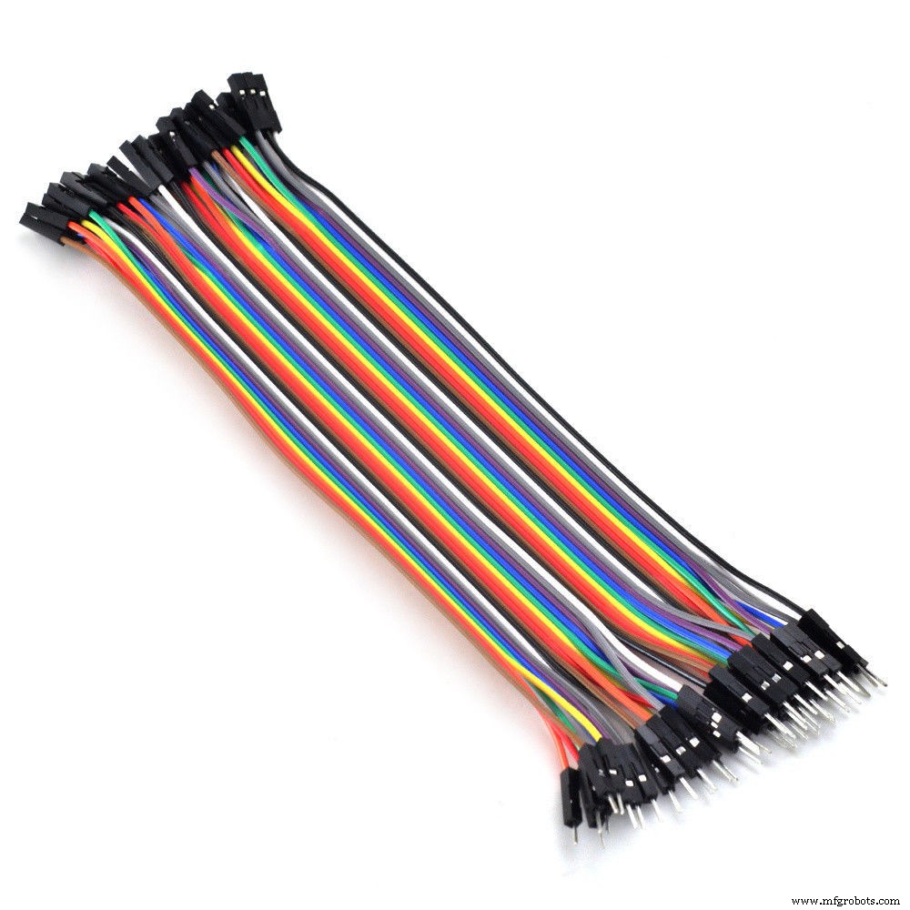
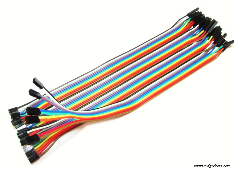
- 母-母跳线 (一些);
- 公母跳线 (一些);
- 智能手机 - 使用了摩托罗拉 4.3" Moto E 智能手机。其他类似尺寸的智能手机也可以使用;
- 18650 电池 (x2) (link) - 它们用于为 Arduino 和其他外围设备供电;
- 18650 电池座 (x1) (link / link) - 它们将电池固定到位;
- 1N4001 二极管 (x2)
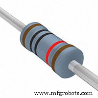
- 10 kohm 电阻器 (x3)
- 20mm 开/关开关 (x1)
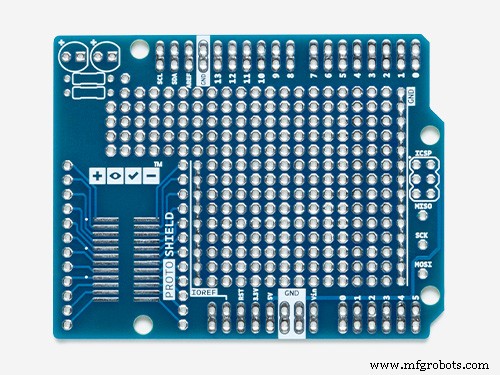
- 原盾 (链接) - 它有助于连接电路。
力学:
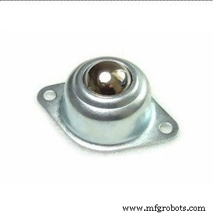
- 球轮 (x2)
- M2x6.0mm 螺栓 (+-70)
- M2x10mm 螺栓 (+-20)
- M2x1.5mm 螺母 (x10)
- M3x40mm 螺栓 (x4)
- M3x1.5mm 螺母 (x4)
上面的链接是建议您在哪里可以找到本教程中使用的项目并支持该项目的开发。随意在其他地方搜索它们并在您最喜欢的本地或在线商店购买。
您是否知道只需 349.99 美元即可购买 Creality3D CR10mini?在 Gearbest 使用优惠券代码 cr10mini3d 并获取它:http://bit.ly/2FZ5OXw
第 3 步:3D 打印

机器人结构完全是使用 Autodesk Fusion 360 通过 3D 打印制作的。为了能够在创客空间或制造实验室中生产机器人复制品,其中打印机的最长使用时间至关重要,机器人的设计被分成几部分每个打印时间少于三个小时。该组零件通过胶合或螺栓连接用于车身安装。
该模型由 36 个不同的部分组成。大部分是在没有支撑的情况下打印的,有 10% 的填充物。
- 头顶(右/左)
- 头部底部(右/左)
- 头部侧盖(右/左)
- 面背板
- 前面板
- 颈部轴 1
- 颈部轴 2
- 颈部轴 3
- 颈部中心
- 手臂(右/左)
- 肩膀(右/左)
- 肩杯(右/左)
- 肩帽(右/左)
- 臂轴(右/左)
- 胸围(右/左)
- 胸部(右/左/前)
- 轮子(右/左)
- 基础
- 手机支架
- 后退(右/左)
- 旋钮(右/左)
- 储物柜(右/左)
机器人的安装步骤如下所述。
您可以在以下网站下载所有 stl 文件:
- https://www.thingiverse.com/thing:2765192
- https://pinshape.com/items/42221-3d-printed-joy-robot-robo-da-alegria
- https://www.youmagine.com/designs/joy-robot-robo-da-alegria
- https://cults3d.com/en/3d-model/gadget/joy-robot-robo-da-alegria
这是一个实验原型。某些部分需要一些改进(用于项目的后续更新)。有一些已知问题:
- 部分舵机接线与肩部干扰;
- 头部和胸部之间的摩擦;
- 车轮与结构之间的摩擦;
- 有些螺丝孔太紧,需要用钻头或小刀扩大。
如果您没有 3D 打印机,您可以执行以下操作:
- 请朋友为您打印;
- 在附近找一个黑客/创客空间。该模型分为几个部分,因此每个部分的打印时间不到四个小时。一些黑客/创客空间只会向您收取所用材料的费用;
- 购买自己的 3D 打印机。您只需 165.99 美元即可找到 Anet A8。在 Gearbest 获取您的:http://bit.ly/2kqVOdO
- 有兴趣购买 DIY 套件吗?如果有足够多的人感兴趣,我可能会在 Tindie.com 上提供 DIY 套件。如果你想要一个,给我发消息。
第 4 步:电路概述
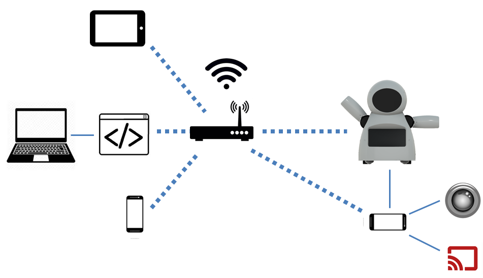
该机器人的核心是使用 Arduino Uno 进行控制。 Arduino 连接了一个 ESP8266-01 模块,用于通过 Wi-Fi 网络远程控制机器人。
一个 16 通道伺服控制器使用 I2C 通信连接到 Arduino 并控制 6 个伺服电机(两个用于颈部,每个手臂两个)。五个 8x8 LED 矩阵阵列由 Arduino 供电和控制。四个Arduino的数字输出用于控制两个直流电机,使用一个h桥。
电路使用两个 USB 移动电源供电:一个用于电机,另一个用于 Arduino。我尝试使用单电源组为整个机器人供电。但是 ESP8266 曾经在直流电机打开/关闭时由于尖峰而失去连接。
机器人的胸部有一部智能手机。它用于向/从位于普通计算机上的控制接口广播视频和音频。它还可以向ESP6288发送命令,从而控制机器人本身。
人们可能会注意到这里使用的组件可能没有针对其目的进行优化。例如,可以使用 NodeMCU 代替 Arduino + ESP8266 组合。带有摄像头的 Rapsberry Pi 将取代智能手机并控制电机。甚至可以将 Android 智能手机用作机器人的“大脑”。确实如此... 选择 Arduino Uno 是因为它对每个人来说都非常易于访问且易于使用。到我们开始这个项目时,ESP 和 Raspberry Pi 板在我们居住的地方仍然相对昂贵......曾经我们想建造廉价的机器人,Arduino 板是当时最好的选择。
机器人%2Bmk0%2B-%2Brev8_Esquem_C3_A1tico.pdf 机器人%2Bmk0%2B-%2Brev8_bb.pdf
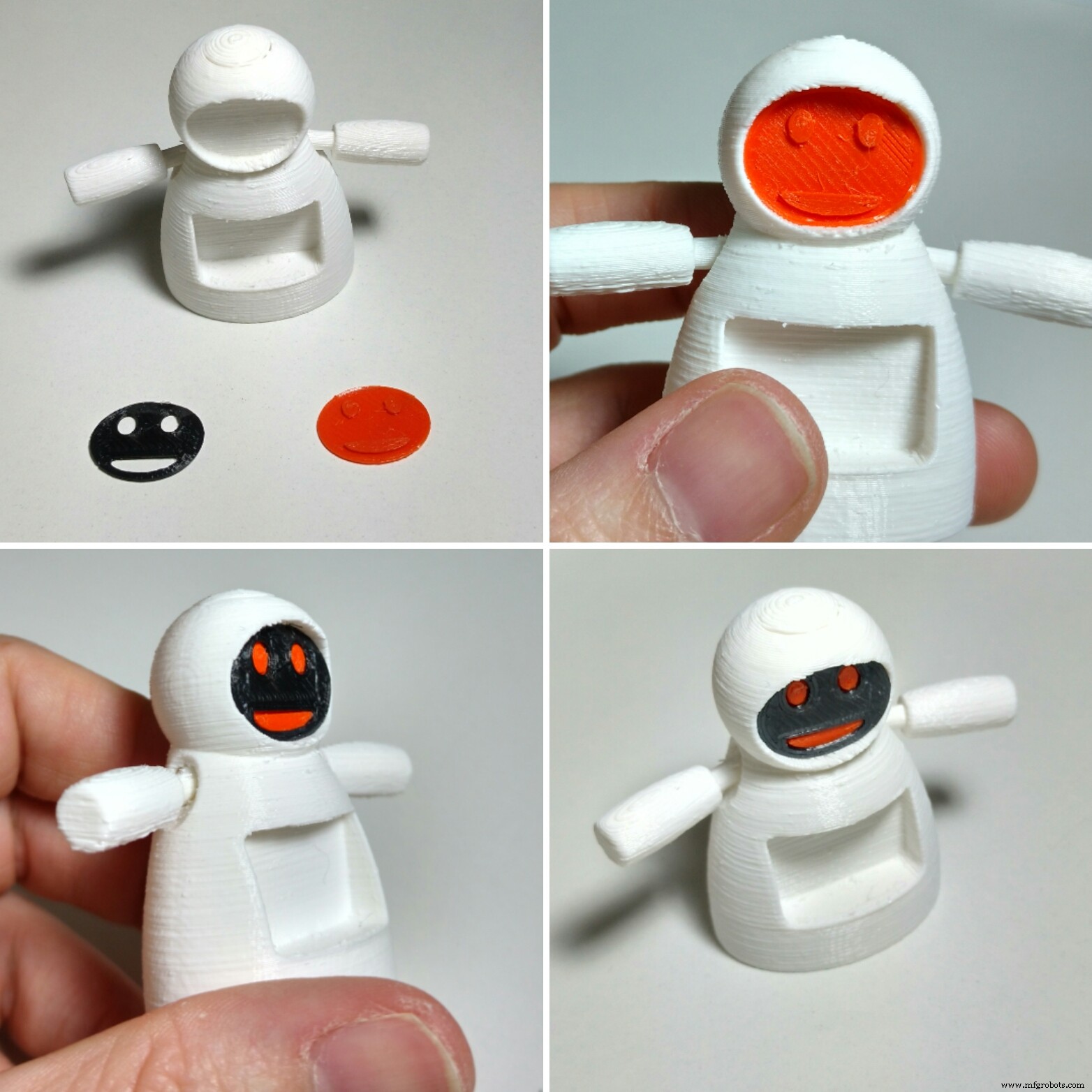
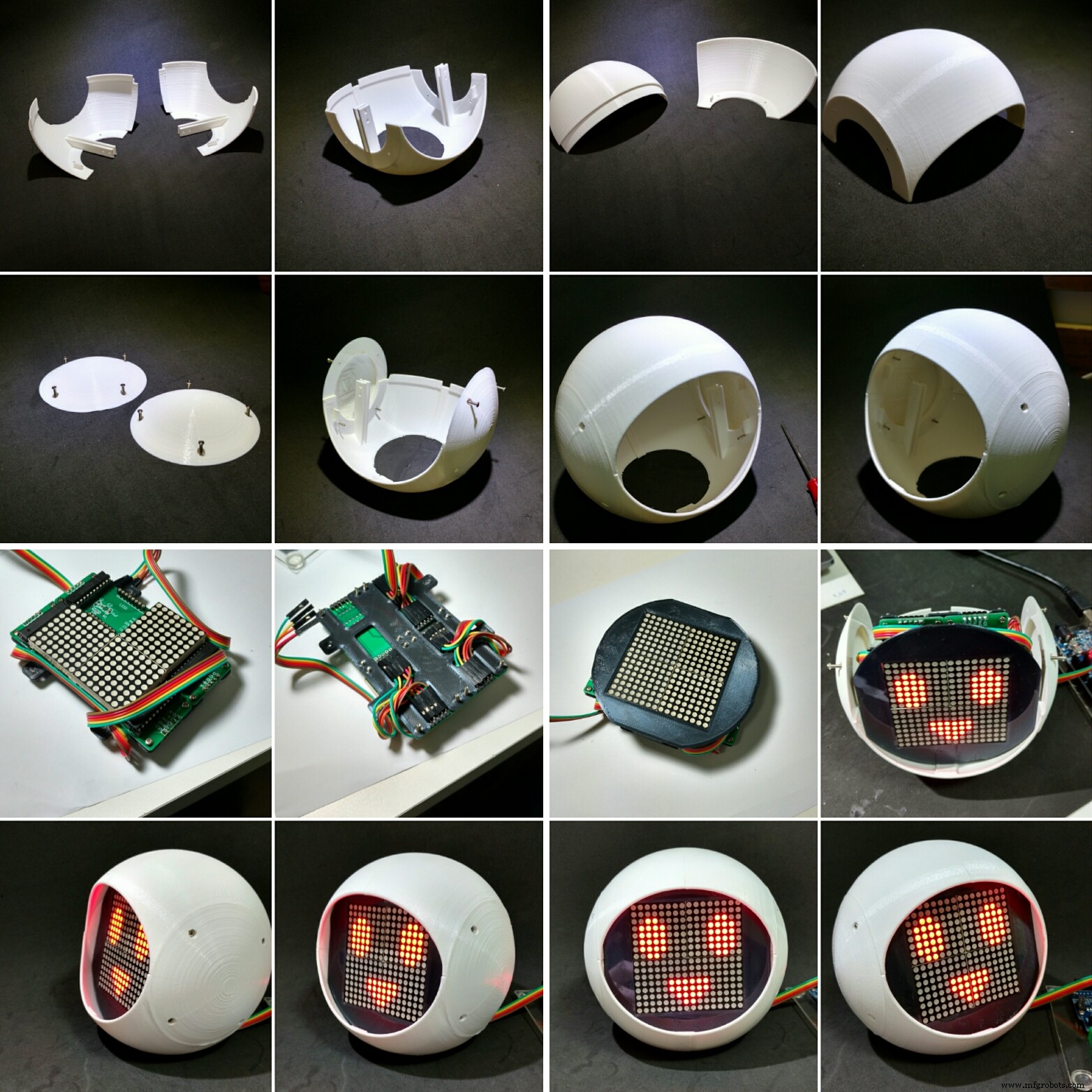
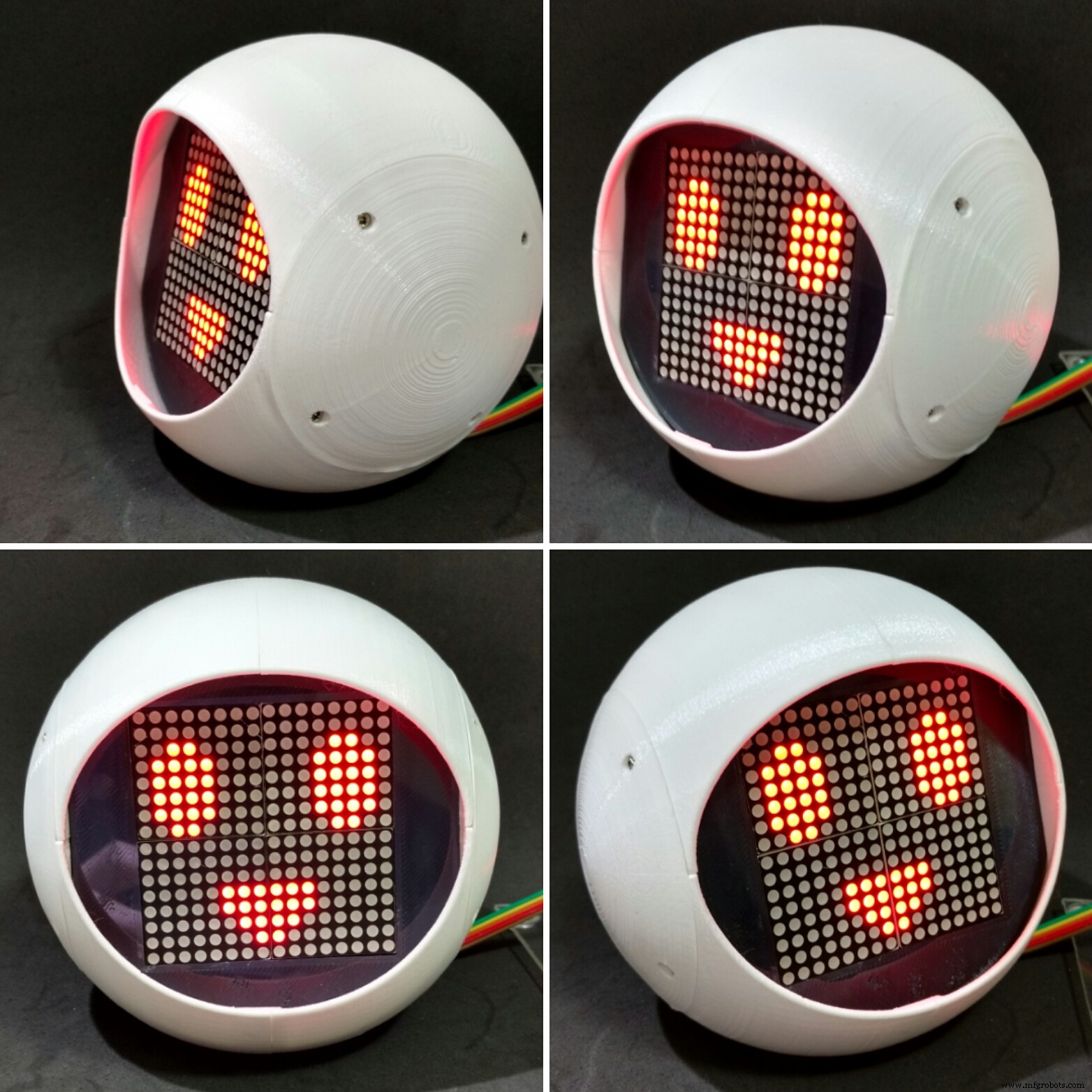
第 5 步:组装面部
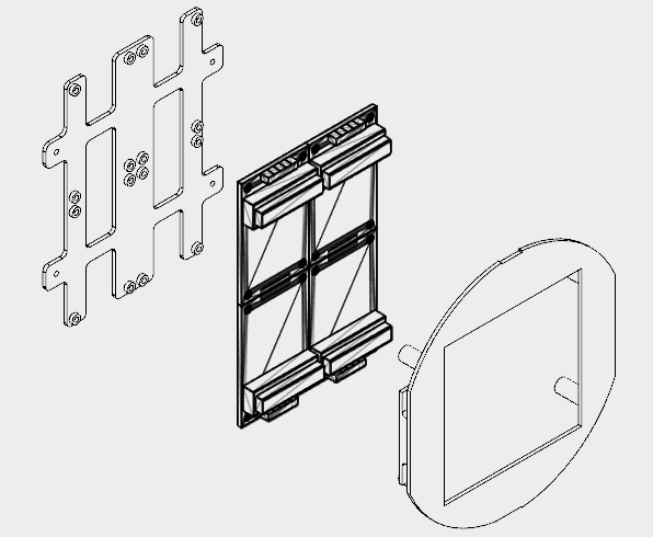

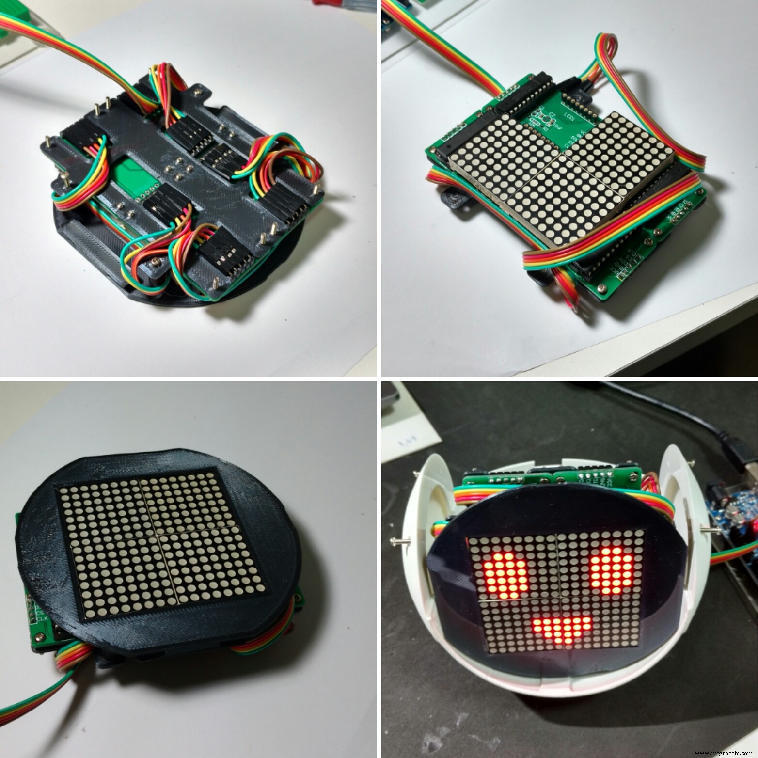
机器人面部采用四个8x8 LED矩阵。
该结构分为两部分(正面背板和正面面板),使用黑色 PLA 3D 打印。我花了大约 2.5 小时来 3D 打印它们,填充 10%,没有支撑。
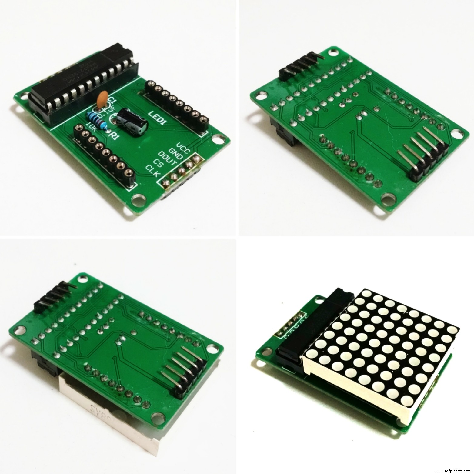
由于空间限制,必须将 LED 矩阵的连接器拆焊并更改其位置,如下所述:
- 移除LED矩阵;
- 拆焊输入和输出连接器;
- 在电路板的另一侧重新焊接,针脚指向电路板的中心。
您可以在图像中看到最终结果。
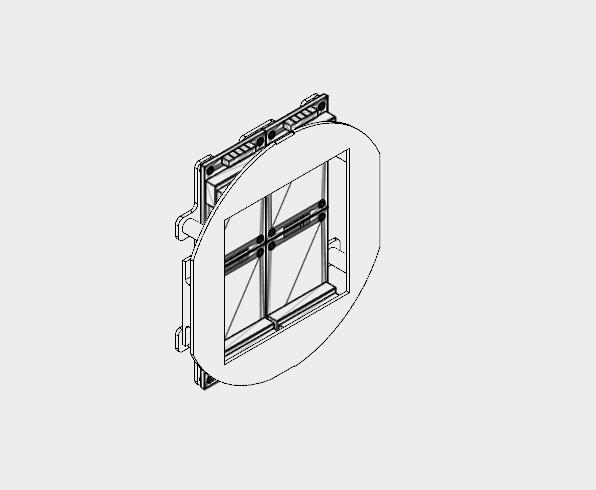
然后使用 16 个 M2x6mm 螺栓将四个 LED 矩阵连接到背板上。引脚按照原理图连接。
第一个矩阵使用 5 线公母跳线连接。公端后来连接到 Arduino 引脚。母端连接在矩阵输入引脚上。每个矩阵的输出通过母-母跳线连接到下一个矩阵的输入。
矩阵连接后,使用四个 M2 螺栓安装前板。将跳线缠绕在前后面板上,以免电线松动。
面部模块稍后安装在机器人的头部内部,将在接下来的步骤中解释。
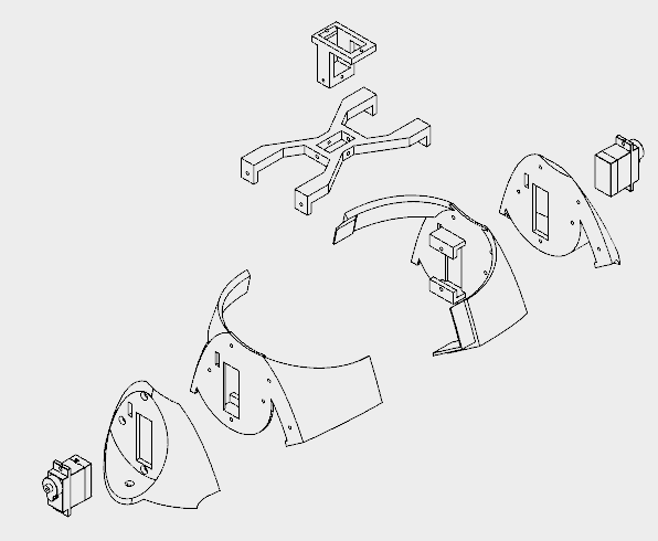
第 6 步:安装头部
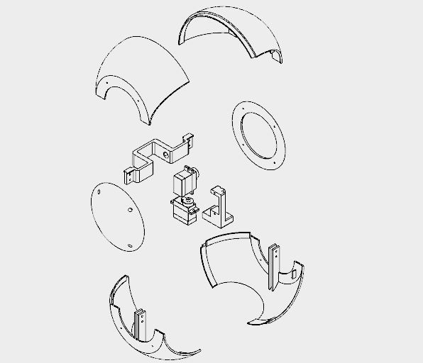
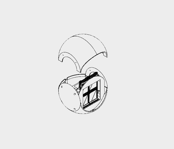
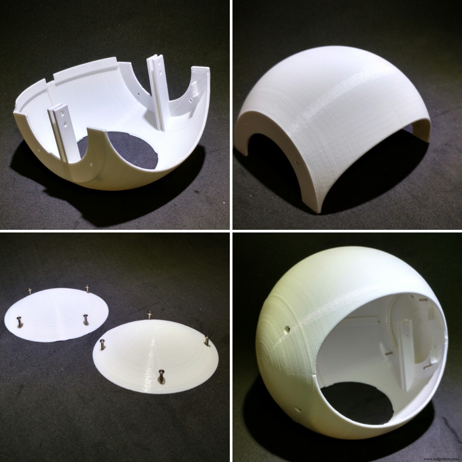
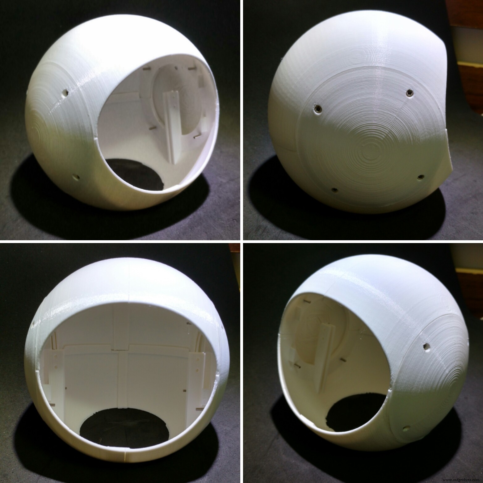

机器人的头部被分成八个 3d 打印部件,所有部件均采用白色 PLA 打印,分辨率为 0.2mm,填充率为 10%,无支撑:
- 头顶(左右)
- 头部底部(左右)
- 头帽(左右)
- 颈部轴 1
- 颈部轴 2
打印直径130毫米的结构花了我将近18个小时。
头部的顶部和底部分为两部分。它们用强力胶粘在一起。涂上胶水,让它休息几个小时。
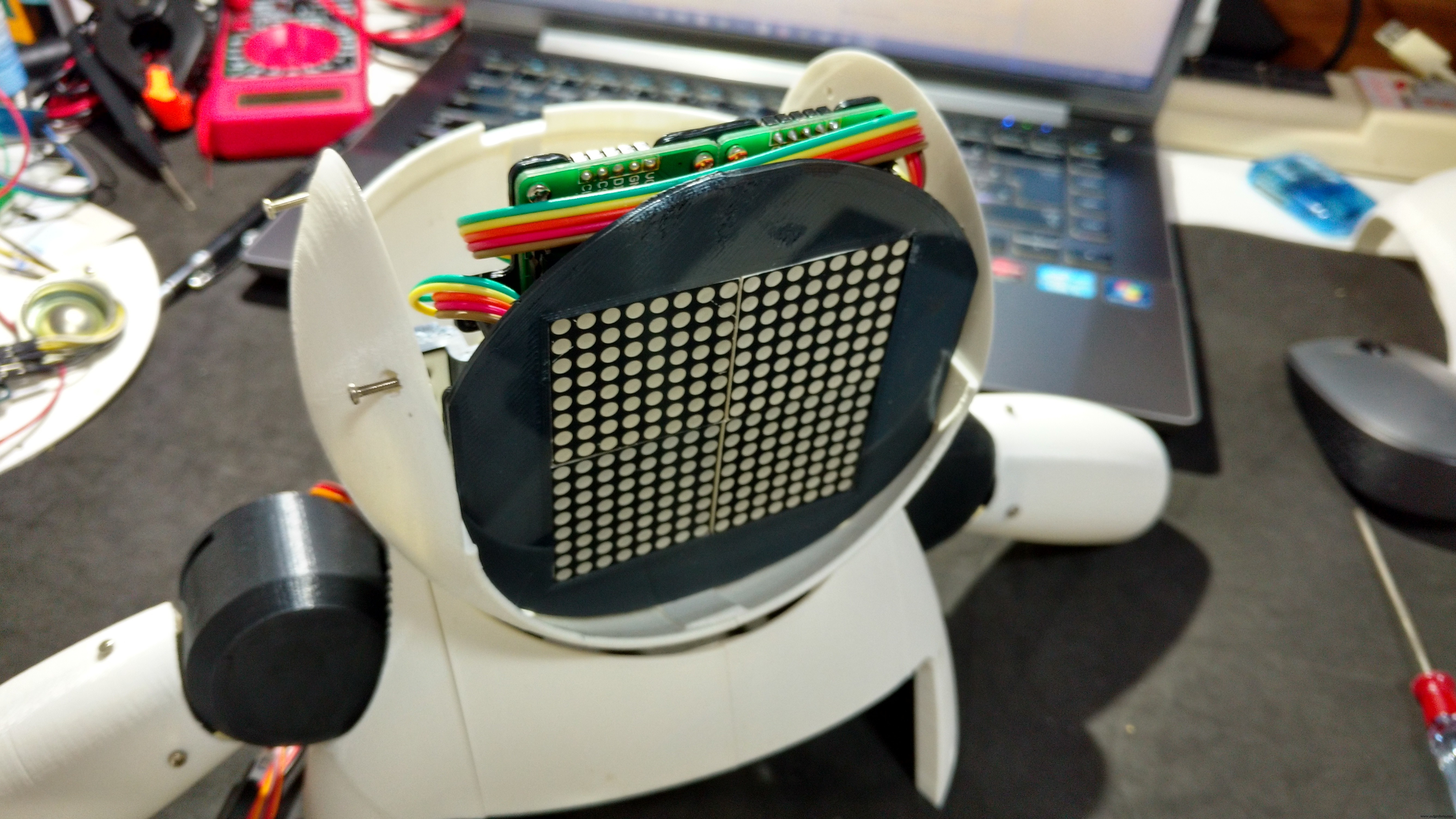
然后使用连接到头部顶部和底部两侧的螺栓安装侧盖。通过这种方式,可以通过卸下连接到头部顶部的螺钉来拆卸头部进行维修。在合上头部之前,组装机器人的脸(在上一步中描述)和胸围(在下一步中描述)。
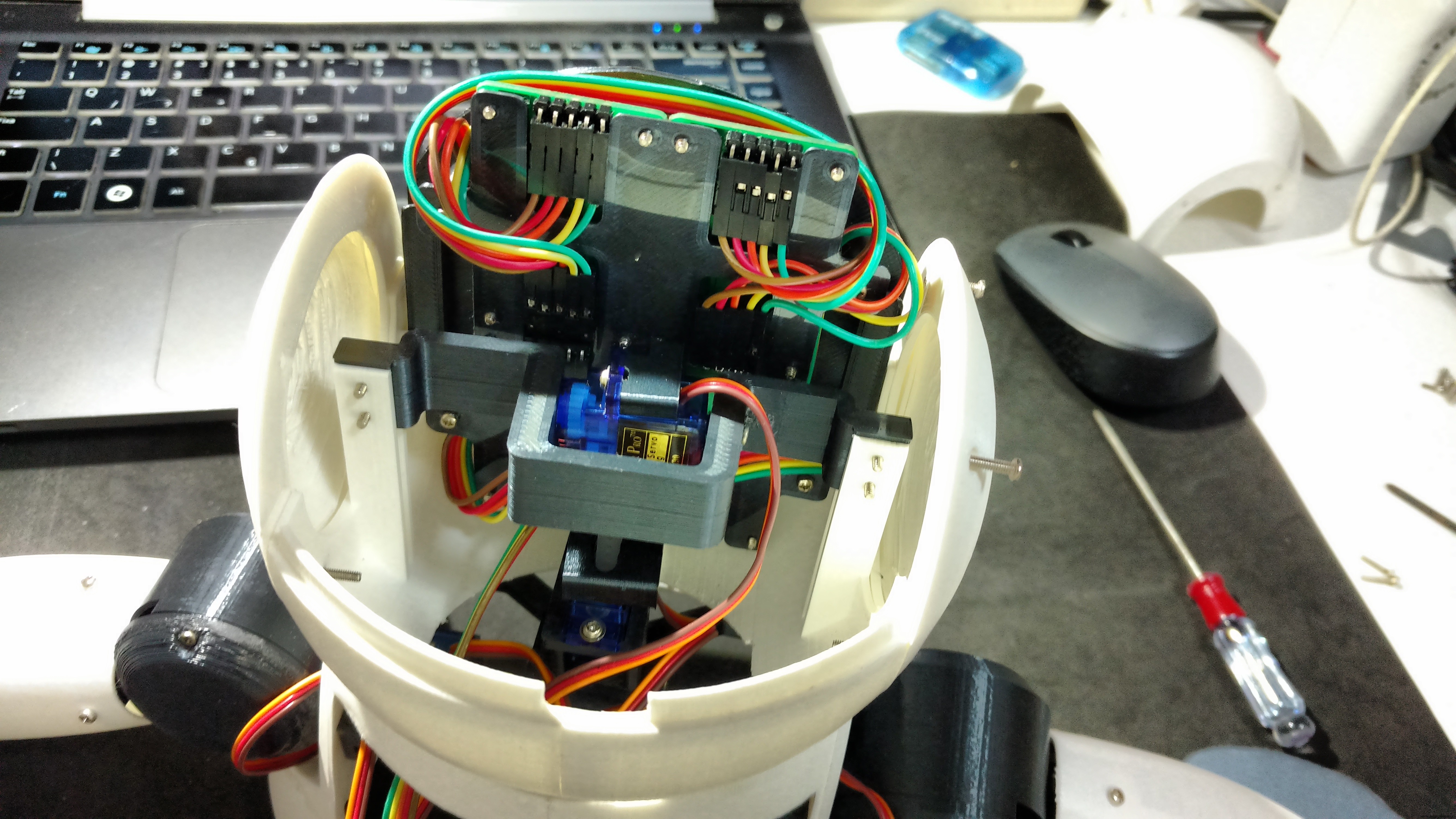
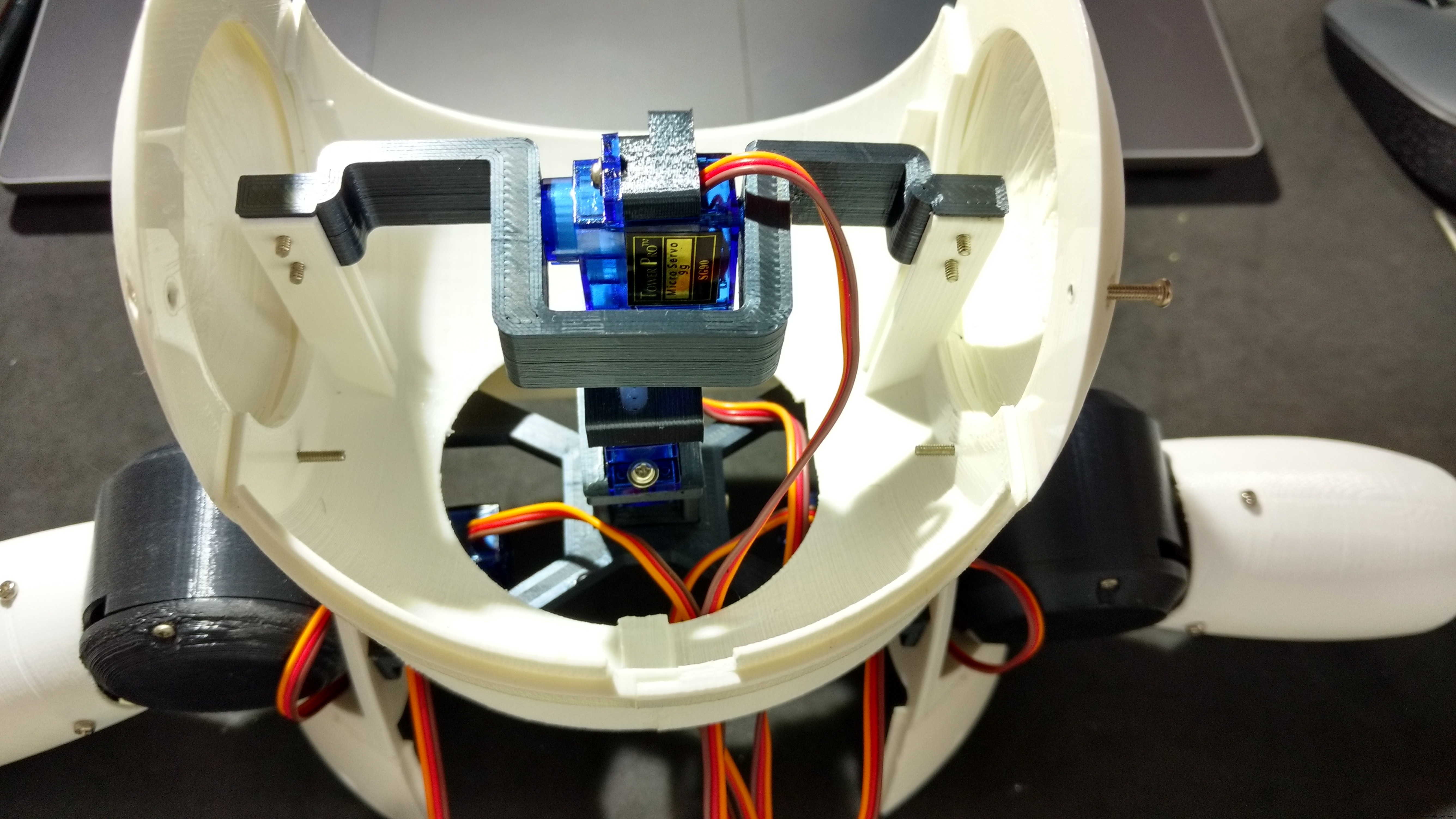
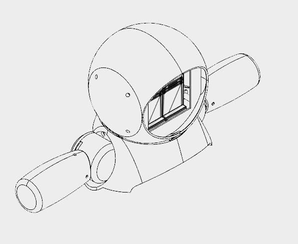
伺服电机 #5 连接到颈部轴 1。我将伺服电机定位在轴的中间,然后连接喇叭并使用螺钉锁定其位置。我使用两个 M2x6mm 螺栓将 Neck 轴 2 安装在该伺服电机上。伺服电机 #6 以同样的方式连接到 Neck 轴 2。
颈部轴 2 后来连接到颈部中心,如下一步所示。
人脸模块安装在头部内部。
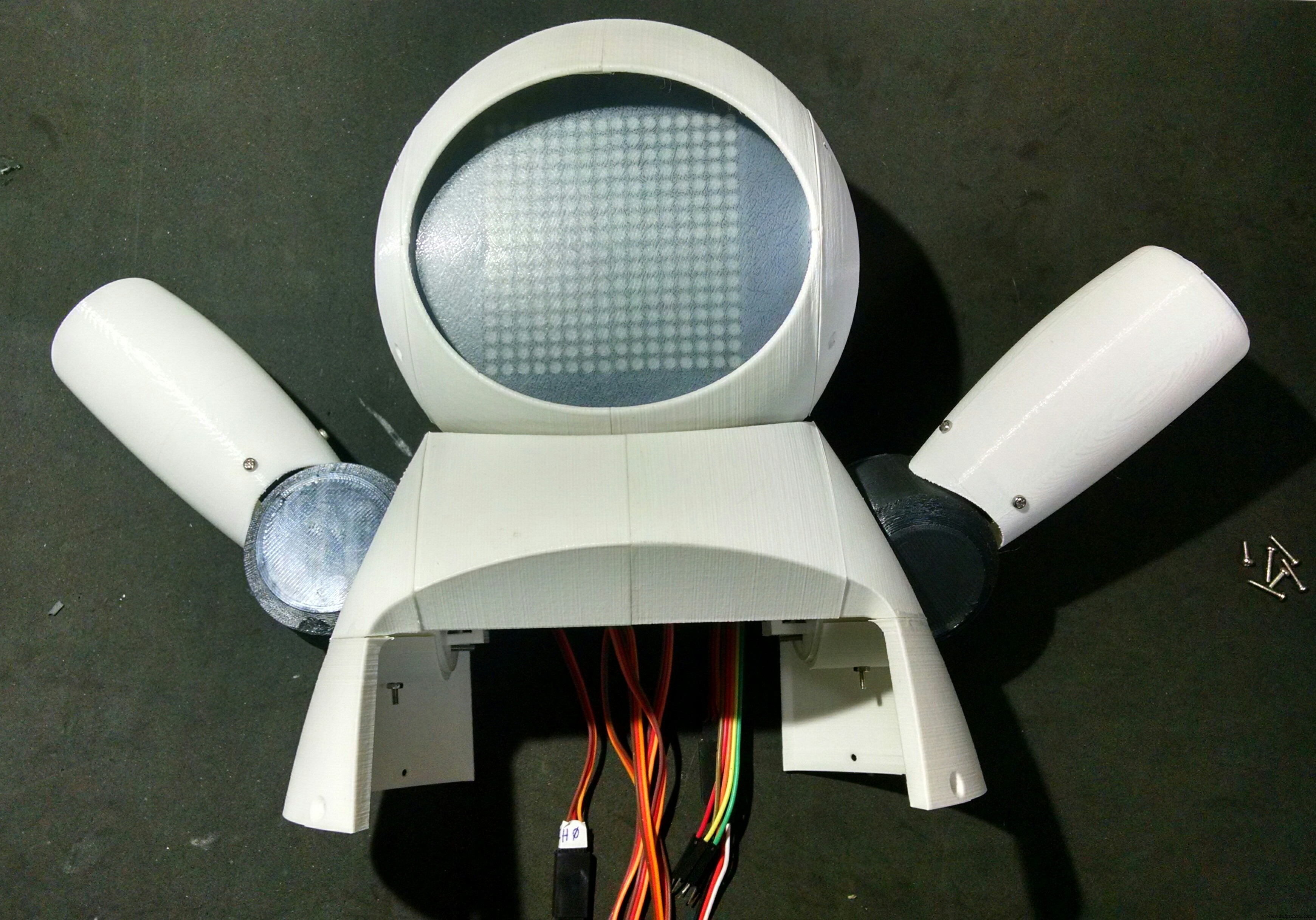
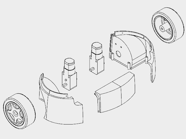
第 7 步:组装 Burst 和肩部
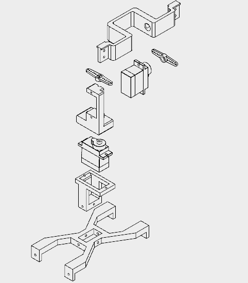
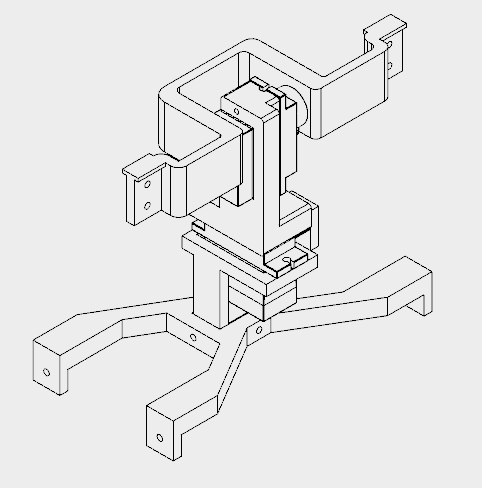
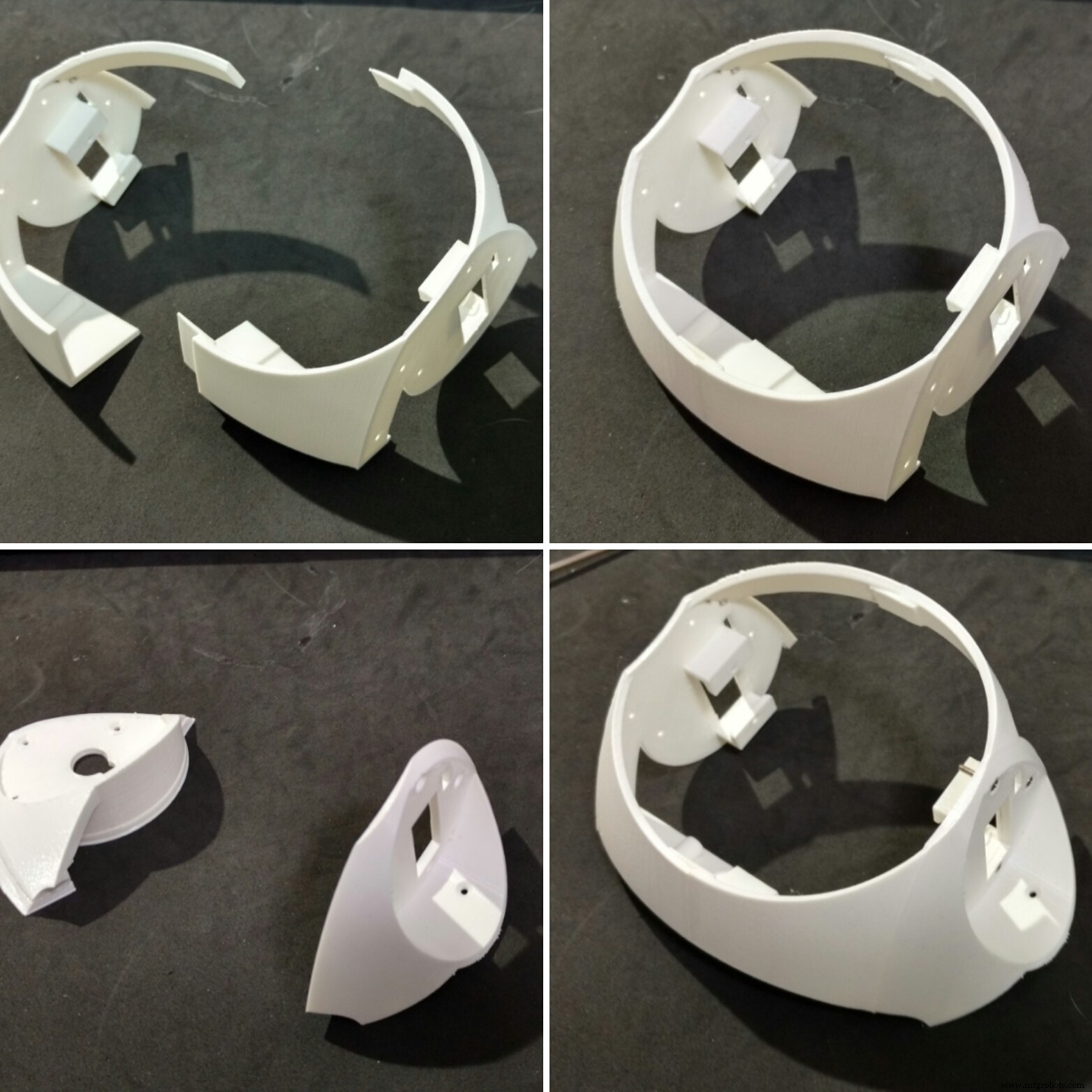
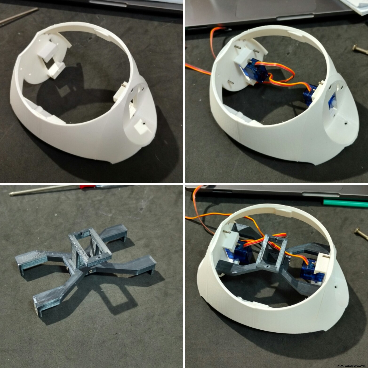

胸围和肩膀花了我大约 12 小时才打印出来。
本节由五个不同的部分组成:
- 胸围(右/左)
- 肩膀(右/左)
- 颈部中心
- 颈部轴 3
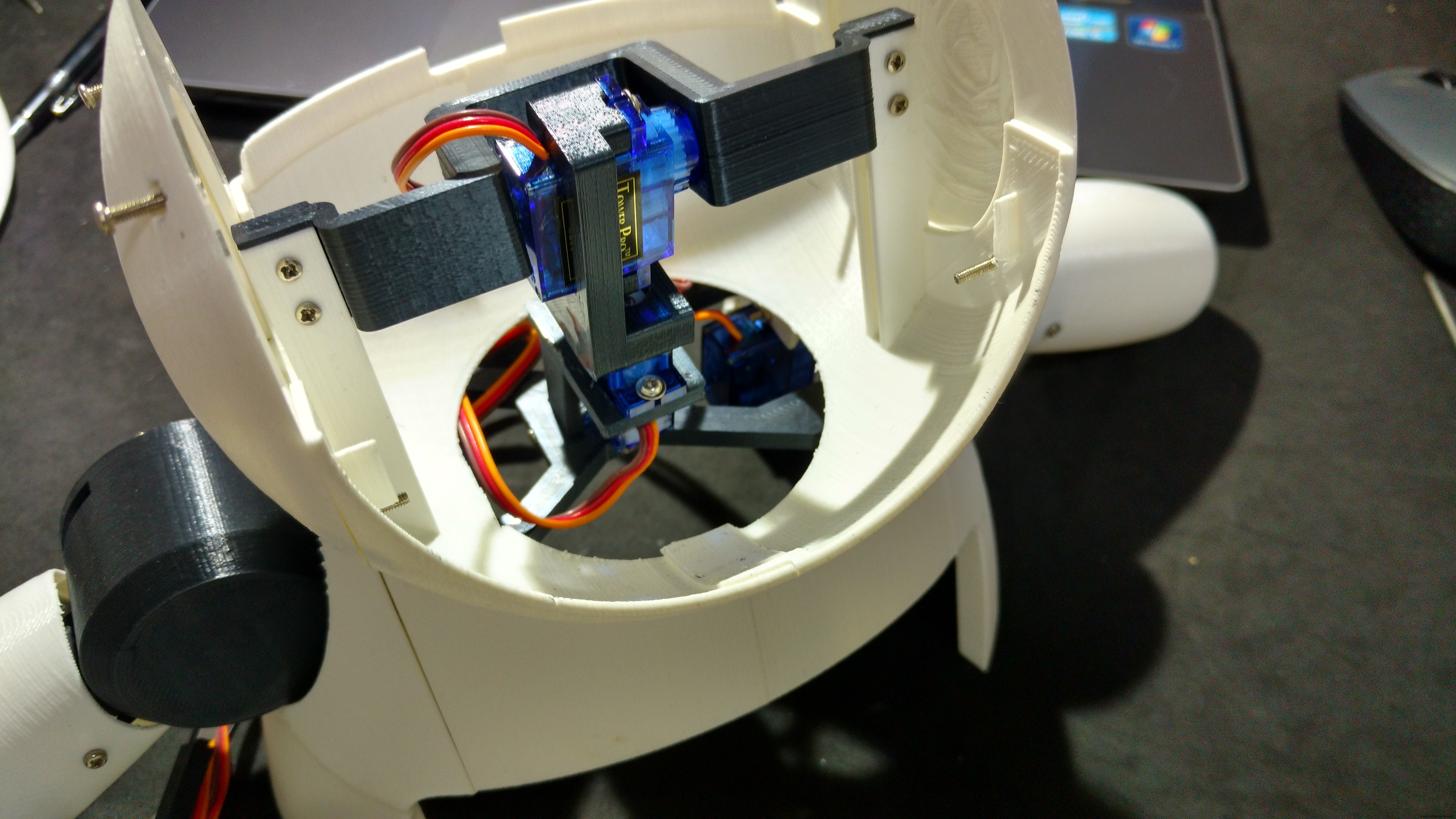
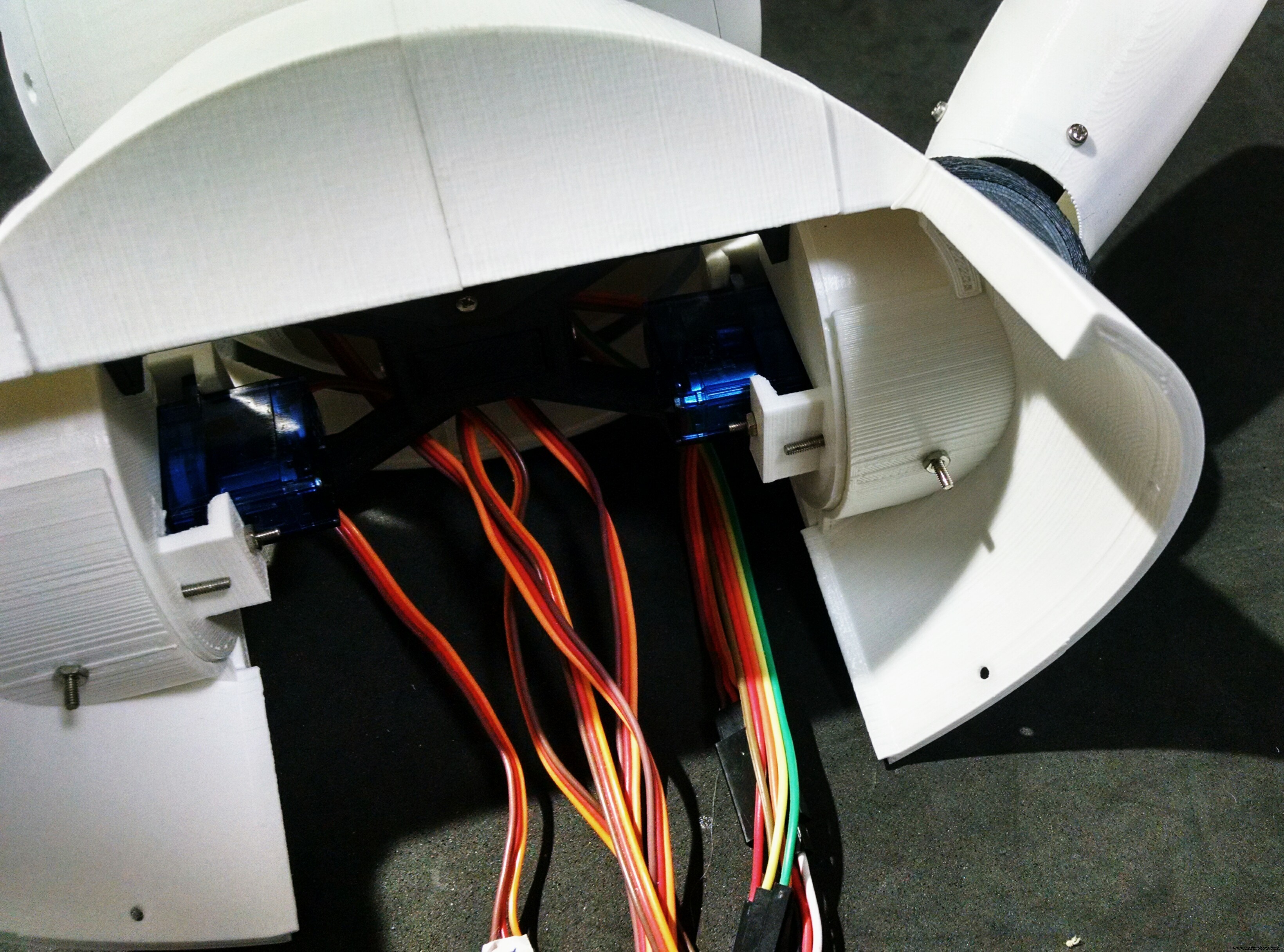
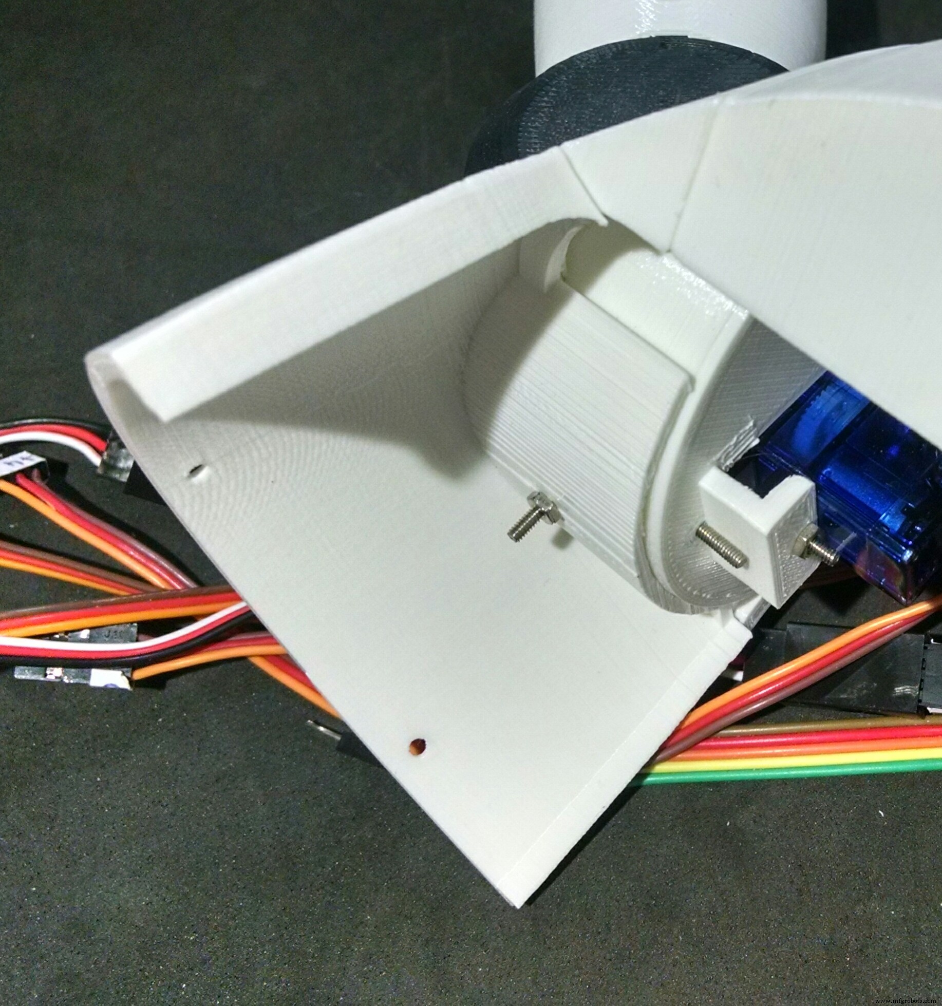
胸围部分使用强力胶粘合。肩部使用 M2x10mm 螺栓固定在两侧,伺服电机(伺服电机 #2 和 #4)安装在每一侧。它们穿过每个肩部的矩形孔(电线实际上很难穿过),并使用 M2x10mm 螺栓和螺母连接。
中心颈部有一个矩形孔,颈部轴 3 部分插入其中。四个 M2x6mm 螺栓用于连接这两个部分。之后,中央的脖子连接到肩膀上。它使用与用于将肩部安装在胸围上的相同螺栓。四个M2x1.5mm螺母用于锁定其位置。
伺服电机 #6 使用两个螺钉连接到颈部轴 3。然后我将Neck轴3安装在Neck中心矩形孔内,并使用四个M2x6mm螺栓锁定其位置。
第 8 步:组装手臂
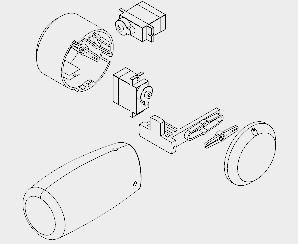

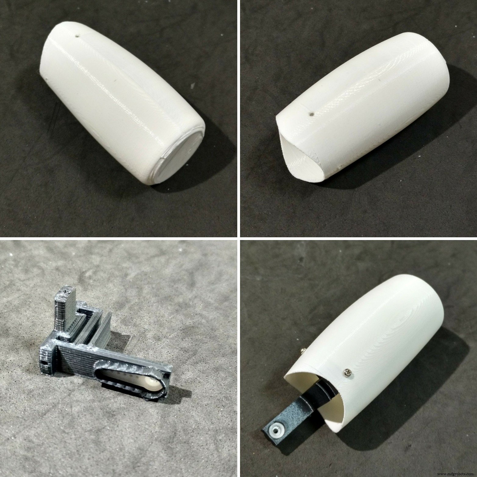
我花了大约 5 个小时来打印每条手臂。
每个手臂由四块组成:
- 肩杯
- 肩帽
- 臂轴
- 手臂
臂轴使用三个 M2x6mm 螺栓集中安装在臂本身上。轴的另一端装有伺服喇叭。
使用一些螺钉将伺服电机(#1 和 #3)安装在肩杯内,然后安装它的角(连接到臂轴的那个)。杯子上有一个孔用于安装其他喇叭,它连接到已经安装在肩部的舵机(#2 和 #4),如上一步所示。
杯子上(和肩部)还有一个孔,用于穿过伺服系统的电缆。之后,安装盖子以关闭机器人的肩部,用两个 M2x6mm 螺栓。
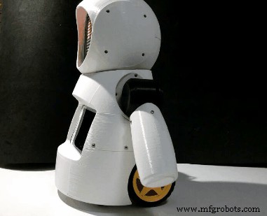
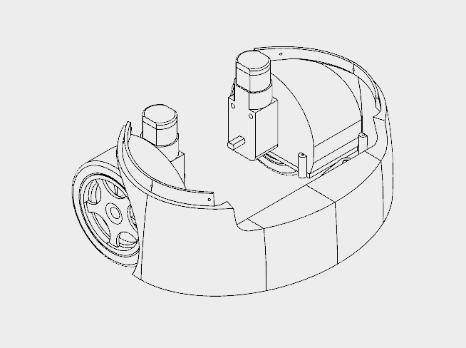
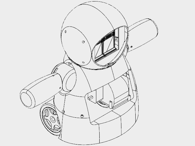
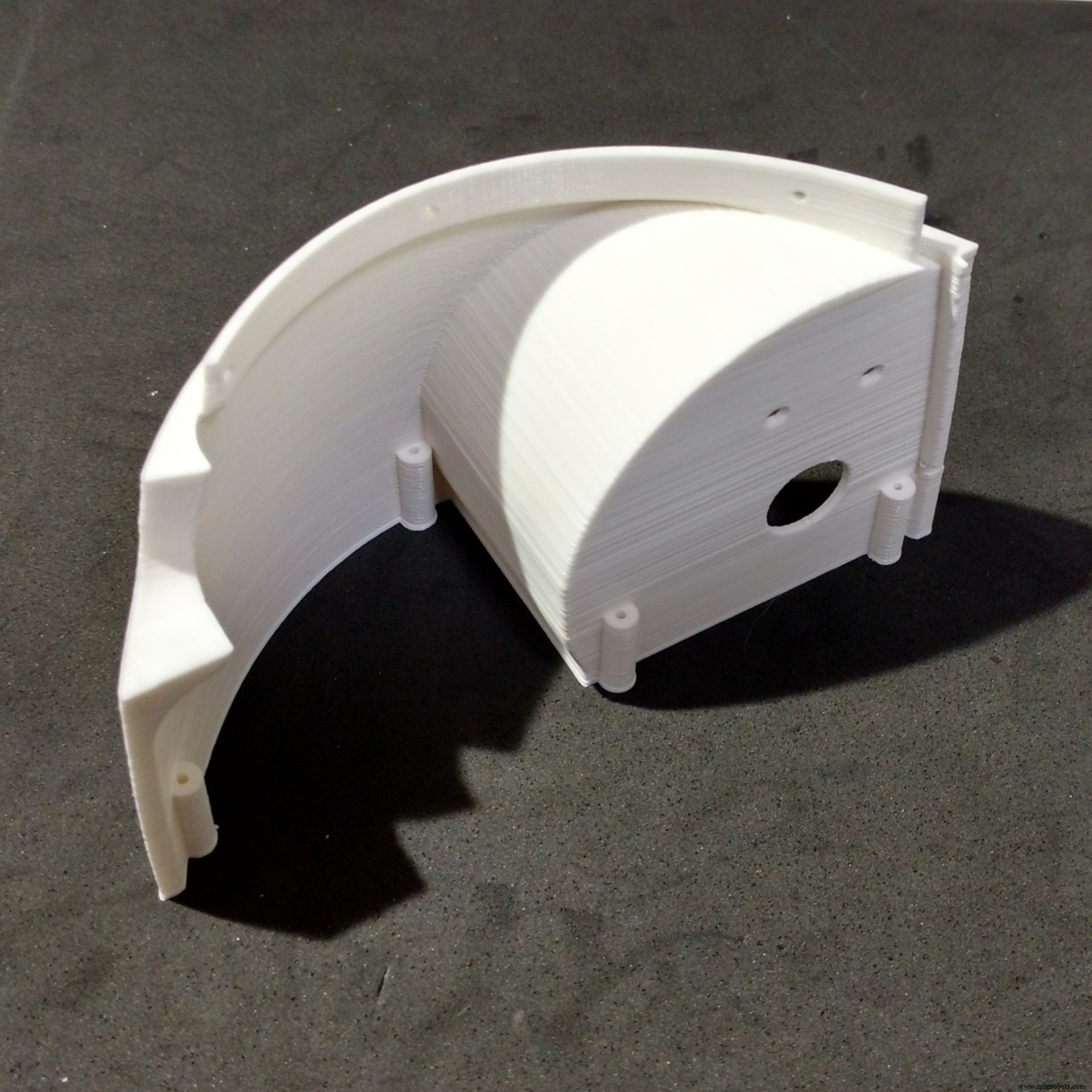
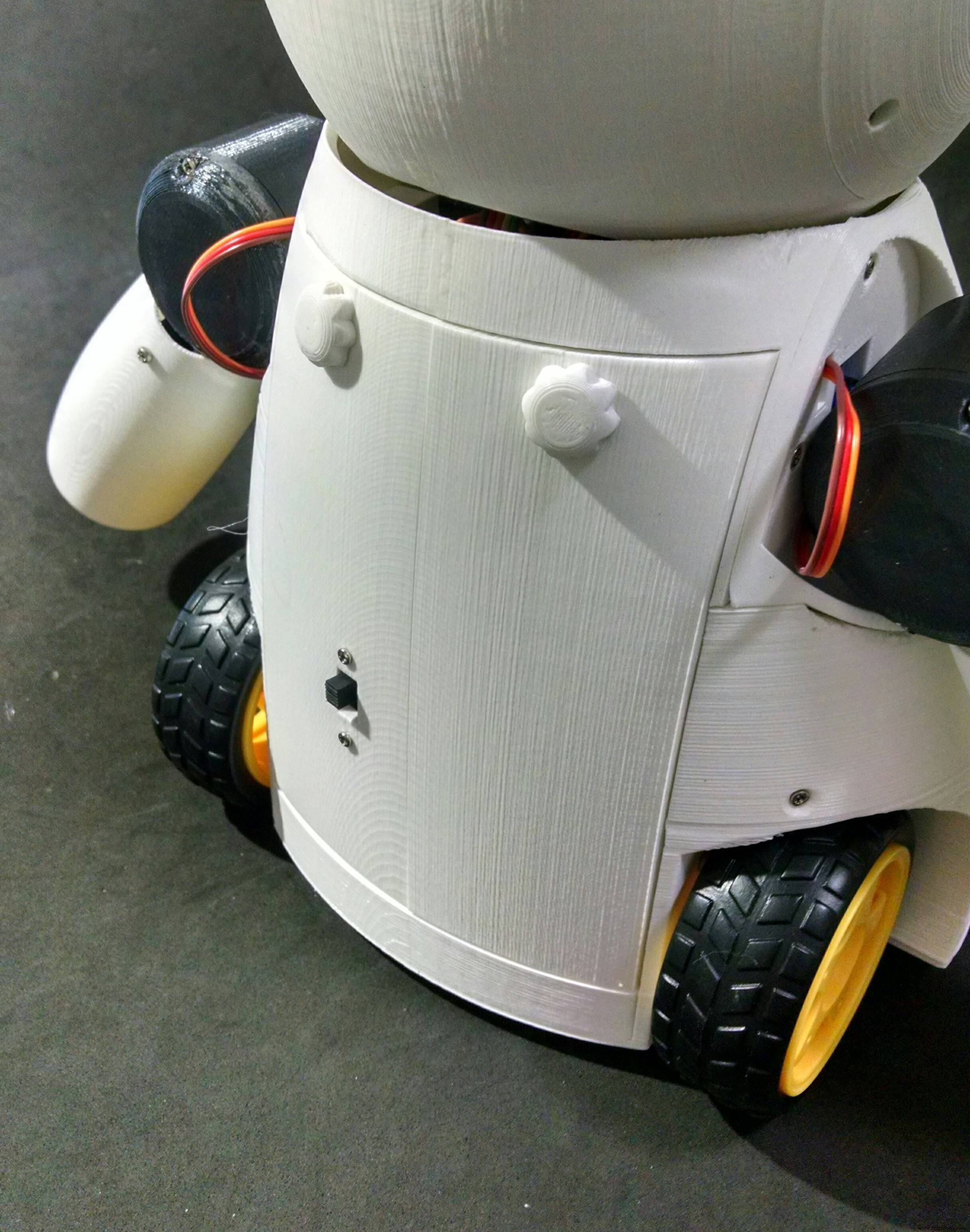
第 9 步:安装胸部
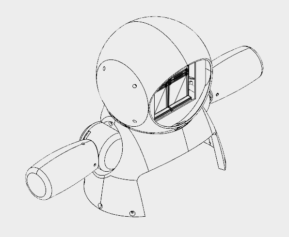
The chest is the part that links the bust to the bottom (wheels and base) of the robot. It's made of only two parts (right and left parts. I printed them in 4 hours.
The shoulders of the robot fits on upper part of the chest. There is a hole for a bolt that helps the alignment and fixation of thos parts. Although it's recomended to glue those two parts.
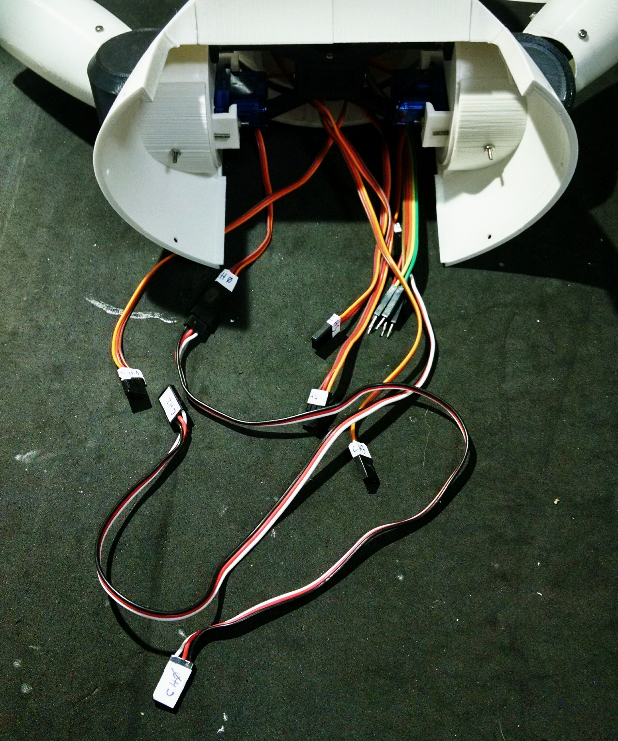
The bottom of this parts have six holes, which are used for the connection to the wheels, as it will be shown later.
At this point I labelled the servomotors with some stickers, in order to make the connection of the circuits easier.
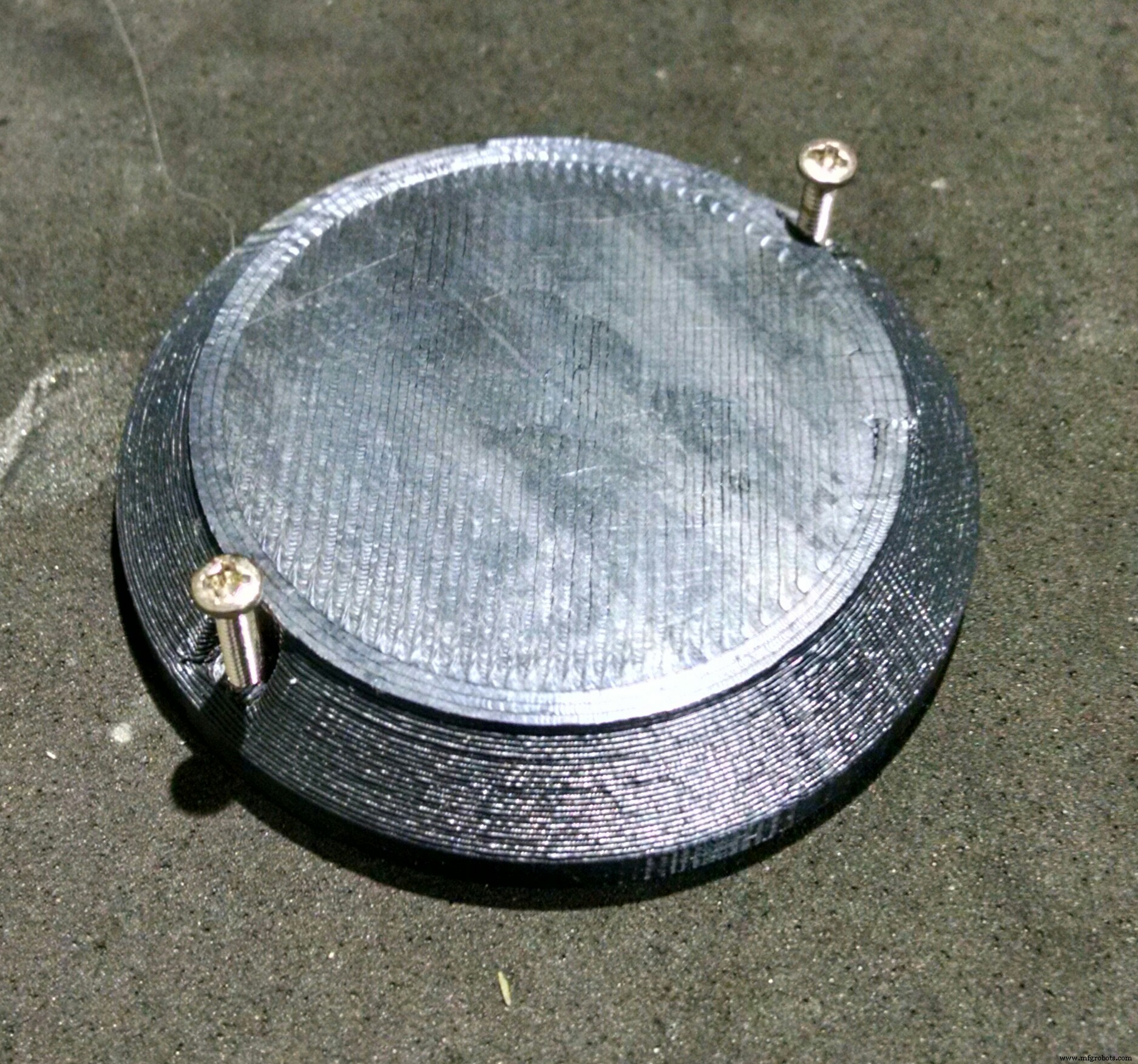
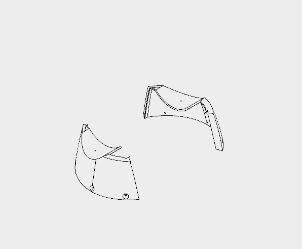
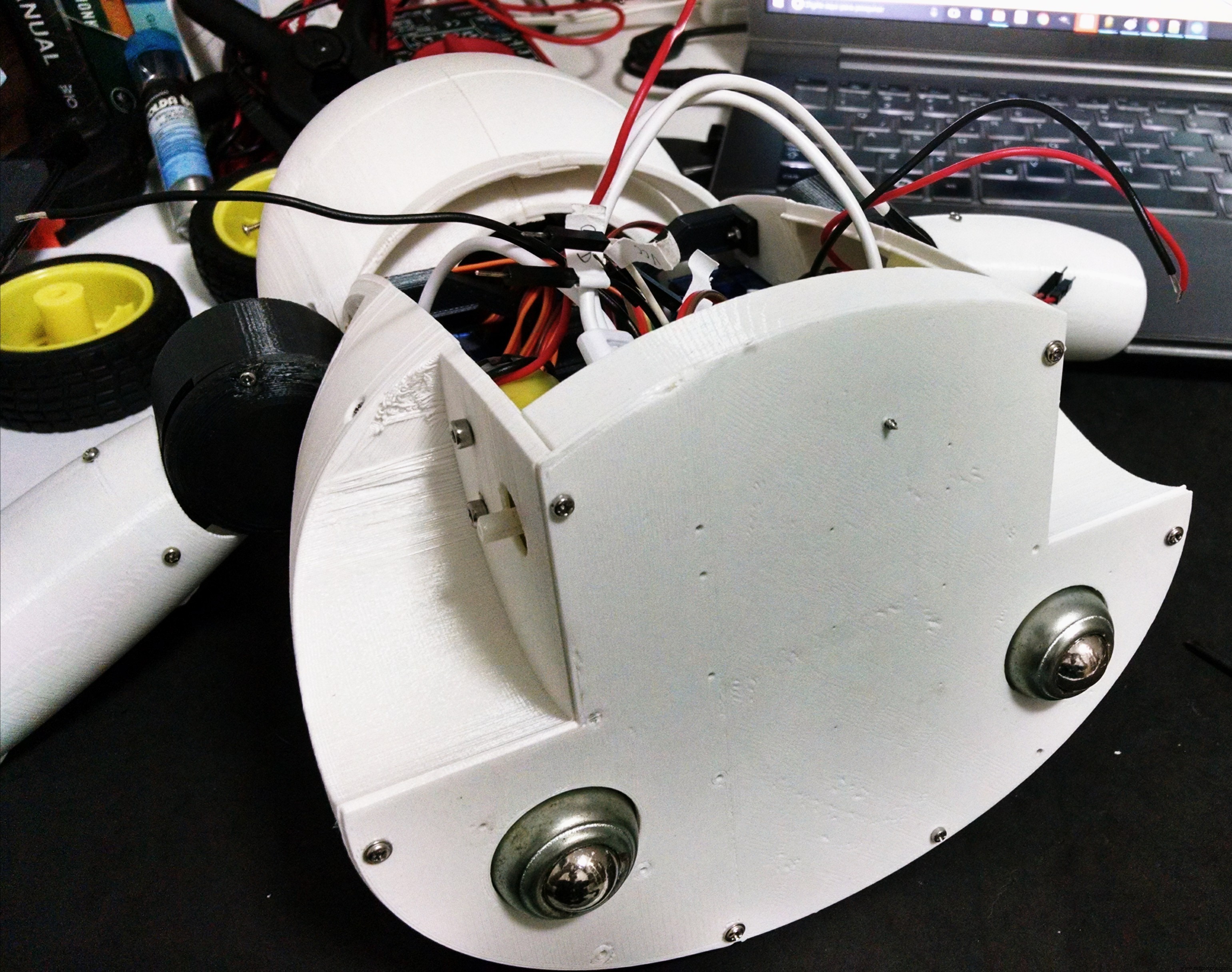
Step 10:Assembling the Wheels
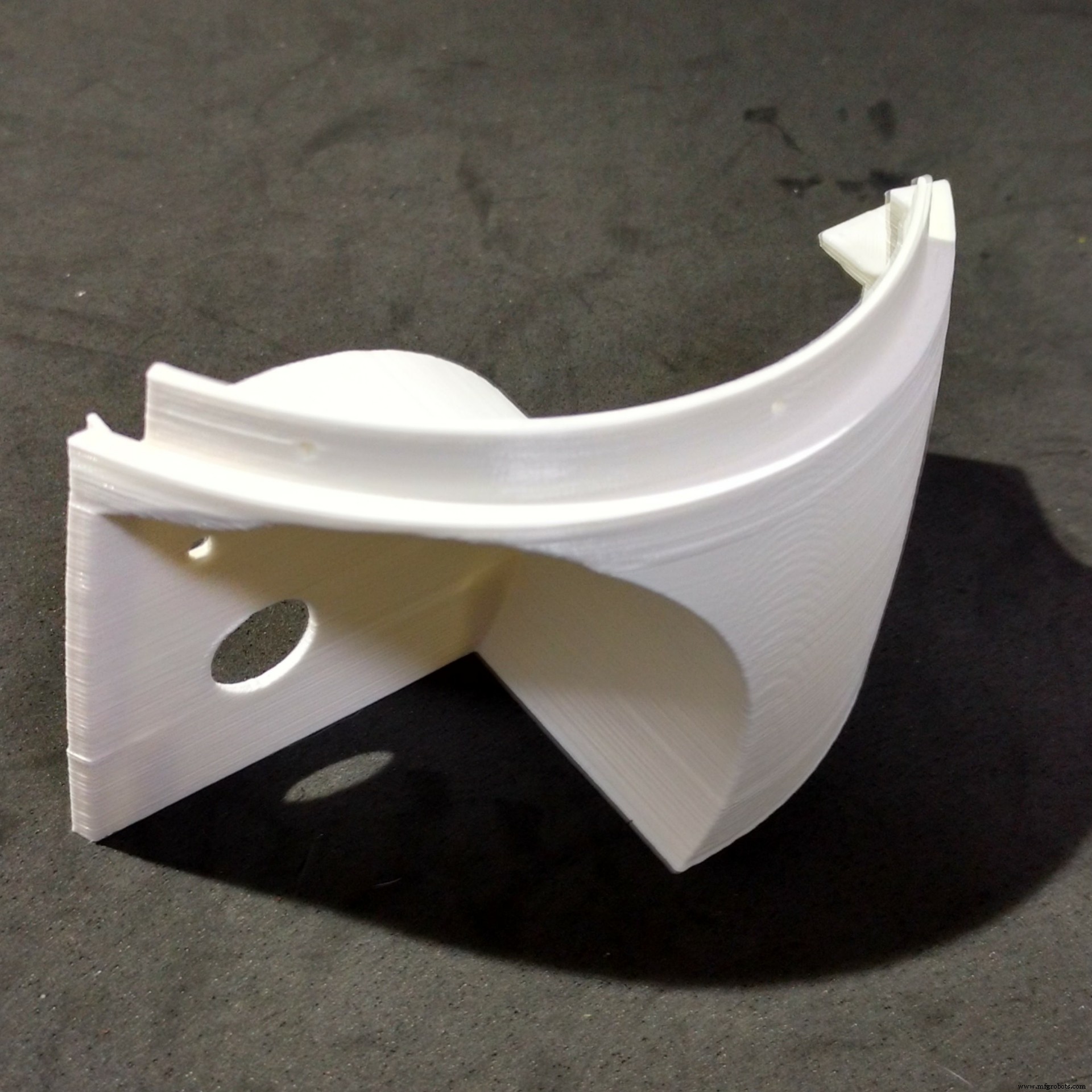
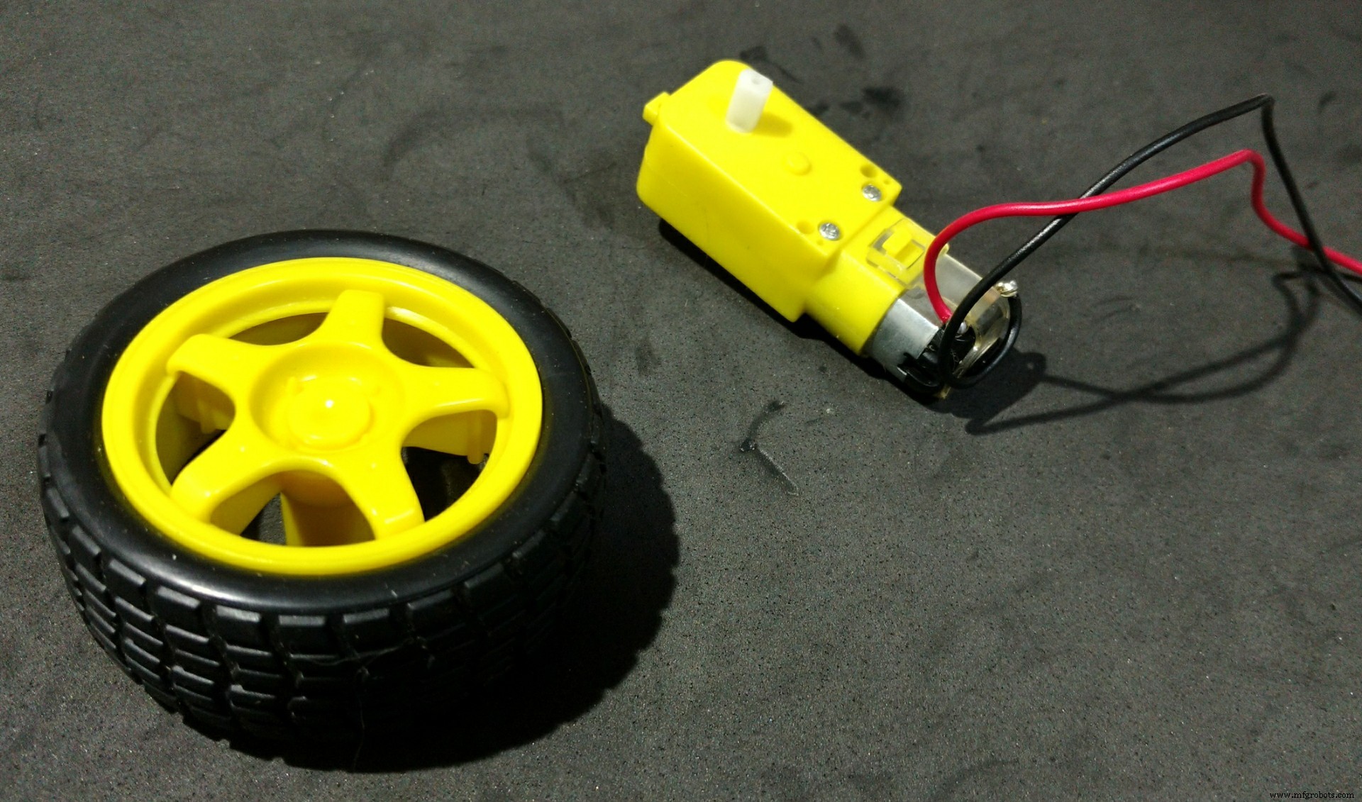

The wheels of the robot uses three 3d printed parts:
- Wheels (left/right)
- Front
It took me around 10h to print those parts.
I followed the following steps for assembling the wheels:
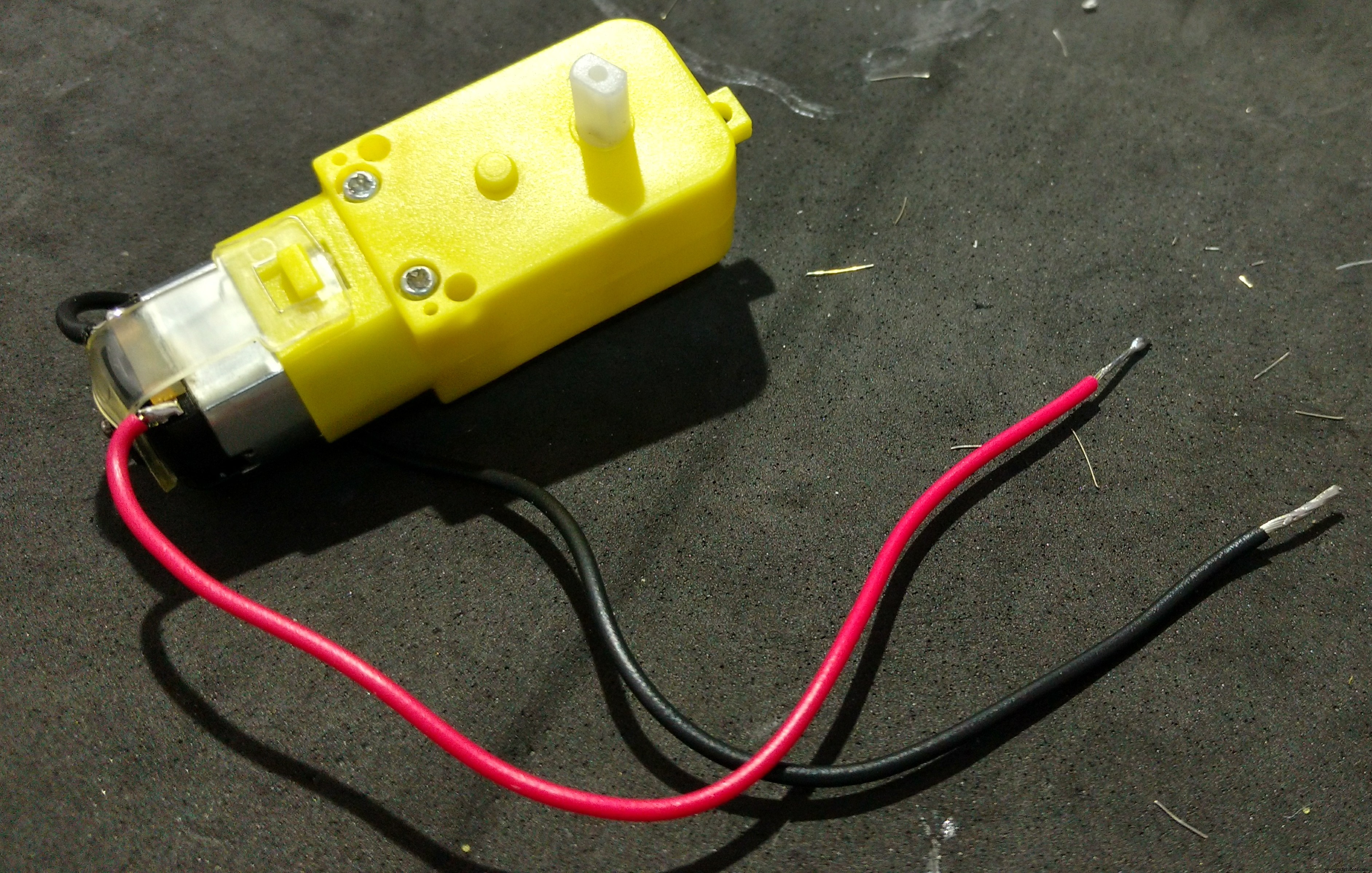
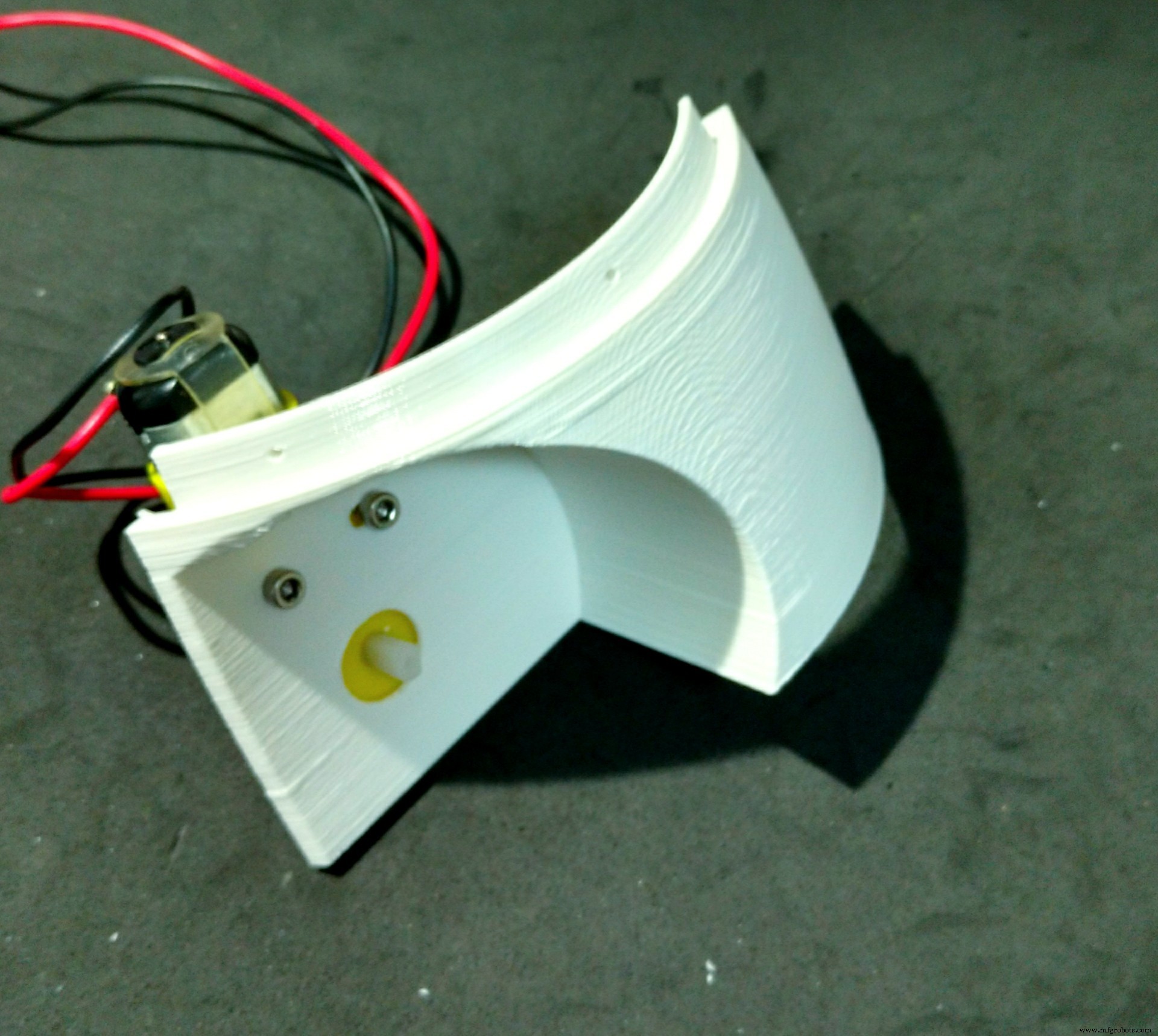
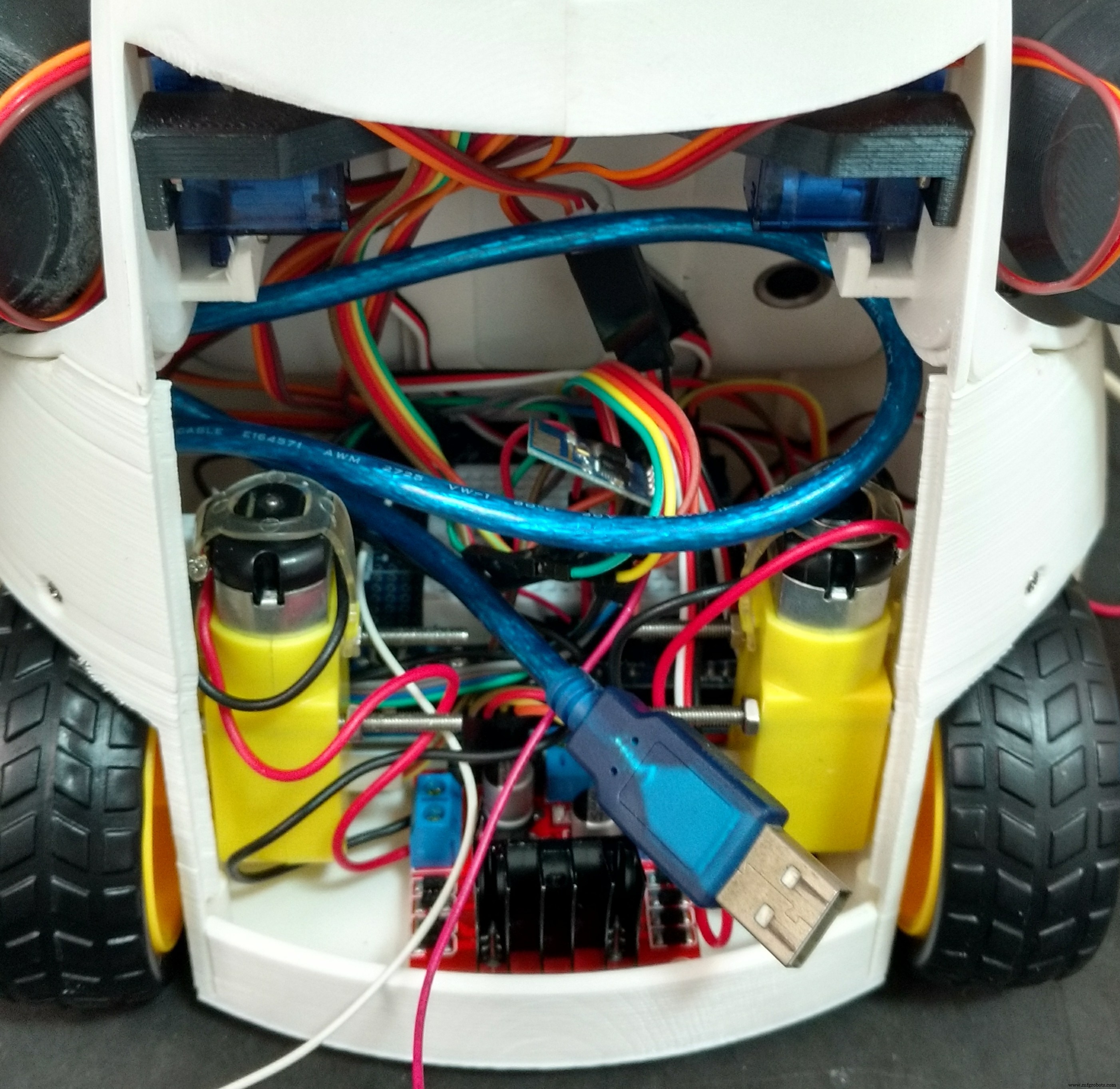
- First I had to solder some wires to DC motors connectors. Those wires were later used for powering the motors using a H-bridge circuit;
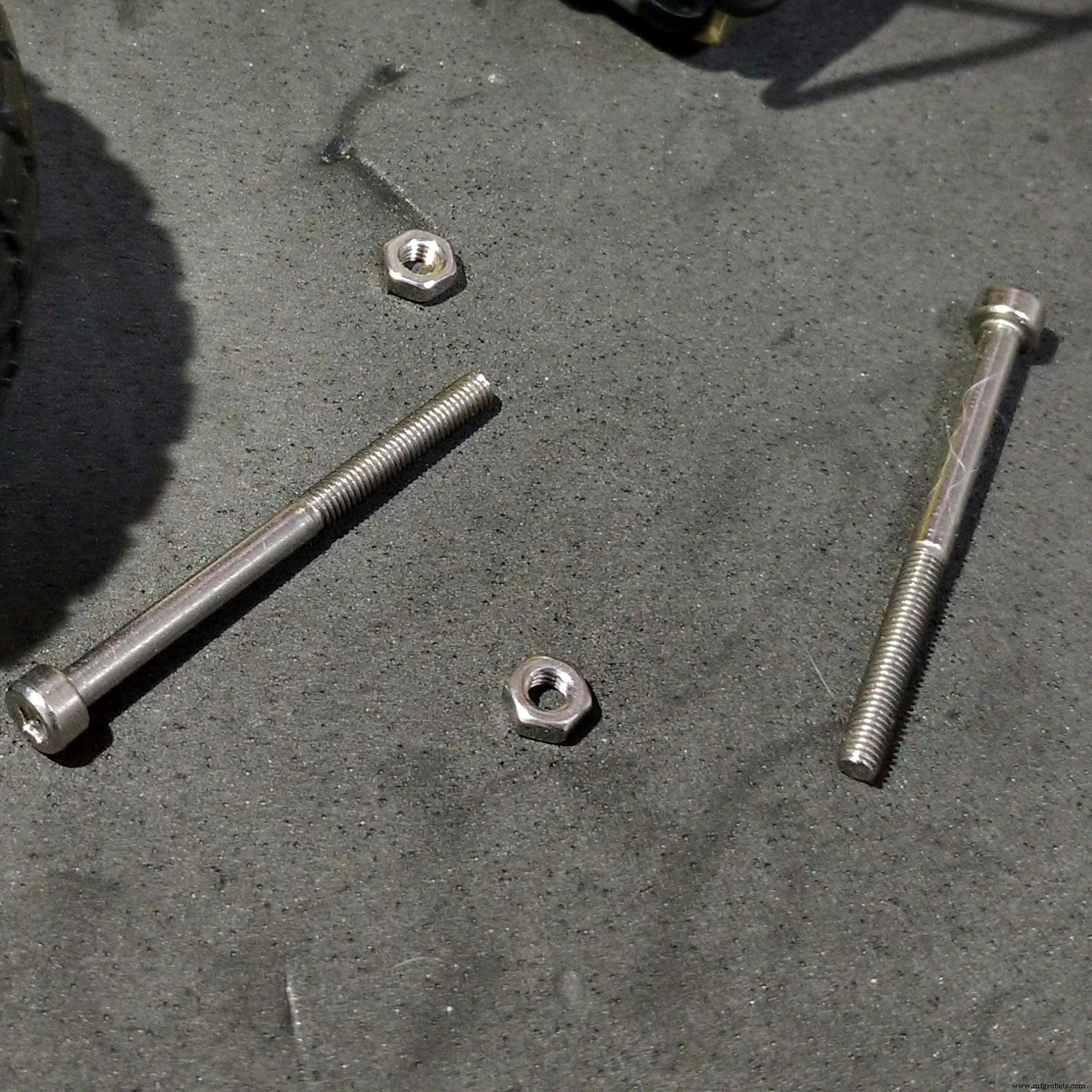
- The motors were then attached to the structure using two M3x40 bolts and nuts for each. Actually a shorter bolt might be used (but I found none online);
- After that I glued the front pannel, which links the other parts of the structure;
- This part has some holes on its top. They are used for its attachment to the chest, shown previously. Six M2x6mm bolts were used for the connection of both sections.
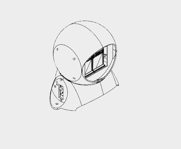
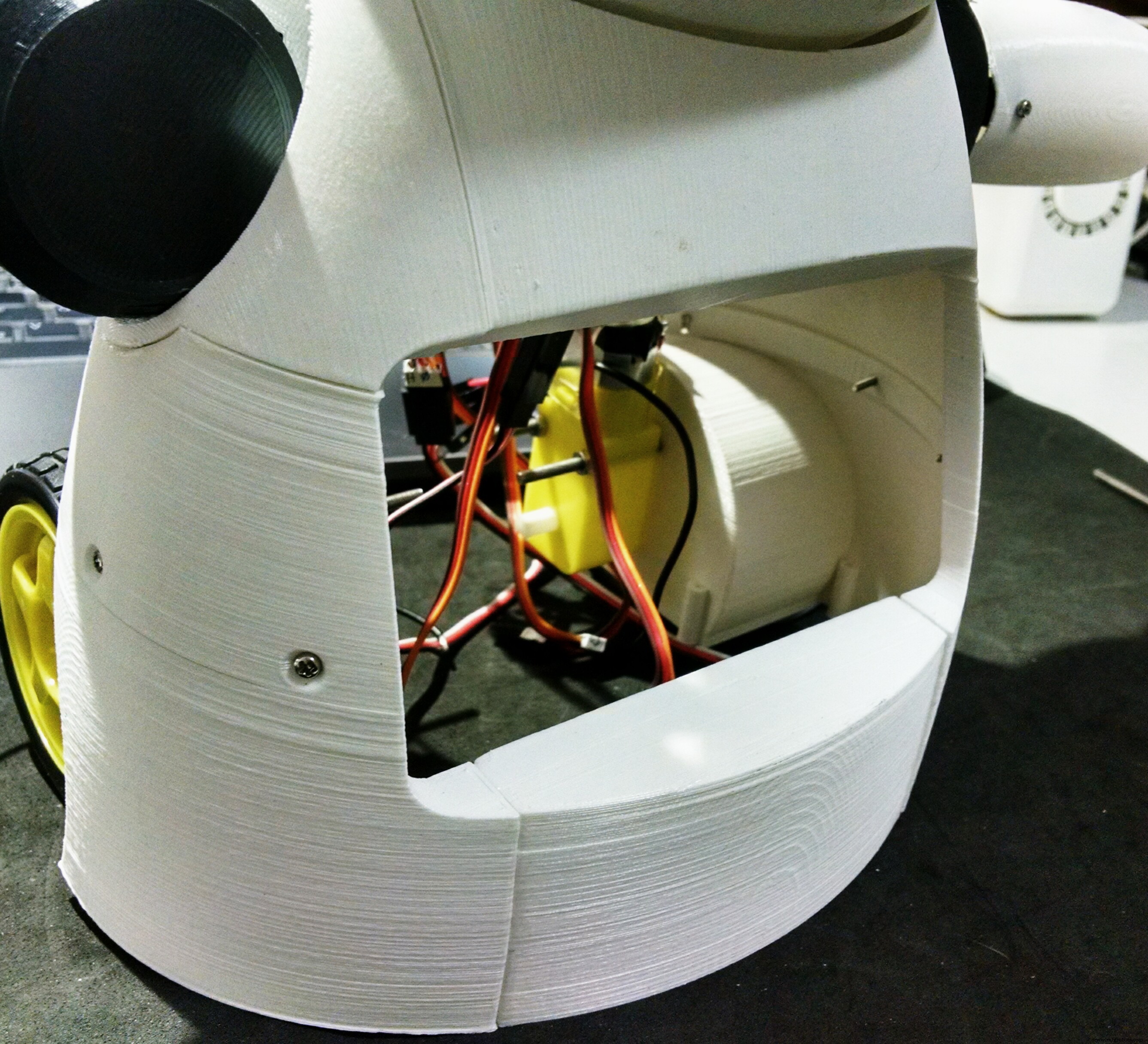
Step 11:Phone Holder
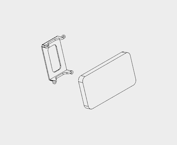

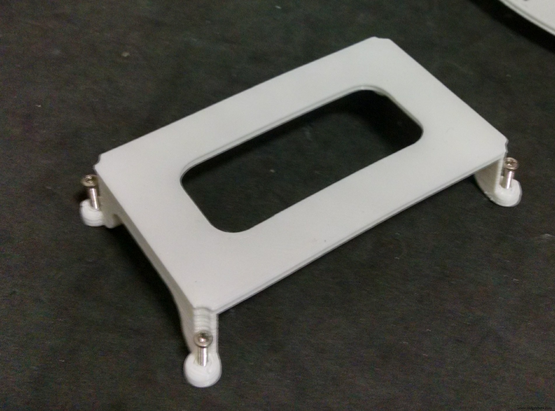
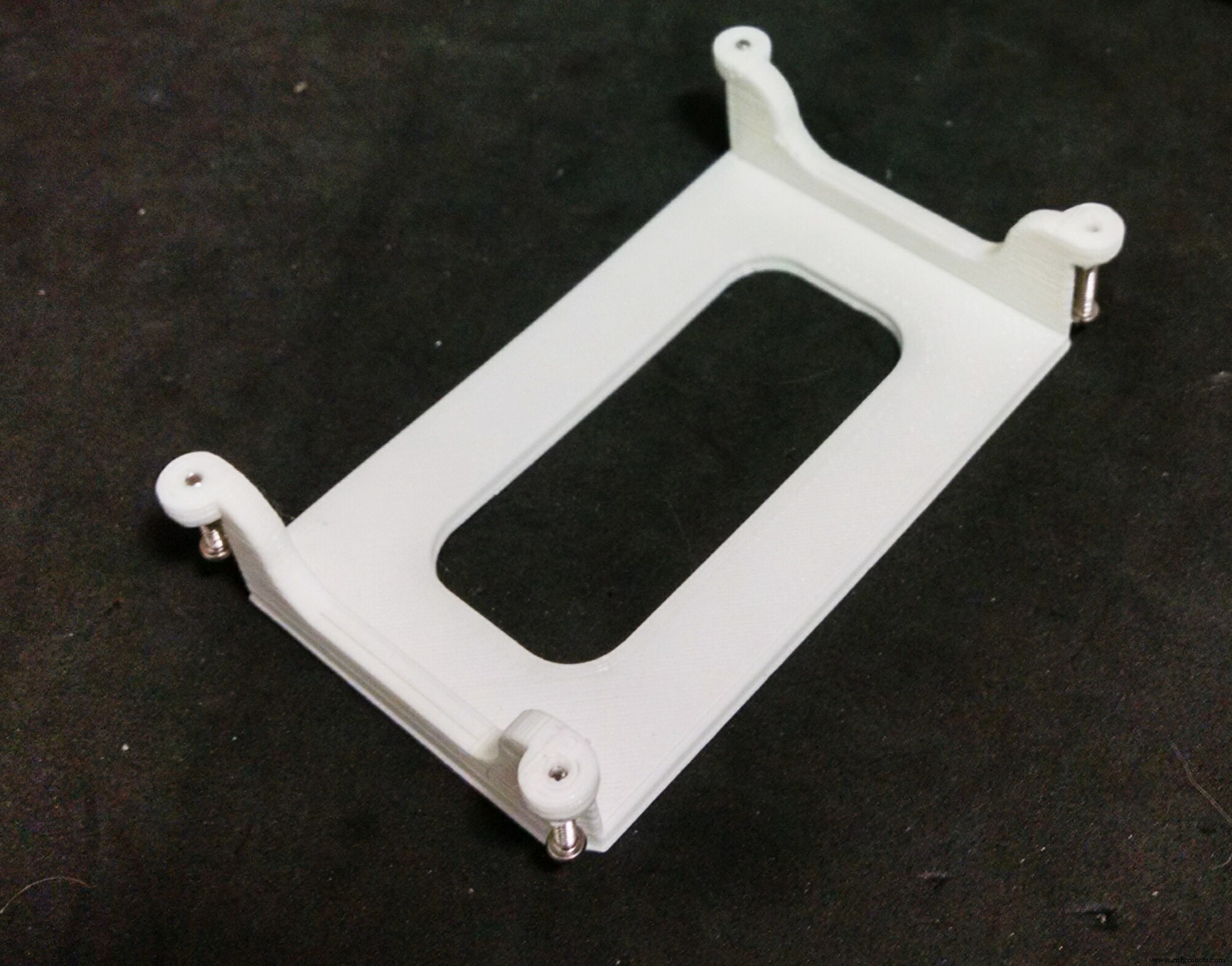
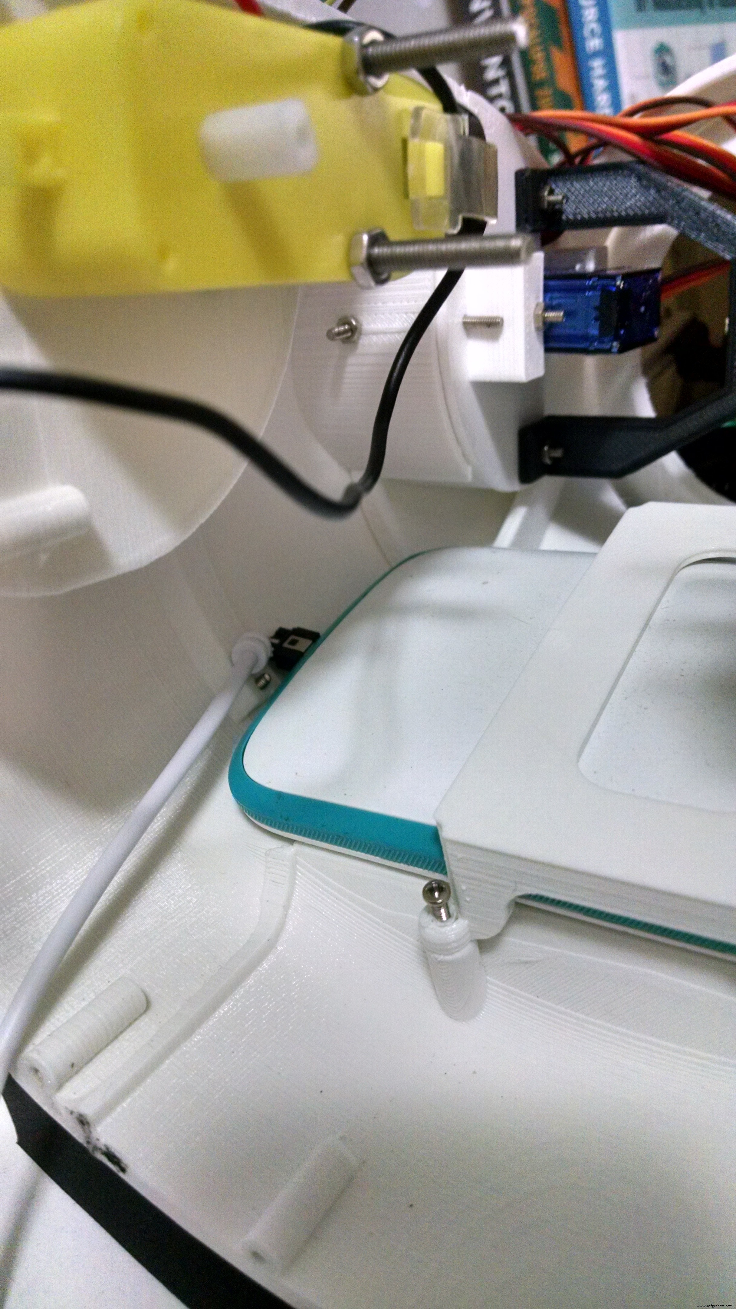
The phone holder is a single 3d printed part, and it takes around 1 hour to print.
The robot has a smartphone at it's belly. It was designed for a Motorola Moto E. It has a 4.3" display. Other smartphones with similar size might fit as well.
The phone holder part is used to hold the smartphone in the desired position. First the smart phone is positioned, then it's pressed against the body of the robot using the phone holder and four M2x6mm bolts.
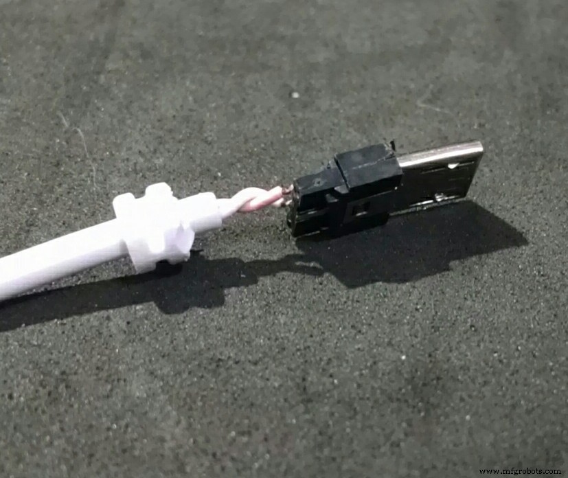
It's importart to connect the USB cabe to the smartphone before tightening the bolts. Otherwise it will be hard to connect it later. Unfortunatly the space is very limited, so I had to cut part of the USB connector away... :/
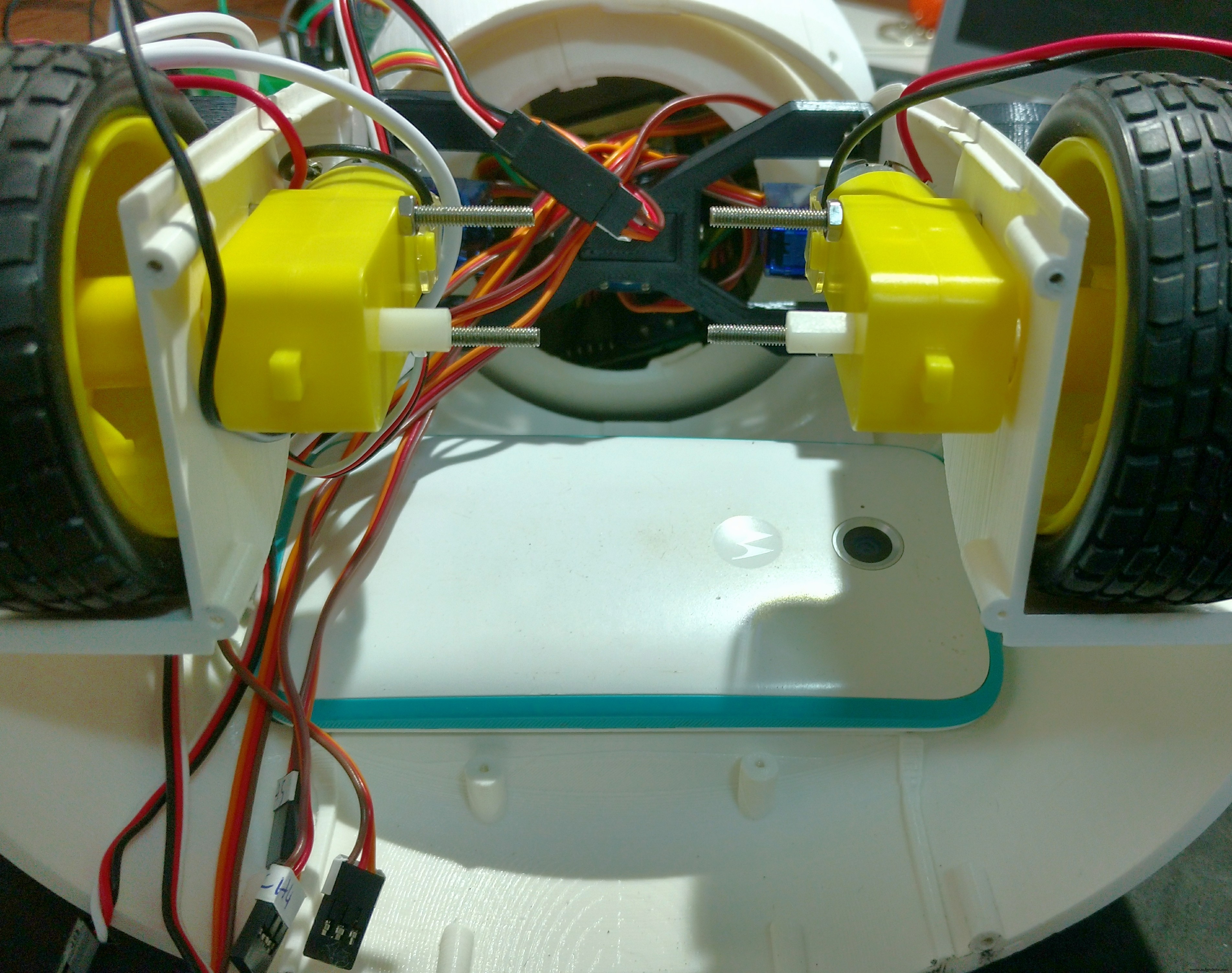
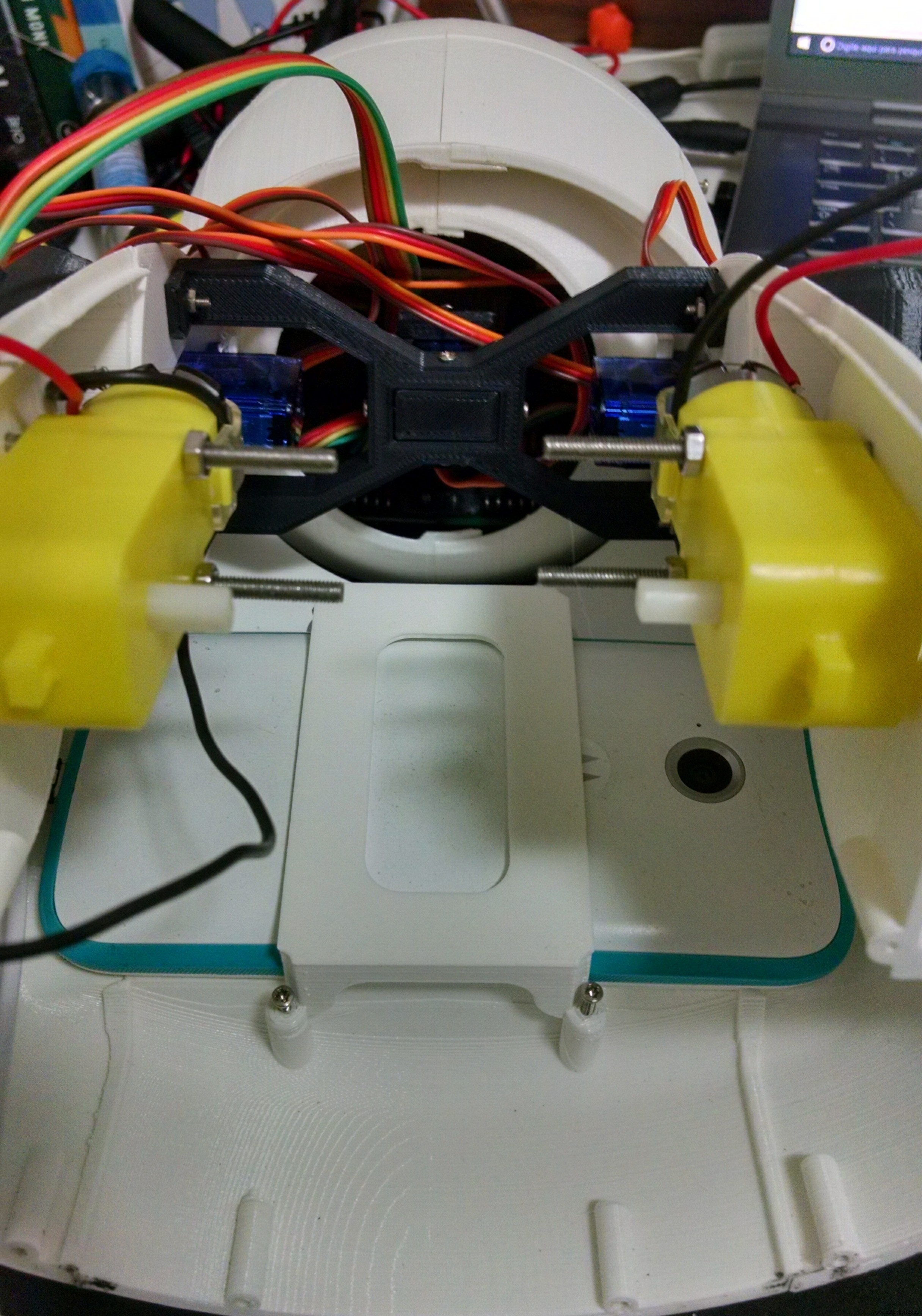
Step 12:Mounting the Base
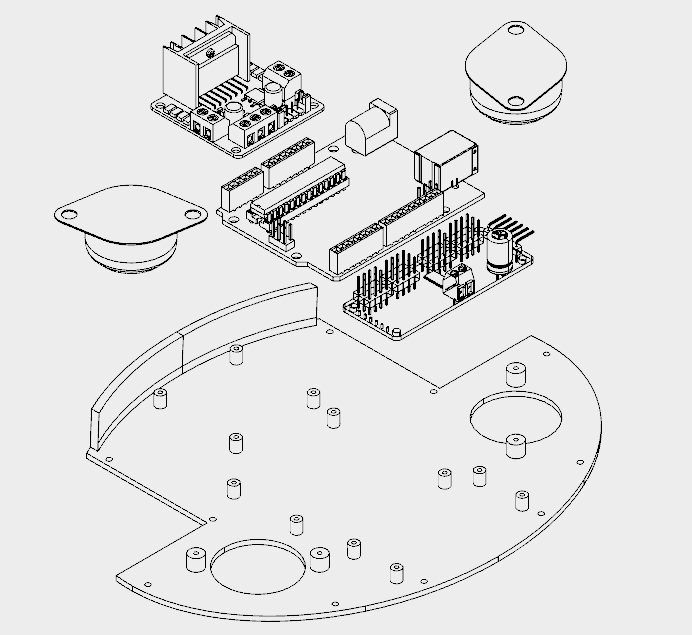
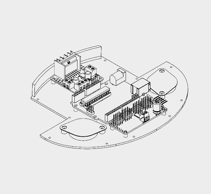
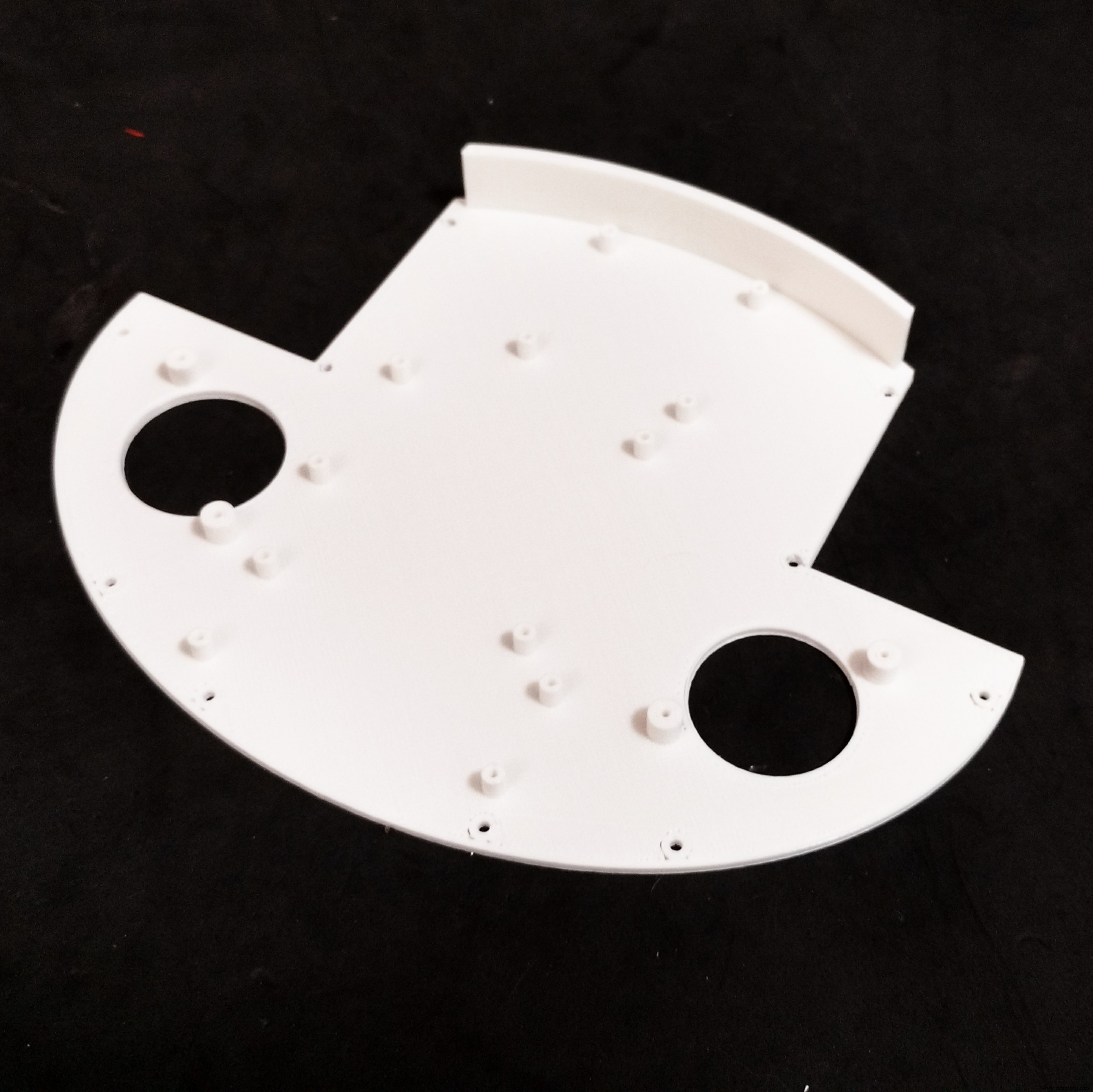
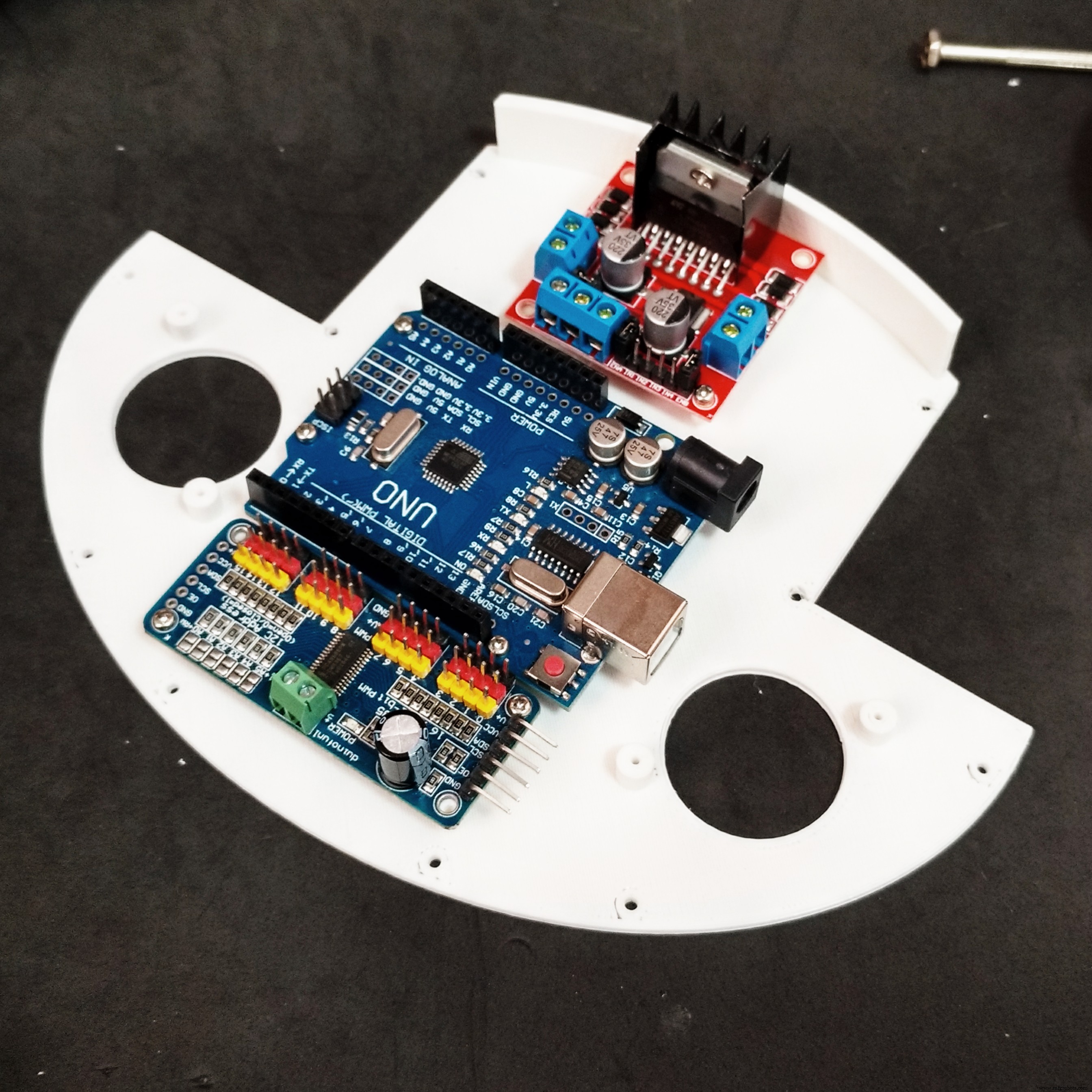
The base has only one 3D printed part. It took me around 4h to print that part.
It has several holes for the installation of other components, like the ball wheels, and circuit boards for instance. The following procedure was used for assembling the base:
- Install the 16 channel servo controller using four M2x6mm bolts;
- Install the L298N h-bridge circuit using four M2x6mm bolts;
- Install the Arduino Uno using four M2x6mm bolts;
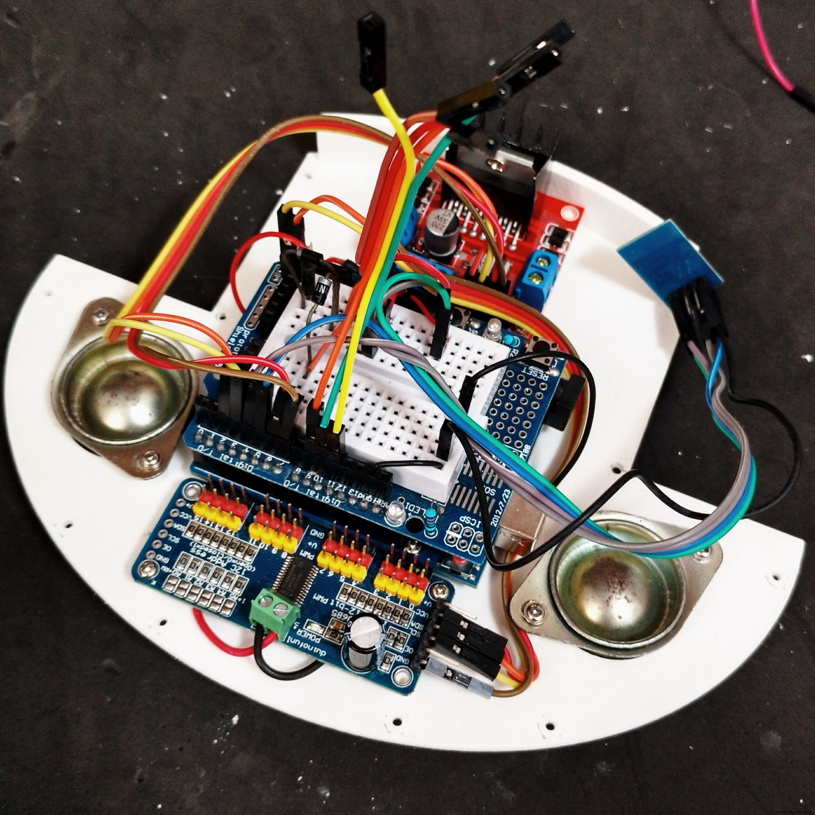
- Install the protoshield on the top of the robot;
- Wire up the circuits (as it's described a couple steps later);
- Installe the ball wheels using two screws for each one. The wires were arranged so that they are traped between the base and the screws used in the installation of the wheels;
- Base was attached to wheels section using some screws.
Step 13:Back and Power Pack
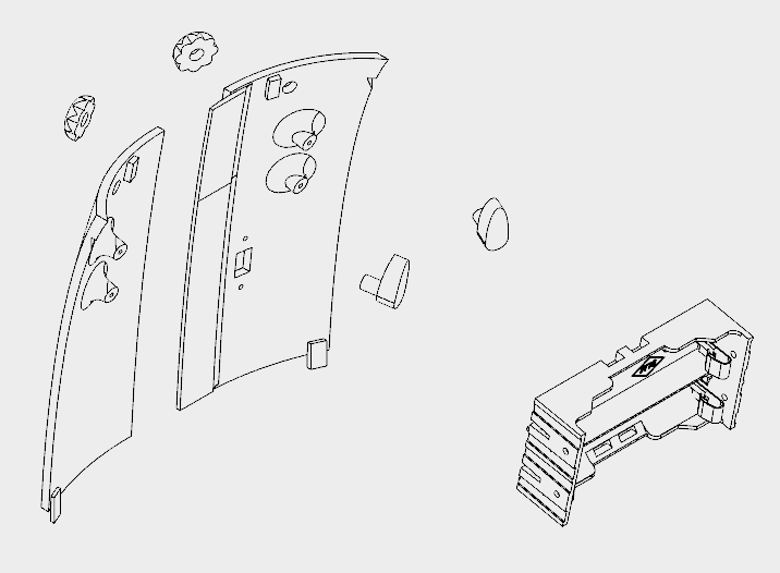


The back cover of the robot was designed so that one can easilly open it for accessing the circuits, recharging the batteries, or turning the smartphone on/off.
It's made of six 3d printed parts:
- Back (left/right)
- Knobs (x2)
- Locks (left/right)
It took me around 5h30 for printing the parts. Right and left back parts were glued using superglue. Wait until the glue is completly dry, or the cover will break easilly.
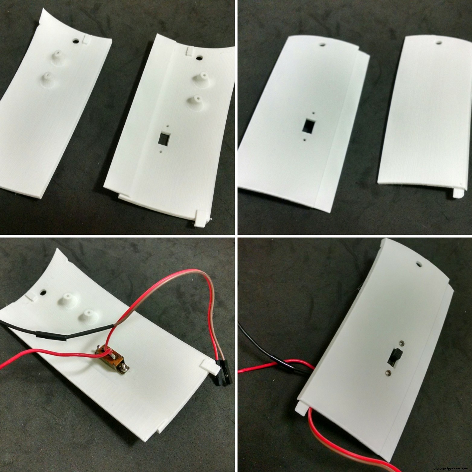
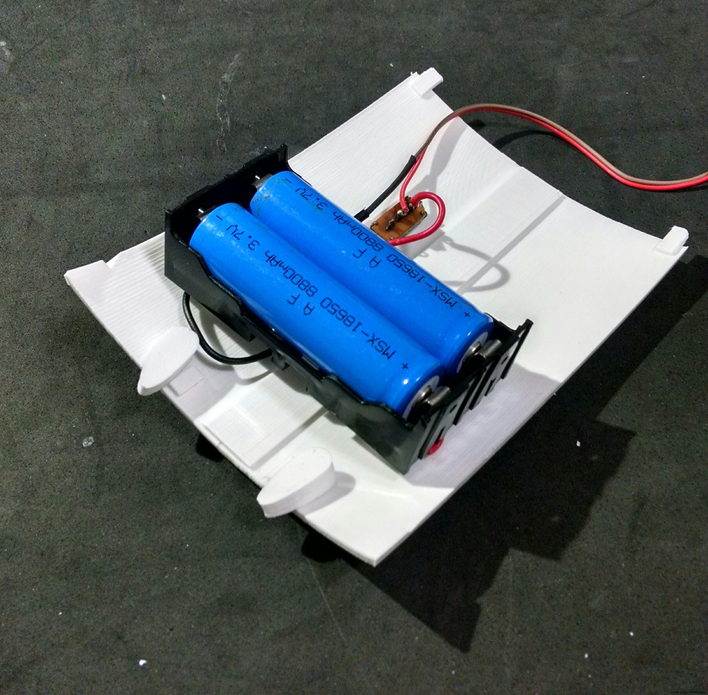
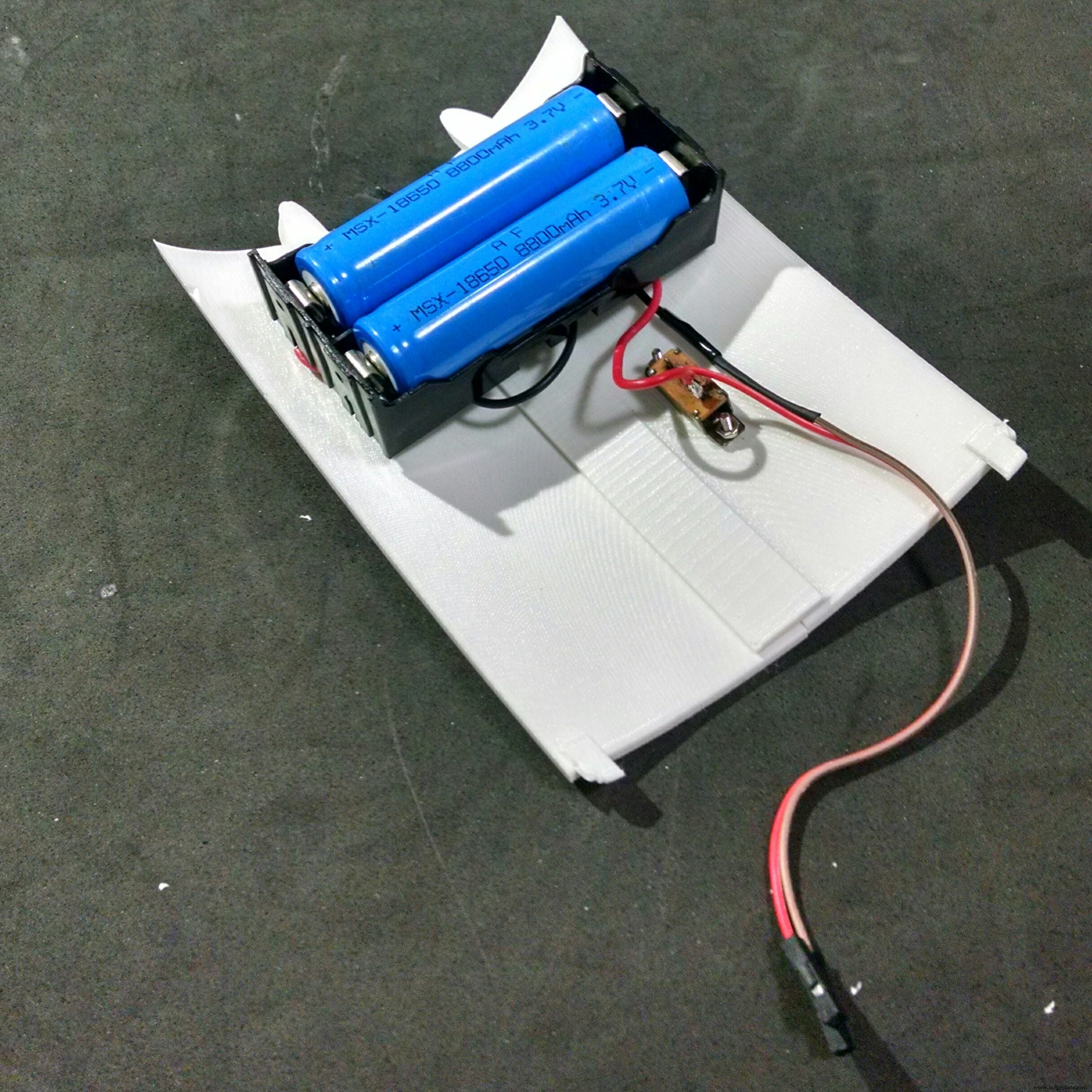
The power pack consists of two 18650 batteries and a battery holder. I had to solder some wires (between battery #1 negative pole and battery #2 positive pole). The negative pole of the power pack was connected to Arduinos GND (using some wires and jumpers). A on/off swich was installed between the positive pole and Arduino's Vin input.
The on/off switch was attached to back 3d printed parts using a M2x6mm bolt and M2x1.5mm nut. The battery holder was attached to the back using four M2x6mm bolts.
The cilindrical part of the locks had to be sanded with a sand paper for a better fitting. They pass through the holes on the cover. The knobs are connected and glued on the other side.
The cover fits to the back of the robot. The knobs can be turned for locking the lid, protecting the insides of the robot.
Step 14:Wiring Up the Circuits

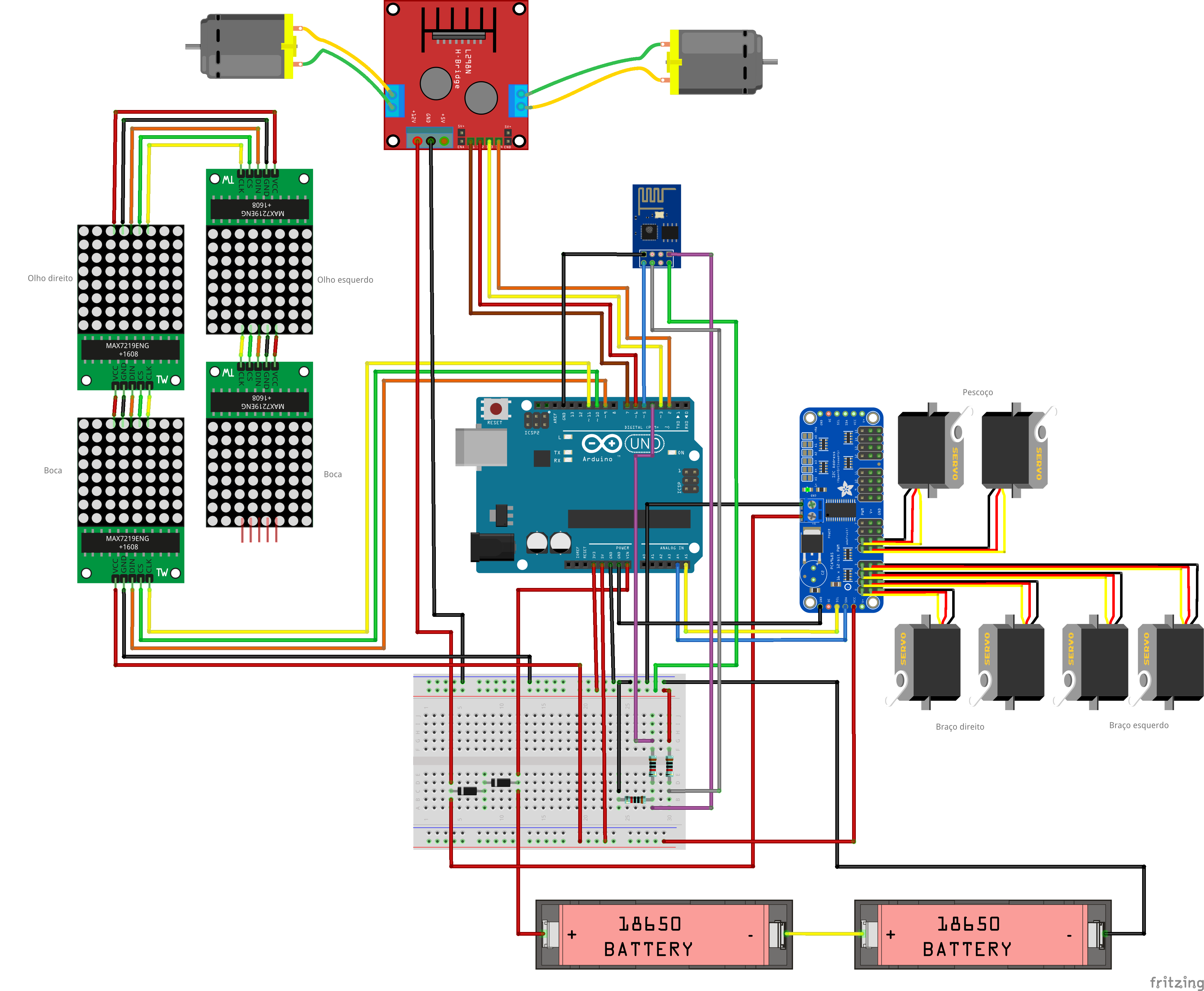
The circuit was wired up according to the schematics.
Arduino:
- Arduino pin D2 => L298N pin IN4
- Arduino pin D3 => L298N pin IN3
- Arduino pin D6 => L298N pin IN2
- Arduino pin D7 => L298N pin IN1
- Arduino pin D9 => MAX7219 pin DIN
- Arduino pin D10 => MAX7219 pin CS
- Arduino pin D11 => MAX7219 pin CLK
- Arduino pin D4 => ESP8266 RXD
- Arduino pin D5 => ESP8266 TXD
- Arduino pin A4 => SDA
- Arduino pin A5 => SCL
- Arduino pin Vin => Battery V+ (before diodes)
- Arduino pin gnd => Battery V-
ESP8266-01
- ESP8266 pin RXD => Arduino pin D4
- ESP8266 pin TXD => Arduino pin D5
- ESP8266 pin gnd => Arduino pin gnd
- ESP8266 pin Vcc => Arduino pin 3V3
- ESP8266 pin CH_PD => Arduino pin 3V3
L298N h-bridge
- L298N pin IN1 => Arduino pin D7
- L298N pin IN2 => Arduino pin D6
- L298N pin IN3 => Arduino pin D3
- L298N pin IN4 => Arduino pin D2
- L298N pin +12V => Battery V+ (after diodes)
- L298N pin gnd => Arduino gnd
- L298N OUT1 => Motor 1
- L298N OUT2 => Motor 2
MAX7219 (first matrix)
- MAX7219 pin DIN => Arduino pin D9
- MAX7219 pin CS => Arduino pin D10
- MAX7219 pin CLK => Arduino pin D11
- MAX7219 pin Vcc => Arduino pin 5V
- MAX7219 pin gnd => Arduino pin gnd
MAX7219 (other matrixes)
- MAX7219 pin DIN => MAX7219 pin DOUT(previous matrix)
- MAX7219 pin CS => MAX7219 pin CS (previous matrix)
- MAX7219 pin CLK => MAX7219 pin CLK (previous matrix)
- MAX7219 pin Vcc => MAX7219 pin VCC (previous matrix)
- MAX7219 pin gnd =:MAX7219 pin gnd (previous matrix)
16-channel servo controller
- Servo controller pin SCL => Arduino pin A5
- Servo controller pin SDA => Arduino pin A4
- Servo controller pin Vcc => Arduino pin 5V
- Servo controller pin gnd => Arduino pin gnd
- Servo controller pin V+ => Battery V+ (after diodes)
- Servo controller pin gnd => Arduino pin gnd
Some say the Sg90 servo can be powered between 3.0 and 6.0V, others between 4.0 and 7.2V. To avoid trouble I decided to put two diodes in series after the batteries. This way, the voltage for servos is 2*3.7 - 2*0.7 =6.0V. The same is applied to the DC motors.
Notice this is not the most efficient way, but it worked for me.
robot%2Bmk0%2B-%2Brev8_bb.pdf robot%2Bmk0%2B-%2Brev8_Esquem_C3_A1tico.pdf
Step 15:Arduino Code
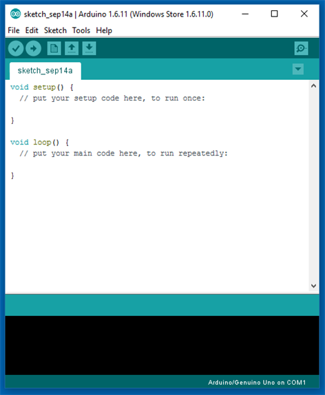

Install the latest Arduino IDE. No library was needed for communication with ESP-8266 module or control of the DC motors.
I'll need to add the following libraries:
- LedControl.h :library used to control the LED matrixes;
- Adafruit_PWMServoDriver.h :library used to control the servo motors.
Arduino code is divided in 9 parts:
- RobodaAlegria.ino: this is the main sketch, and it call the other parts. Libraries are imported here. It also define and initialize global variables;
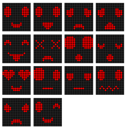
- _05_Def_Olhos.ino: this is where the matrixes for each eye are defined. Each eye is represented by a 8x8 matrix, and 9 options where defined:neutral, wide-eye, closed up, closed down, angry, borred, sad, in love, and dead eyes. There is a different matrix for right and left eyes;
- _06_Def_Boca.ino: this is where the matrices for the mouth are defined. The mouth is represented by a 16x8 matrix, and 9 options where defined:happy, sad, very happy, very sad, neutral, tongue out, open, wide-open, and disgusted mouth;
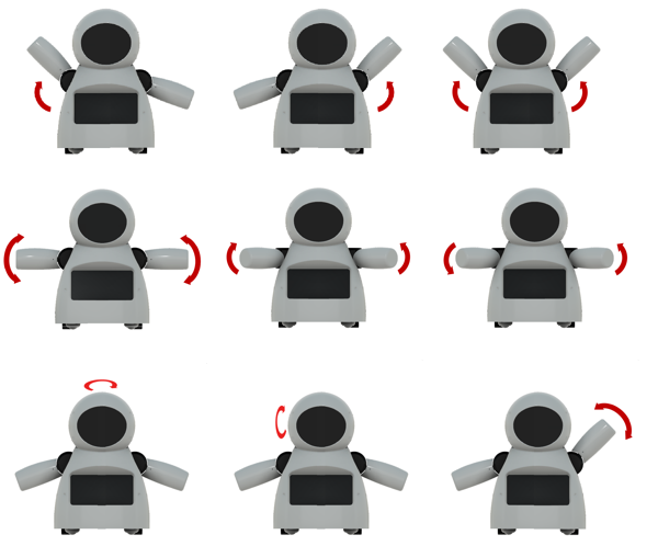
- _10_Bracos.ino: predefined movements for arms and neck are defined in this file. Nine movements, mov1() to mov9(), were configured;
- _12_Rosto.ino: in this file there are some functions for updating the face of the robot, combining the matrixes defined in _05_Def_Olhos.ino and _06_Def_Boca.ino;
- _13_Motores_DC: it defines the functions for ther DC motors;
- _20_Comunicacao.ino: a function for sending data to ESP8266 is defined in this file;
- _80_Setup.ino: it runs on Arduino power up. It set the inicial face and position of the motors of the robot. It also send commands for the connection to a given Wi-Fi network;
- _90_Loop: main loop. It looks for incoming commands from ESP8266 and call specific functions to control the outputs.
Download Arduino code. Replace the XXXXX by your wifi router SSID and YYYYY by router password on on '_80_Setup.ino'. Please check the baudrate of you ESP8266 and set it properly in the code ('_80_Setup.ino'). Connect the Arduino board to your computer USB port and upload the code.
RoboAlegria.rar
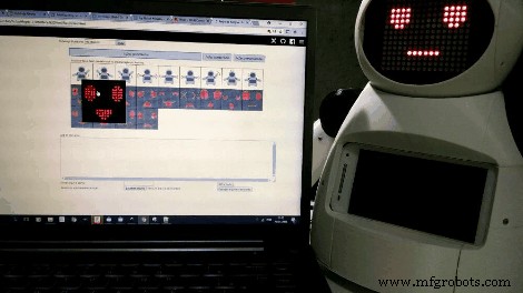
Step 16:Android Apps
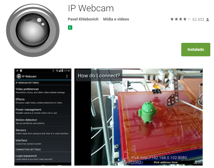
An Android smartphone was used to broadcast the video and audio from the robot to the control interface. You can find the app I used on Google Play store (https://play.google.com/store/apps/details?id=com.pas.webcam).
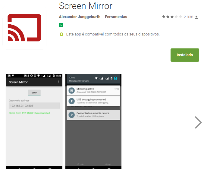
The screen of the smartphone may also be transmited to the control interface, so that the operator can see what's on the screen. You can also find the app I used to mirror the screnn on Google Play store (https://play.google.com/store/apps/details?id=com.ajungg.screenmirror).
An Android video game was also designed to interact with the robot. It's not yet very stable, so it isn't available for download.
Step 17:Control Interface


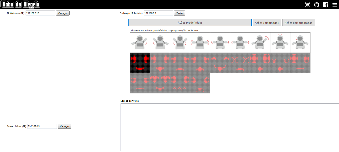
A html interface was designed for the control of the robot.Download interface.rar and extract all the files to a given folder. Then open it on Firefox. The interface is divided in two blocks. To the left there are displays for the camera and screen mirror. To the right there are controll buttons for the commands.
Textbox forms are used in that interface to enter IP address of the ESP8266 module ('Endereço IP Arduino:'), video/audio server from Android IP Webcam app ('IP Webcam (IP):') and Screen Mirror IP address ('Screen Mirror (IP):').
Under 'Ações predefinidas' tab user can select between 9 predefined body movements and 13 different faces. On 'Ações personalizadas' tab user can set a given angles for each of the 6 servos, and individually select between 9 eyes possibilities and 8 mouths variations. A javascript function runs whenever one of those buttons is clicked, and a message is sent for ESP8266's IP address.
Keyboard arrow keys are used for moving the robot forward or backward, and to rotate left or right.
When the interface is started, a warning is displayed, asking if the user wants to share the microphone. If this option is selected, sound intensity of the microphone will be used to send a preconfigured command to the robot. This command will trigger an animation, simulating speech movement on robot's face. A settings button on upper right corner might be used to set the sensitivity of the microphone.
This settings menu might also be used to configure the speed of arms and neck movements.
interface.rar
Step 18:Have Fun
Power it up and have fun!
If you like it, please share this tutorial with you friends! And don't forget to vote on Instructubles Contests! :D
http://www.instructables.com/id/Joy-Robot-Rob%C3%B4-Da-Alegria-Open-Source-3D-Printed-A/
代码
- Arduino 代码
- HTML Interface
Arduino 代码Arduino
无预览(仅限下载)。
HTML InterfaceHTML
无预览(仅限下载)。
Github
https://github.com/wayoda/LedControlhttps://github.com/wayoda/LedControlGithub
https://github.com/adafruit/Adafruit-PWM-Servo-Driver-Libraryhttps://github.com/adafruit/Adafruit-PWM-Servo-Driver-Library定制零件和外壳
Thingiverse
https://www.thingiverse.com/thing:2765192CAD file on thingiverse.comYoumagine
https://www.youmagine.com/designs/joy-robot-robo-da-alegria示意图
制造工艺