

Arduino 颜色传感教程 - TCS230 TCS3200 颜色传感器
在本 Arduino 教程中,我们将学习如何使用 Arduino 和 TCS230 / TCS3200 颜色传感器检测颜色。您可以观看以下视频或阅读下面的书面教程了解更多详情。
TCS230 / TCS3200 颜色传感器的工作原理
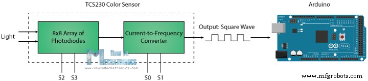
TCS230 在 8 x 8 光电二极管阵列的帮助下感应彩色光。然后使用电流频率转换器将来自光电二极管的读数转换为频率与光强度成正比的方波。最后,使用 Arduino Board 我们可以读取方波输出并获得颜色的结果。
如果我们仔细观察传感器,我们可以看到它是如何检测各种颜色的。光电二极管具有三种不同的滤色器。其中 16 个有红色滤光片,另外 16 个有绿色滤光片,另外 16 个有蓝色滤光片,另外 16 个光电二极管是透明的,没有滤光片。
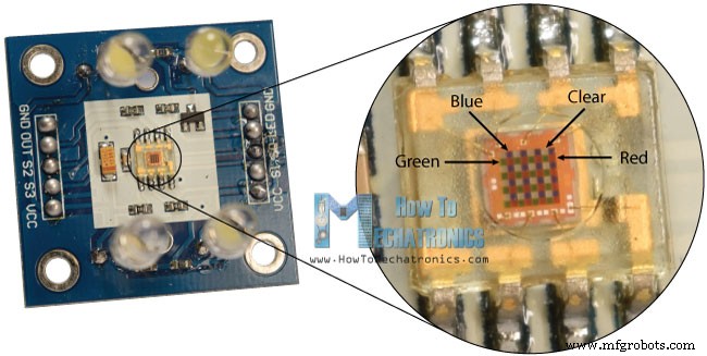
每 16 个光电二极管并联,因此使用两个控制引脚 S2 和 S3,我们可以选择读取其中的哪个。因此,例如,如果我们要检测红色,我们可以使用 16 个红色过滤光电二极管,根据表格将两个引脚设置为逻辑低电平。
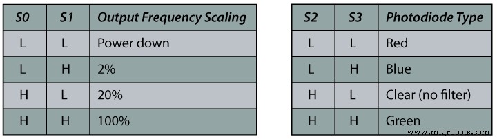
传感器还有两个控制引脚 S0 和 S1,用于缩放输出频率。频率可以缩放为 100 %、20 % 或 2% 三个不同的预设值。这种频率缩放功能允许针对各种频率计数器或微控制器优化传感器的输出。
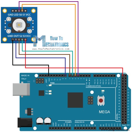
现在我们准备继续并将 TCS230 传感器连接到 Arduino 板。这是电路原理图。
您可以从以下链接获取本 Arduino 教程所需的组件:
- TCS230 TCS3200 颜色传感器……。
- Arduino 开发板………………………………
- 面包板和跳线…………
TCS230 颜色传感器源代码
说明: 首先,我们需要定义传感器连接的引脚并定义一个用于读取频率的变量。在设置部分,我们需要将四个控制引脚定义为输出,将传感器输出定义为 Arduino 输入。这里我们还需要设置频率缩放,在这个例子中我将它设置为 20%,并启动串行通信以在串行监视器中显示结果。
在循环部分,我们将从读取红色过滤光电二极管开始。为此,我们将两个控制引脚 S2 和 S3 设置为低逻辑电平。然后使用“pulseIn()”函数,我们将读取输出频率并将其放入变量“频率”中。使用 Serial.print() 函数,我们将在串行监视器上打印结果。其他两种颜色也一样,我们只需要将控制引脚调整为合适的颜色即可。
/*     Arduino Color Sensing Tutorial
 *
 *  by Dejan Nedelkovski, www.HowToMechatronics.com
 *
 */

#define S0 4
#define S1 5
#define S2 6
#define S3 7
#define sensorOut 8

int frequency = 0;

void setup() {
  pinMode(S0, OUTPUT);
  pinMode(S1, OUTPUT);
  pinMode(S2, OUTPUT);
  pinMode(S3, OUTPUT);
  pinMode(sensorOut, INPUT);

  // Setting frequency-scaling to 20%
  digitalWrite(S0,HIGH);
  digitalWrite(S1,LOW);

  Serial.begin(9600);
}

void loop() {
  // Setting red filtered photodiodes to be read
  digitalWrite(S2,LOW);
  digitalWrite(S3,LOW);
  // Reading the output frequency
  frequency = pulseIn(sensorOut, LOW);
  // Printing the value on the serial monitor
  Serial.print("R= ");//printing name
  Serial.print(frequency);//printing RED color frequency
  Serial.print("  ");
  delay(100);

  // Setting Green filtered photodiodes to be read
  digitalWrite(S2,HIGH);
  digitalWrite(S3,HIGH);
  // Reading the output frequency
  frequency = pulseIn(sensorOut, LOW);
  // Printing the value on the serial monitor
  Serial.print("G= ");//printing name
  Serial.print(frequency);//printing RED color frequency
  Serial.print("  ");
  delay(100);

  // Setting Blue filtered photodiodes to be read
  digitalWrite(S2,LOW);
  digitalWrite(S3,HIGH);
  // Reading the output frequency
  frequency = pulseIn(sensorOut, LOW);
  // Printing the value on the serial monitor
  Serial.print("B= ");//printing name
  Serial.print(frequency);//printing RED color frequency
  Serial.println("  ");
  delay(100);
}Code language: Arduino (arduino)
现在,如果我们运行串行监视器,我们将开始获取一些值。这些值取决于所选的频率缩放,以及来自周围的照明。
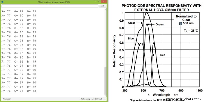
请注意,由于每种光电二极管类型的灵敏度不同,三个值会有所不同,如传感器数据表中的光电二极管光谱响应度图所示。
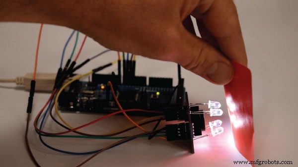
尽管如此,现在让我们看看当我们将不同的颜色带到传感器前面时,这些值是如何反应的。所以举个例子,如果我们带红色,初始值会下降,在我的例子中是从 70 到 25 左右。
所以现在如果我们想用值从 0 到 255 的 RGB 模型来表示检测到的颜色,我们将使用 map() 函数将读数映射或转换为 0 到 255 的值。
//Remaping the value of the frequency to the RGB Model of 0 to 255
  frequency = map(frequency, 25,70,255,0);
70 的值将映射为 0,25 的值将映射为 255。同样的过程适用于其他两种颜色。
这是此示例的最终源代码:
/*     Arduino Color Sensing Tutorial
 *
 *  by Dejan Nedelkovski, www.HowToMechatronics.com
 *
 */

#define S0 4
#define S1 5
#define S2 6
#define S3 7
#define sensorOut 8

int frequency = 0;

void setup() {
  pinMode(S0, OUTPUT);
  pinMode(S1, OUTPUT);
  pinMode(S2, OUTPUT);
  pinMode(S3, OUTPUT);
  pinMode(sensorOut, INPUT);

  // Setting frequency-scaling to 20%
  digitalWrite(S0,HIGH);
  digitalWrite(S1,LOW);

  Serial.begin(9600);
}

void loop() {
  // Setting red filtered photodiodes to be read
  digitalWrite(S2,LOW);
  digitalWrite(S3,LOW);
  // Reading the output frequency
  frequency = pulseIn(sensorOut, LOW);
  //Remaping the value of the frequency to the RGB Model of 0 to 255
  frequency = map(frequency, 25,72,255,0);
  // Printing the value on the serial monitor
  Serial.print("R= ");//printing name
  Serial.print(frequency);//printing RED color frequency
  Serial.print("  ");
  delay(100);

  // Setting Green filtered photodiodes to be read
  digitalWrite(S2,HIGH);
  digitalWrite(S3,HIGH);
  // Reading the output frequency
  frequency = pulseIn(sensorOut, LOW);
  //Remaping the value of the frequency to the RGB Model of 0 to 255
  frequency = map(frequency, 30,90,255,0);
  // Printing the value on the serial monitor
  Serial.print("G= ");//printing name
  Serial.print(frequency);//printing RED color frequency
  Serial.print("  ");
  delay(100);

  // Setting Blue filtered photodiodes to be read
  digitalWrite(S2,LOW);
  digitalWrite(S3,HIGH);
  // Reading the output frequency
  frequency = pulseIn(sensorOut, LOW);
  //Remaping the value of the frequency to the RGB Model of 0 to 255
  frequency = map(frequency, 25,70,255,0);
  // Printing the value on the serial monitor
  Serial.print("B= ");//printing name
  Serial.print(frequency);//printing RED color frequency
  Serial.println("  ");
  delay(100);
}Code language: Arduino (arduino)
请注意,颜色不是那么准确,但对于简单的项目来说仍然足够好。在我的下一个视频中,作为 TCS230 颜色传感器的另一个示例,我们将学习如何制作 Arduino 自动色选机。

随时在下面的评论部分提出任何问题,不要忘记查看我收集的 Arduino 项目。
制造工艺