

Arduino 色选机项目
在本文中,我将向您展示如何制作 Arduino 色选机。您可以观看以下视频或阅读下面的书面文章。
对于这个 Arduino 项目,我们只需要一个颜色传感器 (TCS3200) 和两个业余爱好者伺服电机,这使得这个项目非常简单,但构建它却非常有趣。首先,我使用Solidworks 3D建模软件设计了色选机,其工作原理如下:
您可以在此处下载 3D 模型以及构建此 Arduino 项目所需的所有尺寸的图纸。
您可以找到并下载此 3D 模型,也可以在 Thangs 上的浏览器中进行探索。
在 Thangs 下载装配 3D 模型。
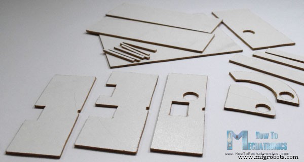
以下图纸可用于激光切割机箱的所有零件:
我用于这个项目的材料是 3 毫米刻度纤维板。我根据图纸在纤维板上重新绘制零件,并使用小手锯将所有零件切割成尺寸。
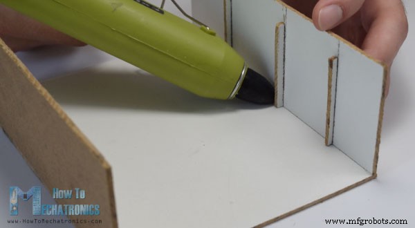
准备好所有零件后,我开始组装它们。首先我用胶枪组装了外部零件。
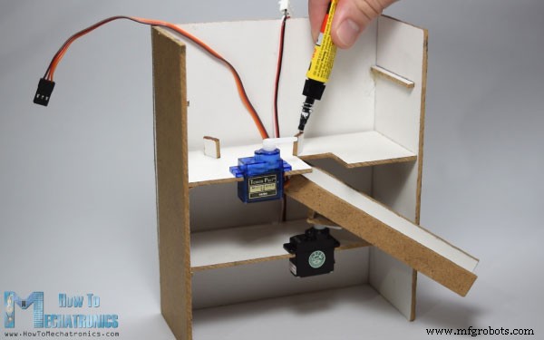
然后使用万能胶将两个伺服电机粘在它们的平台上,并将它们连接到组件上。
之后再次使用胶水将导轨连接到底部伺服电机以及顶部伺服电机所需的支撑和平台。
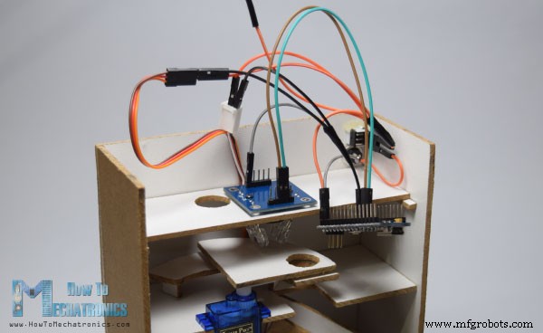
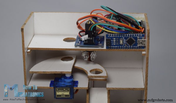
接下来,我插入了一个开关和一个电源插孔,用于使用 5V 适配器为 Arduino 供电,并在第三个平台上插入了颜色传感器。
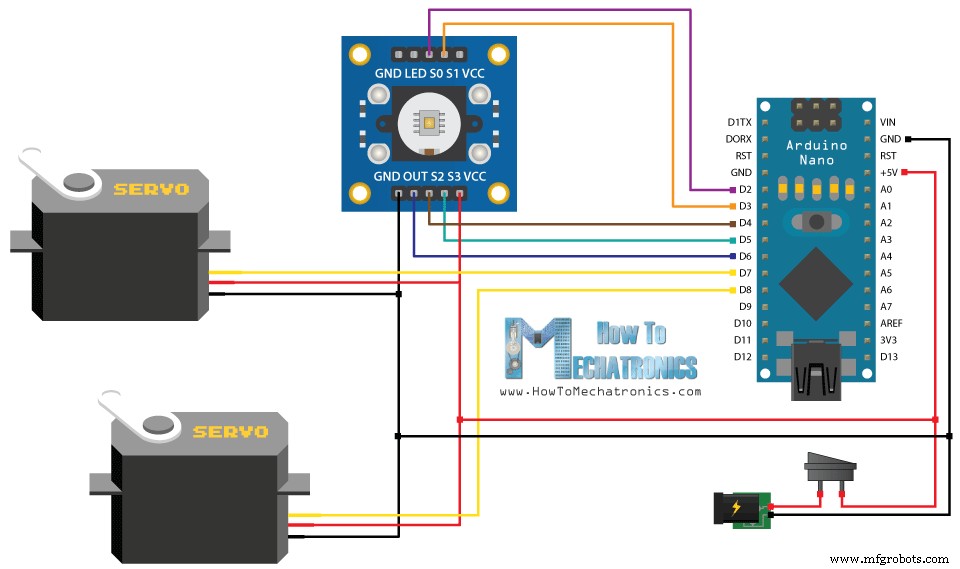
我根据以下电路原理图将组件连接在一起。
您可以从以下链接获取此 Arduino 项目所需的组件:
此时,首先我们需要对 Arduino 进行编程,然后完成组装。这是 Arduino 代码:
代码说明:
因此,我们需要包含“Servo.h”库,定义颜色传感器将连接到的引脚,创建伺服对象并声明程序所需的一些变量。在设置部分,我们需要将引脚定义为输出和输入,设置颜色传感器的频率缩放,定义伺服引脚并启动串行通信以在串行监视器上打印颜色读取的结果。
在循环部分,我们的程序首先将顶部伺服电机移动到吃喝玩乐充电器的位置。注意这个值 115 适合我的零件和我的伺服电机,所以你应该根据你的构建调整这个值以及伺服电机的以下值。
接下来使用“for”循环,我们将旋转并将吃喝玩乐带到颜色传感器的位置。我们使用了一个“for”循环,这样我们就可以通过改变循环中的延迟时间来控制旋转的速度。
接下来,半秒延迟后,使用自定义函数 readColor() 我们将读取彩虹糖的颜色。这是自定义函数的代码。使用颜色传感器的四个控制引脚和频率输出引脚,我们读取了吃喝玩乐的颜色。传感器为每个吃喝玩乐读取 3 个不同的值,红色、绿色和蓝色,根据这些值我们知道实际颜色是什么。有关 TCS3200 颜色传感器工作原理的更多详细信息,您可以查看我之前的详细教程。
这是我从传感器获得的每个吃喝玩乐的 RGB 值。请注意,这些值可能会有所不同,因为传感器并不总是准确的。因此,使用这些“if”语句,我们允许传感器对特定颜色的测试值产生大约 +-5 的误差。例如,如果我们有一个红色的彩虹糖,第一个“if”语句将为真,变量“color”将得到值 1。这就是 readColor() 自定义函数所做的事情,然后使用“switch-case” ”声明我们将底部伺服旋转到特定位置。最后我们进一步旋转顶部伺服电机,直到吃喝玩乐落入导轨,并再次将其送回初始位置,以便重复该过程。
上传代码后,我用胶枪固定了 Arduino 板。
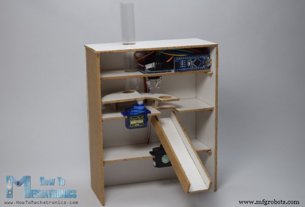
然后我用一个透明的塑料瓶制作了充电器,并与顶部一起将其粘在一起组装并完成了项目。
欢迎在下方评论区提出任何问题。设计


构建 Arduino 颜色分类器
Arduino 色选机源代码
/*     Arduino Project - Color Sorting Machine
 *
 *  by Dejan Nedelkovski, www.HowToMechatronics.com
 *
 */
#include <Servo.h>

#define S0 2
#define S1 3
#define S2 4
#define S3 5
#define sensorOut 6

Servo topServo;
Servo bottomServo;

int frequency = 0;
int color=0;

void setup() {
  pinMode(S0, OUTPUT);
  pinMode(S1, OUTPUT);
  pinMode(S2, OUTPUT);
  pinMode(S3, OUTPUT);
  pinMode(sensorOut, INPUT);

  // Setting frequency-scaling to 20%
  digitalWrite(S0, HIGH);
  digitalWrite(S1, LOW);

  topServo.attach(7);
  bottomServo.attach(8);

  Serial.begin(9600);
}

void loop() {

  topServo.write(115);
  delay(500);

  for(int i = 115; i > 65; i--) {
    topServo.write(i);
    delay(2);
  }
  delay(500);

  color = readColor();
  delay(10);

  switch (color) {
    case 1:
    bottomServo.write(50);
    break;

    case 2:
    bottomServo.write(75);
    break;

    case 3:
    bottomServo.write(100);
    break;

    case 4:
    bottomServo.write(125);
    break;

    case 5:
    bottomServo.write(150);
    break;

    case 6:
    bottomServo.write(175);
    break;

    case 0:
    break;
  }
  delay(300);

  for(int i = 65; i > 29; i--) {
    topServo.write(i);
    delay(2);
  }
  delay(200);

  for(int i = 29; i < 115; i++) {
    topServo.write(i);
    delay(2);
  }
  color=0;
}

// Custom Function - readColor()
int readColor() {
  // Setting red filtered photodiodes to be read
  digitalWrite(S2, LOW);
  digitalWrite(S3, LOW);
  // Reading the output frequency
  frequency = pulseIn(sensorOut, LOW);
  int R = frequency;
  // Printing the value on the serial monitor
  Serial.print("R= ");//printing name
  Serial.print(frequency);//printing RED color frequency
  Serial.print("  ");
  delay(50);

  // Setting Green filtered photodiodes to be read
  digitalWrite(S2, HIGH);
  digitalWrite(S3, HIGH);
  // Reading the output frequency
  frequency = pulseIn(sensorOut, LOW);
  int G = frequency;
  // Printing the value on the serial monitor
  Serial.print("G= ");//printing name
  Serial.print(frequency);//printing RED color frequency
  Serial.print("  ");
  delay(50);

  // Setting Blue filtered photodiodes to be read
  digitalWrite(S2, LOW);
  digitalWrite(S3, HIGH);
  // Reading the output frequency
  frequency = pulseIn(sensorOut, LOW);
  int B = frequency;
  // Printing the value on the serial monitor
  Serial.print("B= ");//printing name
  Serial.print(frequency);//printing RED color frequency
  Serial.println("  ");
  delay(50);

  if(R<45 & R>32 & G<65 & G>55){
    color = 1; // Red
  }
  if(G<55 & G>43 & B<47 &B>35){
    color = 2; // Orange
  }
  if(R<53 & R>40 & G<53 & G>40){
    color = 3; // Green
  }
  if(R<38 & R>24 & G<44 & G>30){
    color = 4; // Yellow
  }
  if(R<56 & R>46 & G<65 & G>55){
    color = 5; // Brown
  }
  if (G<58 & G>45 & B<40 &B>26){
    color = 6; // Blue
  }
  return color;
}Code language: Arduino (arduino)
完成设计
制造工艺