

高炉渣及其在高炉运行中的作用
高炉渣及其在高炉运行中的作用
高炉 (BF) 炉渣在实现高炉平稳运行方面的重要性,正如古语所说的“如果你照顾好炉渣,炉子就会照顾其余的人”。已经对 BF 炉渣进行了大量工作,研究了炉渣的性质、形成机制以及对炉子操作的影响。优质的炉渣是高炉生产优质铁水的必要条件。
高炉渣实践需要满足高炉高效运行的一定要求。这些要求包括 (i) 吸收炉料中所有未还原的非挥发性成分并将其从高炉中除去,(ii) 为低粘度液体,(iii) 能够吸收硫主要包含在燃料中, (iv) 为了提高铁水的产量,氧化铁的含量应尽可能少, (v) 在不影响脱硫的情况下,其体积应尽可能低, ( vi) 为确保料柱具有更好的渗透性,炉料组分变得粘合的温度范围应较窄,和 (vii) 其质量应使其能够加工成可销售的材料。这些要求部分是互补的,部分是相互排斥的。因此有必要说明优先事项。
幸运的是,有一些一般关系可以更实际地了解可以每天使用的炉渣性质。然而,重要的是要对高炉渣的基本性质有一个基本的了解,以了解一般关系。
高炉渣的基本原理
高炉渣的基本原理很复杂。氧含量约为 40%,是炉渣中最大的单一元素。因此,炉渣本质上是一种氧化物系统和离子型。由于 BF 工艺的性质,熔渣形成是一个多步骤过程,涉及成分和温度的显着变化。高炉渣的四种主要成分是 SiO2(二氧化硅)、CaO(石灰)、MgO(氧化镁)和 Al2O3(氧化铝)。高炉渣的这四种成分形成了许多化合物,从而产生了广泛的化学和物理特性。渣中较少的成分对铁水化学和炉子控制特别感兴趣,这增加了渣物理化学性质的复杂性。
高炉渣的基础包括与高炉工艺相关的问题。这些问题包括熔渣的形成、炉膛内的流动、熔渣的分子结构以及该结构与碱度、熔渣凝固等化学指标之间的关系,以及熔炉热状态变化对熔渣成分的影响。
熔渣形成 – BF 是加压、逆流换热、回流、气-固-液填充床反应器。它具有三个主要功能,即 (i) 将氧化铁还原为金属铁 (ii) 金属铁和氧化物的熔融,这提供了 (iii) 将炉料和燃料中的杂质与液态铁分离。该工艺的这些特征导致炉子分为三个垂直区域,与熔渣有关:(i) 即 (i) 颗粒区、(ii) 熔渣形成区和 (iii) 炉膛区。这三个区域以及每个区域的一些具体反应如图1所示。
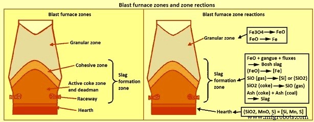
图 1 高炉区域和区域反应
颗粒区位于炉子的上部,所有带电组分都处于固相状态。颗粒区由顶部的储料线和底部的液相形成开始即内聚区界定。随着炉料通过颗粒区下降,它被来自炉子下部的气体加热,部分氧化铁被还原。颗粒区的还原量与含铁材料的性质、炉料分布、气体成分和流动模式有关。
熔渣形成区开始于粘性区,炉料开始软化,并继续下降到风口高度以下。因此,渣形成区包括内聚区、活性焦炭区、死区和滚道。在成渣区上部形成的熔渣称为“炉渣”或“初级”熔渣,离开底部区域的熔渣称为“炉膛”熔渣。通常假定初级炉渣由所有炉渣成分组成,包括未在颗粒区还原的氧化铁,但不包括来自焦炭或喷煤的灰分。由于从气体中吸收焦炭灰和煤灰、硫和硅,以及氧化铁的还原,渣成分在炉内下降时发生变化。随着炉渣下降到风口高度,炉渣的温度增加了大约 500 摄氏度。这些成分和温度的变化会显着影响渣的物理性质,特别是液相线温度和粘度。
第三个区域是炉膛内的渣层。熔渣形成区产生的熔渣聚集在熔渣层中,填充炉膛焦炭的空隙并“漂浮”在铁水层上。铁水通过熔渣层到达铁水层。当铁水通过熔渣层时,铁水和熔渣之间的高表面积提高了化学反应的动力学。这些反应导致热金属化学发生相当大的变化。特别是进入渣层之前的[Si]和[S]含量远高于铁水层中的含量。由于炉料性质和炉子操作的影响,炉渣形成区的炉渣形成是非常特殊的。
渣结构 – 渣结构的概念化(图 2)基于二氧化硅形成的结构。在分子水平上,硅原子位于被四个氧原子包围的四面体的中心,四面体的每个角都有一个氧原子,如图2a所示。每个氧原子与两个硅原子键合,因此每个氧原子是两个四面体的一个角。氧原子的共享导致聚合物或网络在三个维度的结晶状态下共享所有角(图 2b)。当二氧化硅被加热时,一些角键被破坏,但结构的聚合物性质即使在熔融时仍保持不变,如图 2c 所示。
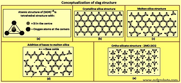
图2 渣结构概念化
添加金属氧化物,例如 CaO 和 MgO,会破坏聚合物结构。这些氧化物充当氧供体,取代四面体一角的氧原子并破坏四面体-四面体角键(图2d)。随着更多金属氧化物的加入,聚合物结构的分解继续进行,直到金属氧化物与二氧化硅的摩尔比等于 2,此时所有四面体与四面体的角键都被破坏(图 2e)。两者的摩尔比为原硅酸盐成分,2CaO-SiO2、2MgO-SiO2、CaO-MgO-SiO2。 Al2O3 以与 SiO2 类似的方式形成聚合物并从碱性氧化物中接受氧原子。接受氧的氧化物SiO2和Al2O3被称为酸性氧化物。提供氧、CaO和MgO的氧化物称为碱性氧化物。
渣碱度 – 在将多组分系统的特性与其组成联系起来以开发基于组成的指数时非常有用。制定索引的问题是如何在索引中体现系统各组成部分的重要性。酸性氧化物 (A) 和碱性氧化物 (B) 的不同性质已用于开发渣成分指数,通常称为碱度。已开发的碱度指数的例子有 (i) 过量碱 ={(CaO) + (MgO)} – {(SiO2) + (Al2O3)},(ii) 碱度 (B/A) ={(CaO) + (MgO)} / {(SiO2) + (Al2O3)},(iii) 钟形比 ={(CaO) + 0.7(MgO)} / {0.94(SiO2)+ 0.18(Al2O3)},和 (iv) 光学碱度={(CaO) + 1.11(MgO) + 0.915(SiO2) + 1.03 (Al2O3)} / {(CaO) + 1.42(MgO) + 1.91(SiO2) + 1.69(Al2O3)}。
碱度指数可分为一般类别,即 (i) 碱和酸的量之间的差异,如上述方程式 (i) 所示,(ii) 基于重量百分比的碱酸比,如方程式 (ii) 所示(iii) 基于摩尔浓度的碱酸比,如上述等式 (iii) 所示,和 (iv) 各组分的碱度及其摩尔浓度之和,如上述等式 (iv) 所示。正如前面对炉渣结构的描述所预期的那样,那些反映炉渣成分分子性质的指标,方程(iii)和方程(iv)往往是炉渣性质的更好预测指标。但是,由于公式(ii)定义的索引可能是最常用的定义。
温度影响 - [Si]、碱度和渣量 – 如图 3 所示,随着 BF 中铁水温度的升高,[Si] 的数量增加。对于给定的温度升高,[Si] 的增加量因炉而异,但趋势是所有的炉子都一样。随着[Si]的增加,(SiO2)减少,因此碱度增加,渣量减少。 [Si] 特定增加的碱度增加量是渣体积的函数。图 3a 显示了初始渣量为 200 kgs/tHM(千克每吨铁水)和 300 kgs/tHM 以及图中给出的 [Si] 和铁水温度关系的 B/A 变化。这里显示的正常趋势是渣量越大,在[Si]或铁水温度变化相同的情况下,B/A的变化越小。
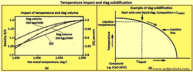
图3 温度影响与熔渣凝固
熔渣凝固 – 熔化温度的通用定义仅适用于单组分系统,例如水,其中仅存在高于熔化温度的液态水,仅存在低于熔化温度的固态水。炉渣是一个多组分系统,因此除了特定成分外,没有通用的熔化温度定义。大多数炉渣组合物在一定温度范围内同时存在固相和液相。特定成分只存在液相的最低温度称为液相线温度。
图 3b 显示了在简化相图上显示的熔渣的凝固路径。在仅存在液态熔渣的温度下从成分 Cstart 的熔渣开始。随着炉渣冷却,在图上垂直向下移动,液态炉渣的成分直到与“液相线”相交时才发生变化。与“液相线”的交点是组合物 Cstart 的液相线温度。在左侧的液相线温度下会形成非常少量的固体化合物。随着温度进一步降低到液相线温度以下,三个变化继续发生,即(i)形成更多的固体化合物,(ii)液态渣的数量减少,以及(iii)液态渣的成分发生变化,向沿着“液相线”。在所形成的化合物为 2CaO.SiO2 的示例中,由于 2CaO.SiO2 中的 CaO 含量约为 SiO2 的两倍,因此液态渣的碱度随着渣冷却而降低。
凝固路径显示了即使在液态炉渣成分与化合物的成分有很大不同的情况下,如何形成化合物。对于化合物硅酸二钙,2CaO.SiO2,CaO 与 SiO2 的重量比 =1.86。虽然从未使用 CaO 与 SiO2 接近 1.86 的炉渣成功运行任何高炉,但在运行的高炉炉渣中会形成大量硅酸二钙。形成足够的硅酸二钙会导致固体渣在冷却时分解成粉尘,称为“落渣”或“起尘”渣。分解是由硅酸二钙在 675 摄氏度发生相变时 10% 的体积膨胀引起的。据报道,避免“下落”熔渣的准则是 (CaO) 小于 0.9(SiO2) + 0.6( A2O3) + 1.75(S)。
重要的是要记住相图是基于平衡条件的。平衡条件意味着冷却速率相对于反应速率慢,例如硅酸二钙的形成。如果冷却速率非常高,如在炉渣造粒中,上述凝固路径是“绕过”的,在较小程度上是炉渣造粒。快速冷却将组合物锁定在固体玻璃相中,反应动力学太慢而无法形成化合物。
炉膛内的渣流 – 炉膛中的渣量控制对于维持稳定的熔炉运行很重要,尤其是在铁水生产率提高的情况下。高炉渣水平会导致爆破压力和腹壁工作增加,并扰乱炉料的均匀下降。控制炉渣水平的问题之一是出钢期间炉膛中的炉渣流动。在炉膛中,渣流到出铁口比铁水流到出铁口更困难。由于与熔渣相比铁水的密度更高,铁水流动具有更大的驱动力。热金属流动路径被认为主要是通过在滞留焦下方和/或周围的“无焦”区域。到出铁口的渣流路径是通过死焦焦。
图 4 显示了炉床的配置和出钢期间可能的炉床阶段顺序,这会导致出钢结束时出现虚假的干燥炉床条件。由于铁水的高密度和通向出钢口的“无焦”路径,铁水的表面被认为在整个出钢过程中在整个炉床区域保持相对平坦。炉渣表面在出钢口附近的区域比在炉缸的其他区域要低得多。当出渣速度高于通过炉缸到出铁口区域的渣流量时,出铁口区域发生渣耗尽,渣面开始向出铁口向下弯曲,如步骤 4 所示。图 4. 如图 4 的第 5 步所示,渣继续耗尽直到出钢口没有渣,并且当炉膛内仍有大量渣时,炉子看起来很干燥。 最大限度地减少渣流入的阻力炉膛最大限度地减少出钢结束时留在炉膛中的炉渣。随着炉膛焦床孔隙率的增加和炉渣粘度的降低,炉膛对渣流的阻力减小。
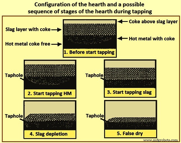
图 4 炉膛配置和出钢期间可能的炉膛阶段顺序
氧化物系统
大约 95% 的炉渣由 SiO2、CaO、MgO 和 Al2O3 组成。该四元体系中的多种组分均可满足低粘度的要求。忽略 MgO 的存在,三元氧化物体系 CaO-Al2O3-SiO2 的相图(图 5)显示了与低 Al2O3 含量的 CaO-SiO2 二元平行的低熔点区域。该区域从高 SiO2 含量延伸到 2CaO.SiO2 的饱和等温线,然后从基本恒定的 CaO 含量向高 Al2O3 含量延伸。渣中MgO含量对低熔点区的相对位置没有显着影响,只影响熔点的绝对值。
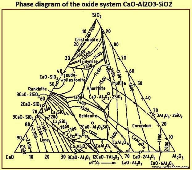
图5氧化体系CaO-Al2O3-SiO2的相图
形成高炉渣基础的氧化物系统是石灰-二氧化硅-氧化铝 (CaO-SiO2-Al2O3) 系统,由于渣中存在一定百分比的 MgO 而进行了改性。图6为CaO-Al2O3-SiO2-10 % MgO体系的相图。
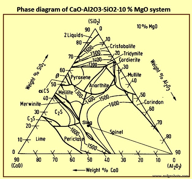
图6 CaO-Al2O3-SiO2-10 % MgO体系相图
图 7 显示了在各种操作条件下遇到的 BF 渣的组成。铁水的脱硫随着渣碱度的增加而增加,即随着 CaO 和/或 MgO 含量的增加,图 7 中的区域 1 只能用于处理低硫负荷。 Since the gangue constituents normally form a low basicity slag, region 1 largely represents the slag composition without addition of fluxes. The furnace can be operated at a relatively low temperature because of the low melting points. Region 2 is reached for low iron content burden with acid gangue constituents. This mode of operation prevails, and needs extensive desulphurization of the hot metal outside of the BF. The attainment of a basicity which results in adequate desulphurization within the furnace needs a large lime (CaO) addition which leads to a high slag volume and hence a higher coke rate. Region 3 represents the world wide preferred slag compositions for large blast furnaces. In this case, depending on the alumina content, dolomite is to be added to satisfy the needed MgO contents.
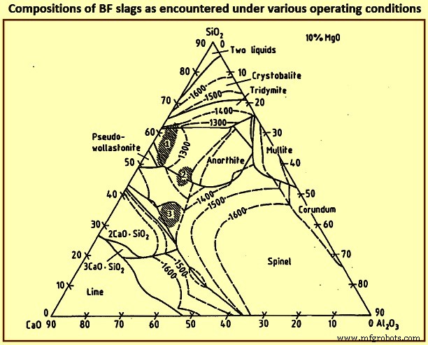
Fig 7 Compositions of BF slags as encountered under various operating conditions
Tab 1 shows the optimum components of the BF slag. Slags with higher basicities (B) as shown in Tab 1 do favour optimum softening conditions. The softening and the melting range of the gangue constituents is around 80 deg C to 130 deg C for B=0.5, and around 20 deg C to 50 deg C for B =2. Because of the higher melting temperature of the highly basic slag and of extra energy needed due to the larger quantity of the flux addition, the slag basicity is hence maintained at around 1.2.
| Tab 1 Optimum composition of BF slag | |||
| Al2O3 | CaO | MgO | SiO2 |
| % | % | % | % |
| 5 | 43 | 16 | 36 |
| 10 | 44 | 14 | 32 |
| 15 | 44 | 12.5 | 28.5 |
| 20 | 45 | 11 | 24 |
| 25 | 48 | 8 | 19 |
| 30 | 56 | 5 | 9 |
| 35 | 54 | 4 | 7 |
Slag properties
The physical and chemical properties of slags are primarily a function of the slag composition and temperature. The following describes these relationships for the purpose of developing general trends.
Liquidus temperatures – The relationships of liquidus temperature and composition for the four primary components of slag are represented on a quaternary phase diagram. Fig 8 has been generated from ternary planes of the quaternary phase diagram. Figures 8a and 8b are not phase diagrams. There are two general trends derived from these figures. The first is that the liquidus temperatures increase with increases in (Al2O3) and B/A, and the second is that the (MgO) in the range of 8 % to 14 % tends to minimize the increase in liquidus temperature caused by the increase in either (Al2O3) or B/A.
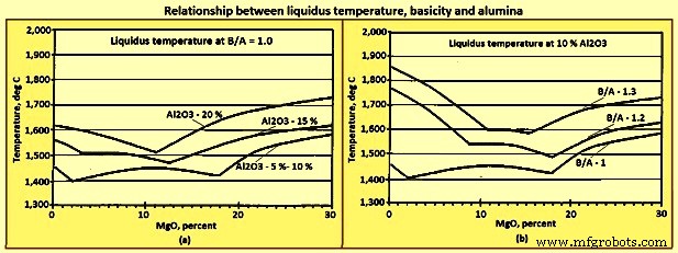
Fig 8 Relationship liquidus temperature, basicity, and alumina
Viscosity – Viscosity is a measure of the quantity of force needed to change the form of a material and is reported in unit called ‘poise’. The higher the viscosity, the more force is needed to cause a liquid to flow. For comparison purposes considering that at 20 deg C the viscosity of water is 0.01002 poise, a typical acceptable slag viscosity is around 2 to 5 poise, and the viscosity of the liquid SiO2 is of the order of 100,000 poise. The high viscosity of liquid SiO2 is caused by the polymer structure. The breakdown of the polymer structure by the basic oxides lowers the viscosity. The decrease in the viscosity of all liquid slags with increasing the B/A is shown Fig 9a. In general, the viscosity of any liquid / solid mixture increases as the quantity of suspended solids increases. The impact of temperature on slag viscosity is considerably higher at temperatures below the liquidus temperature than above the liquidus temperature as shown in Fig 9b.
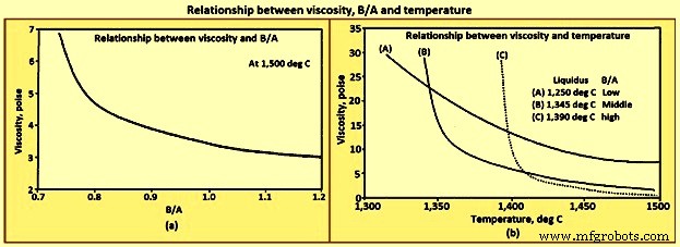
Fig 9 Relationship between viscosity, B/A and temperature
There are two general trends which are seen for the viscosity. Above the liquidus temperature, the viscosity of liquid slags decreases with increasing temperature and B/A. At temperatures below the liquidus temperature, the viscosity decreases with increasing temperature, and decreasing B/A.
Sulphur partition ratio – The BF ironmaking is a very good desulphurizing process compared to the steelmaking process because of the difference in the oxygen potential of the slags of the processes. The effect of the oxygen potential on desulphurization can be shown using equation (CaO) + [S] =(CaS) + (FeO), where the oxygen potential is indicated by the (FeO). The higher the (FeO) the more the reaction is driven to the left and the higher the [S]. Steelmaking slags with (FeO) of 15 % to 25 % are, hence, weaker desulphurizing slags than the BF hearth slags with (FeO) of less than 1 %.
Essentially all the sulphur into the BF leaves the furnace in the hot metal and slag. A relationship for the prediction of [S] can be developed based upon a mass balance of sulphur for one ton of hot metal, as per the equation (i) below, and the defined term sulphur partition as per the equation (ii) below. The prediction of [S], by equation (iii) below, is derived by the substitution of [S] from the equation (i) into equation (ii) and then solving for [S].
Equation(i) is St =[S] /100 x 1,010 + (S) /100 x Svol where 1,010 is the kgs of hot metal in a ton of hot metal including a 1 % yield loss, St is the sulphur loading which is the total weight of sulphur in kgs/tHM. Svol is the slag volume which is the weight of slag in kgs/tHM. Equation (ii) Sp =(S) /[S] where Sp is the sulphur partition ratio. Equation (iii) is [S] =St x 100 / (Sp x Svol + 1,010).
The slag Sp can be predicted based upon equation (iv) Sp =147.7 x BB + 37.7 x [Si] – 190 and equation (v) BB ={(CaO) + 0.7(MgO)} / {0.94(SiO2) + 0.18(Al2O3)}. Here BB is the basicity as defined by the bell’s ratio. It is to be noted that the coefficients in equation (iv) have been developed from regression analysis of a specific furnace. Equation (iv) and equation (v) have been used to construct Fig 10(a), and equation (iii), equation (iv), and equation (v) have been used in the construction of Fig 10 (b).
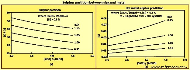
Fig 10 Sulphur partition between slag and metal
The general trends which can be derived from the above equations and figures are (i) [S] decreases with decreasing St and increasing Sp and Svol, (ii) however, Sp normally increases with B/A, (iii) CaO is a better desulphurizer than MgO, and (iv) Al2O3 has a smaller effect on Sp than SiO2.
Alkali capacity – A ‘refluxing’ or ‘recycling’ phenomena occurs in the BF due to the counter-current flow of gases versus solids / liquids, particularly for sulphur, zinc, and alkalis. The recycling of the alkali potassium (K) is shown in Fig 11a. The recycling phenomena is when an element travels down the furnace in a solid or liquid phase, reacts to form gas species in the higher temperature regions of the furnace, then travels back up the furnace as gases, where it reacts and is absorbed by the solid / liquid phases in the lower temperature region of the furnace. The recycling results in much higher internal concentrations of the recycled element than the concentration going in or out of the furnace. For example the internal loading of K can be 10 kgs/tHM, when the materials being charged contain only 2 kgs/tHM.
Alkalis have no beneficial, but many deleterious effects on the BF. Alkalis are absorbed by refractories, coke, and ore causing degradation of the refractories and coke, and ore swelling. Alkalis can also form scabs which can peel off upsetting the thermal condition of the furnace, or build up and constrict burden and gas flow. Alkalis cannot be avoided as they are contained in all coals, cokes, and to a lesser extent ores. The alkali loading is to be minimized wherever possible.
A portion of the alkalis leave the furnace in the top gas, the quantity being a function of the top temperature profile. The remaining alkalis are to be removed in the slag. The ability of slag to remove alkalis from the furnace is referred to as the alkali capacity of the slag. The relationships of alkali capacity to slag composition and temperature are shown in Fig 11b. In general the alkali capacity increases with lower B/A, and with lower temperature.
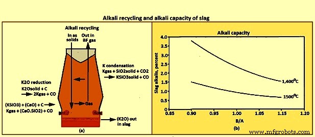
Fig 11 Alkali recycling and alkali capacity of slag
Silica activity – The [Si] produced is dependent upon the burden materials, furnace operation, and slag chemistry. The impact of the slag chemistry is shown in the equation [Si] =(SiO2) x GSiO2 / GSi x Keq / (P to the power 2)co. Here CO is carbon mono-oxide. This equation is developed from the equilibrium constant, equation Keq ={ASi x (P to the power 2)co} / { ASiO2 x Ac}, for the reaction given in equation (SiO2) + 2C =[Si] + 2COgas, the definitions of the activities of (SiO2) and [Si], equation ASiO2 =(SiO2) x GSiO2 and equation ASi =[Si] x GSi, and assuming that the activity of the carbon in the hearth is equal to one. The trend implied by Equation [Si] =(SiO2) x GSiO2 / GSi x Keq / (P to the power 2)co is that the [Si] decreases as the (SiO2) decreases.
Slag design factors
In some of the BFs, a typical slag composition which is formed from the gangue in the ore and ash of the coke is 9 % CaO, 5 % MgO, 75 % SiO2, and 10 % Al2O3. A slag of this composition has a liquidus temperature of the order of 1,600 deg C and does not flow well even above its liquidus temperature. Hence, CaO and MgO are added to the burden to ‘flux’ the gangue and ash resulting in acceptable liquidus temperatures and flow characteristics.
Basic slag design is the selection of the types and quantities of fluxes to be used with a burden and coke to produce a slag of acceptable properties. Burden and coke selections are largely driven by economic issues such as local versus imported sources and degree of beneficiation. These economic driving forces have resulted in a wide range of slag compositions throughout the world.
The general factors to be considered in designing a slag for normal operation are (i) liquidus temperature, that is, the slag is to be completely liquid in the hearth and cast house, (ii) viscosity, that is, the slag is to have a low viscosity, high fluidity, so as to drain from the hearth and down the cast house runners, (iii) sulphur capacity that is the Sp is to be sufficient to produce hot metal with sulphur contents within specifications, (iv) alkali capacity, that is, the slag alkali capacity is to be sufficient to prevent alkali build up in the furnace, (v) hot metal silicon control, that is, the effect of the slag chemistry on the [Si] is to be considered, (vi) slag volume, that is, the slag volume is to be high enough to contribute to the stability of the slag properties and hot metal quality, but not so high as to require excessive fuel or contribute to furnace instability, (vii) robust properties, that is, the slag properties are to be as insensitive to variations in normal variations in furnace operation as possible, specifically hot metal temperature, and (viii) end use, that is, the requirements of the end use of the slag is to be considered.
Slag design is to recognize that the above factors are not independent and that the design always involves a balancing of the above factors to resolve the conflicting trends (Tab 2).
| Tab 2 Normal conflicting trends | ||
| Desired parameter | Basicity | Al2O3 |
| Lower liquidus temperature | Lower | Lower |
| Lower viscosity | Higher | |
| Higher K removal | Lower | Lower |
| Lower [S] | Higher | Higher |
| Lower [Si] | Higher | Higher |
Two examples of the slag design are described below. In the first example (Tab 3) , the issue is to increase the alkali removal without increasing the [S]. The resolution of the issue is to increase the slag volume through the use of additional SiO2 in the burden, while decreasing the slag basicity.
| Tab 3 Example of designing slag for increased K2O removal | |||||
| Basicity | Slag volume | K2O | K2O removed | (S) | S removed |
| B/A | kgs/tHM | % | kgs/tHM | % | kgs/tHM |
| 1.10 | 225 | 0.47 | 1.30 | 1.82 | 5.00 |
| 1.05 | 282 | 0.55 | 1.55 | 1.77 | 5.00 |
| 1.00 | 290 | 0.63 | 1.85 | 1.72 | 5.00 |
| 0.95 | 298 | 0.71 | 2.10 | 1.68 | 5.00 |
The issue in the second example (Tab 4) is to lower the [Si] without negatively impacting the other properties of slag and furnace operation. The resolution of the issue is to decrease the (SiO2) by increasing the (Al2O3) using quartzite, a high (Al2O3) burden material, while holding the (CaO) and (MgO) constant. The change in slag chemistry results into a decrease of both [Si] and [S].
| Tab 4 Example of designing slags with lower [Si] | |||||
| Period | Unit | Base | Number 1 | Number 2 | Number 3 |
| Basicity | 1.12 | 1.13 | 1.13 | 1.12 | |
| (MgO) | % | 11.8 | 11.5 | 11.7 | 11.5 |
| (Al2O3) | % | 7.8 | 10.2 | 10.3 | 11.7 |
| [Si] | % | 0.76 | 0.53 | 0.54 | 0.49 |
| [S] | % | 0.043 | 0.031 | 0.029 | 0.026 |
Slag after the BF
The use of BF slag is driven by the economics of processing and market demand. In the place, where the processing and marketing is performed by the organization producing the slag, the markets tend to be local in nature with minimal processing. As per the present trend, independent organizations take ownership of the liquid slag at the end of the slag runner which has led to wider markets with more extensive processing. The product slag can be classified by the rate of cooling.
Air-cooled slags are those produced with low cooling rates. These are slags which are solidified in pits and frequently cooled with water sprays. The largest uses for air cooled slag are in road construction, railroad ballast, and aggregate. Air-cooled slag has also been used in the production of cement, mineral wool insulation, roofing, and glass.
Pelletized and granulated slags are those produced with high cooling rates. Pelletized slag is produced by pouring liquid slag onto a rotating drum, sometimes with water. Granulated slags are produced by either pouring the liquid slag directly into a large slag pit of water or through the use of high pressure water sprays which breaks the slag up into droplets. Rapidly cooled slags have been used for the same applications as air-cooled slags. The high glass content of rapidly cooled slags makes it particularly suitable for Portland cement production.
制造工艺