

高炉及相关辅助设备设计的重要方面
高炉及相关辅助设备设计的重要方面
高炉 (BF) 本身及其相关和辅助设备的设计(图 1)紧邻高炉的上游和下游,对于高炉的有效运行非常重要。除了熔炉本身,直接相关的设备包括 (i) 库房、(ii) 装料设备、(iii) 炉顶、(iv) 冷却系统和 (v) 铸造车间区域设备。
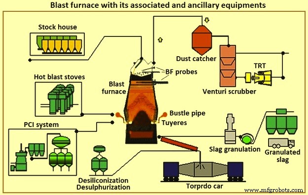
图 1 高炉及其相关和辅助设备
BF 炼铁由一个系统组成,该系统由多个协调运行的组件组成。这些组件的正确应用和操作对于支持炼铁过程是必要的。特定组件的选择取决于现有条件、物理限制、生产要求、成本、进度、可靠性和可维护性等因素。组件的相互依赖性对于系统的成功运行与它们各自的能力同样重要。每个区域或组件都有主要要求和“正常”实践。还有一些可替代的商业技术,它们具有固有的优点和缺点。
BF 将含铁矿石原料转化为液态铁(铁水)。与高炉相关的是将煤转化为焦炭的焦炉电池,以及为高炉准备铁矿石的烧结厂和球团厂。 BF 将这些准备好的原材料转化为更高价值的产品。一些高炉作业产生的铁水用于铸造厂生产铸铁件。其他操作生产低硅热金属,在炼钢车间转化为钢。一些铁水在生铁铸造机中转化为生铁。高炉的副产品是炉渣、高炉炉顶气、烟尘和滤饼。这些副产品可能会产生积极或消极的经济影响,具体取决于当地的利用可能性。
影响 BF 设计或重新设计的每一个考虑因素中的一些方面是 (i) 利润,(ii) 员工的健康和安全,(iii) 环境保护,(iv) 法规,(v)市场和下游加工,(vi) 可用的人力、建设和维护资源,(vii) 不断变化的技术和设备过时,(viii) 可用的原材料、公用事业和其他材料,以及 (ix) 等等。任何这些方面的严重限制都可能危及高炉单元(甚至钢铁厂)的生存能力,或阻止或有必要建造新的高炉。
BF 通常按大小分组。小型高炉每天生产的铁水少于 1,500 吨 (tHM/天),小型高炉的产量在 2,500 至 5,000 吨/天左右,中型高炉的产量在 6,000 至 8,000 吨/天左右tHM/天,大型 BF 每天生产大约 9,000 tHM 到 12,000 tHM。在一个综合钢厂中,需要大量和尺寸的高炉来提供钢铁生产所需的铁水。当高炉进行换衬修复或存在熔炉控制问题时,具有多个高炉的综合钢厂受到的影响较小。小高炉比大高炉更换衬里的时间短,被认为更容易操作。然而,小型高炉的铁水成本较高。综合钢铁厂需要运行最少数量的具有成本效益的熔炉。在某些情况下,会进行升级以减少运行中的熔炉数量。
BF 在其活动结束后定期更换衬里(更换衬里维修之间的时间)。过去,这涉及更换主炉的内部砖衬。近来,广泛的部件重建、更换和预防性维护同时进行。采用这种做法,与拥有更多小型高炉的工厂相比,大型高炉较少且效率更高的钢厂在高炉换衬修复期间损失的产量百分比更高。为了在高炉换衬期间实现低运营成本和最小干扰,该行业一直致力于最大限度地提高高炉的活动并缩短换衬修复的持续时间。目前综合钢厂的明显趋势是减少大型熔炉的数量,并利用无限期延长高炉活动的技术和设计。
同时,减少产品可变性变得更加重要,因此正在对自动化进行投资,以改善过程的监控和控制。高炉操作人员、维护人员、设计人员和研究人员已将现代技术和分析方法应用于高炉工艺,以更好地监测和控制工艺。结果,降低了铁水质量的标准偏差。改进的数据收集系统还为供应商和制造商提供了更多的信息。这改进了高炉和相关设备的材料选择和设计。广告系列的时长从 5 年增加到 10 年,之前已增加到 20 年左右。
BF 炼铁是一项已有 430 多年历史的技术。即便如此,使用高炉铁水仍然是综合钢厂最常用的钢铁生产方法。当今的综合钢厂工艺依靠高炉按计划提供质量一致的可预测数量的铁水。铁水供应的任何一个方面的变化都会对钢铁生产过程的其余部分产生严重影响。因此,高炉仍然是现代综合钢厂的关键工艺。
有时有人说 BF 工艺技术已达到其使用寿命。事实并非如此。对一对典型的中型高炉 23 年(1970 年至 1993 年)的运行数据的研究表明,生产率平均每年提高 3%(图 2a)。同时,燃料费率平均每年降低 1%(图 2b)。此外,通过改进设备、材料和设计,延长了 BF 换衬板(活动)之间的生产时间。因此,经通胀修正后的铁水生产总成本的改善程度甚至超过了运营数据所显示的水平。因此,尽管 BF 工艺技术已有 430 多年的历史,但它并没有消亡。它仍在以相当大的速度在各个领域取得进展。今天,BF 仍然是一门充满活力的科学,由不断改进的技术支持。
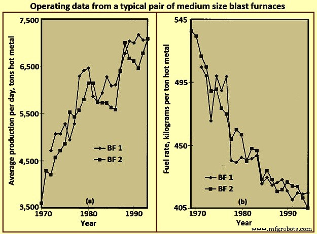
图 2 一对典型中型高炉的运行数据
BF 的布局
高炉的布局本质上是一种集成设备,以处理制造热金属所需的不同材料以及由此产生的产品和副产品。最有效的设计可以适当地适应整个过程,并且从初始资本投资和持续运营成本的角度来判断其有效性。 BF 车间布局取决于几个因素,例如 (i) 场地地形,(ii) 气候条件,(iii) 原材料输送方式,(iv) 厂内原材料加工系统和位置,(v) 下游加工系统和地点,(vi) 铁水的数量/流量要求,(vii) 铁水运输车队的类型和规模,以及 (viii) 等等。图 3 显示了一个高炉设备的简化布局。
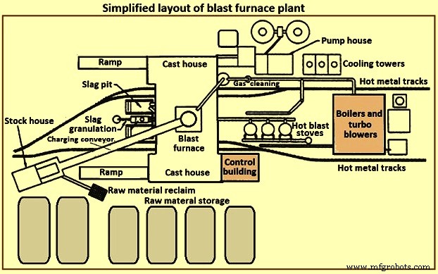
图 3 高炉厂的简化布局
一个高炉设备通常由几个部分组成。这些部分是 (i) 原材料储存、处理和回收,(ii) 仓库,(iii) 装料系统,(iv) 炉体,(v) 铸造车间,(vi) 炉渣处理和处理,(vii)
原材料储存和处理
铁矿石、烧结矿、球团矿、熔剂、煤和焦炭等原材料要么来自外部,要么在综合钢厂内生产。这些原材料需要足够的受控储存来支持高炉操作。如果发生可预测的交付中断或不可预测的中断,则需要存储容量。如果某些原材料的来源可能发生变化,则可能需要额外的存储容量。由于相似材料的物理或化学特性不同,因此需要单独的存储位置。类似材料的混合可能会导致过程控制/冶金问题。储存堆应分开,以防止不同材料的混合。将堆放在准备好的床上,以使原材料回收设备操作员能够区分主要材料和杂散材料。布置桩以最大程度地减少材料降解并防止风吹起细粉。喷水和结茧剂可用于减少灰尘被风带走。
有几种不同的技术可用于原材料的放置和回收。铺放技术包括翻车、矿桥、堆垛输送机、刮板等。回收技术包括斗轮取料机、弯曲机取料机、前端装载机、刮板机、直接从料仓或堆底等。显然,铺放和回收系统的大小应确保高炉设备所需的吞吐量。
仓库
仓库是 BF 操作员的存储单元,用于将炉料直接送入熔炉。为 BF 的每种装载材料提供存储箱。为具有不同冶金特性的类似材料(即烧结矿、球团)提供单独的料仓。如果原材料储存区的供应出现短期中断,仓库可以为各种装载材料提供足够的容量。在原材料进料损失的情况下,典型的仓库料仓吞吐量为 (i) 焦炭 – 2 小时至 8 小时,(ii) 含铁材料(矿石、烧结矿和球团) – 4 小时至 16 小时,以及助焊剂和其他杂项材料 – 8 小时至 24 小时。这些容量基于额定熔炉产量,并根据可靠性和从库存或供应商处更换它们的访问时间而有所不同。
由于气候条件和反复处理,负载材料往往会降解。物料被处理的次数越多(储存、回收、倾倒、输送溜槽、矿石桥斗等),负载中的细粉百分比就越高。 BF 工艺需要受控的渗透性,因此需要受控的负荷。过量细粉的装料,无论是通常在整个装料过程中还是集中在特定的短装料期内,都可能会破坏 BF 工艺并损坏熔炉设备。储料库提供了在装入熔炉之前清除细粉的最后合理机会。在可能的情况下,在焦炭、矿石、烧结矿和球团储存仓之后安装振动筛,以消除大部分细粉。去除的罚款被收集起来进行回收。一些高炉操作员将细粉装入炉内的特定区域,以调整局部炉子渗透性并控制炉壁上的热负荷。
仓库中经常提供水分计,以监测炉内实际装水量。此信息允许调整装料量以补偿变化的环境条件(即下雨期间焦炭水分较高)。
由于需要不同类型和不同数量的炉料来支持高炉的连续运行,因此应按特定顺序提供炉料(其本身可以经常更改以支持不同的炉子运行参数)。因此,仓库应配备可靠的设备,用于提取和喂入准确数量的特定配料,以满足特定的时间表。图 4 显示了简化的仓库设备布置。
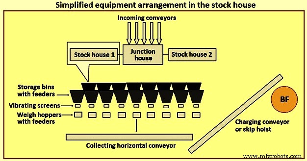
图 4 库房设备简化布置
早些时候,最常见的库存房屋类型是highline类型。这种类型的仓库直接毗邻熔炉。轨道车或桥式起重机为储料仓进料,而储料仓直接向移动秤车进料。称重车操作员手动控制料仓卸料门,将特定数量的材料送入位于称重车内的配备称重的料斗。在收集到适当类型和数量的材料后,操作员将秤车移动到“箕斗坑”上方的位置,并通过溜槽将物料倾倒到等待的箕斗车中。然后将箕斗车吊到炉顶。
高线型仓库与秤车相结合,几乎没有提供用于提供铁料(矿石、烧结矿和球团)筛选的选项。随着高炉工艺知识的增加,对炉料提出了更严格的要求。 “工程化负担”的概念如今已在业界得到广泛认可。通常认为,高线仓库的灵活性和适应性有限,无法满足这一要求。因此,高架式料场已被自动传送式料场取代,用于向高炉提供炉料。
自动化仓库通常有两种截然不同的类型。第一种是用进料器和传送带系统代替原料仓下方的称重车。为每种类型的原材料(焦炭、含铁材料、助熔剂材料和添加剂等)提供单独的输送机,其上安装有成排的储料仓,并配有振动给料机,用于将装载材料从储料仓卸到输送机上。对于含焦和含铁的物料,每条输送机的出料口都装有振动筛,对物料进行筛分,并将筛分后的物料送入称重料斗。这种类型的系统继续在料斗车之前为称重料斗进料。
第二种类型的自动化仓库是一个完全建在地面上且远离高炉的大型存储箱结构。这通常适用于使用皮带输送机而不是料车将炉料运送到炉顶的高炉。填充存储箱的方法通常是通过传送带系统。原料通过振动给料机和皮带输送机从储料仓中抽取到称重料斗中。称重料斗又通过收集输送机将物料卸到主输送机上。称重料斗被编程,以正确的顺序称量原材料到炉顶的主传送带上。
提供自动化仓库可以更有效地向仓库提供原材料,以及更有效地选择、筛选、称重和将炉料输送到熔炉。自动堆垛房可以直接靠近炉料斗车,也可以远离炉子,通过传送带装料。
仓库的自动化大大提高了生产能力,提高了运营效率,并消除了操作人员和设备造成的操作差异。然而,在实践中,现代化的自动化仓库可能非常复杂。库房本身可以通过输送机进料,然后输送机卸料到跳闸输送机上,将物料分配到各个料仓。库房内输送机和设备的布置可以有多种布置方式。将库房放置在靠近熔炉的地方经常会导致布局拥挤,并限制了未来修改的灵活性。
吊装系统
料斗一般由料斗车或传送带吊至高炉顶部。
跳过汽车吊装 – 高炉使用箕斗车是从采矿业演变而来的。 BF 箕斗车的尺寸适合熔炉吞吐量。显然,提升能力、箕斗桥设计等几个因素对箕斗尺寸都有各自的影响或约束。
通常,两个箕斗在一个共同的提升机上以相反的方式运行(以减少所需的提升功率)。箕斗在箕斗桥上的轨道上行驶,通常安装在与水平面成 60 度到 80 度的倾斜角处。整个箕斗在离开箕斗坑时缓慢加速,尽可能快地加速到达并在大部分电梯中以最大速度行驶。当它接近箕斗桥的顶部时,起重机会减慢箕斗的速度。料斗翻入炉顶装料设备时,料斗的轮子由倾卸和喇叭导轨引导。当起重箕斗到达并停在最终倾卸位置时,空箕斗(以相同速度下降)刚刚到达其行程的底部,进入箕斗坑,等待填充。跳跃式装料系统是将炉料输送到炉顶的可靠且有效的技术。然而,它对操作员来说缺乏灵活性,因为箕斗只能容纳特定数量的材料(超载会导致超载或过多的起重负载),或者如果需要少量的特定负载,则效率会降低。图5为箕斗车吊装示意图。
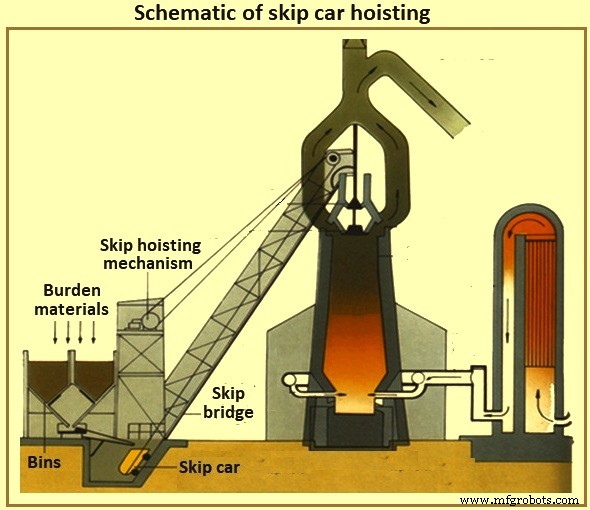
图5跳车吊装示意图
炉料输送带 – 随着仓库的输送化,起重系统的输送化也随之而来。现在,仓库远离熔炉是很常见的,一条大的传送带将物料运送到熔炉顶部。如果炉顶高约 60 米,则在水平位置倾斜 8 度安装传送带,料库距离炉膛至少 427 米。通常避免较陡的输送带倾斜,以尽量减少材料回滚。通常在传送带上的黑色金属装料结束后直接装载杂料,以便将黑色金属材料保持在适当的位置,直到它们到达炉顶。
炉顶装料系统
炉子本身在正高顶压下运行。 BF 过程产生的 BF 气体部分由一氧化碳、二氧化碳和氮气以及大量夹带的粉尘组成。由于工艺优势,高炉操作员要保持最高压力,并控制气体和粉尘(出于燃料价值和环境控制目的)。但是,操作人员要定期将炉料放入炉顶内,以补充内部工艺,同时不损失炉顶压力。
钟形顶部 – 几年来,最常见的炉顶类型是双钟顶(图 6)。随着炉料到达炉顶(通过箕斗或传送带),它落入接收料斗和小钟形料斗。小钟(直径约 2.6 米、高 1.4 米的锥形铸钢铸件,用于每天 5,000 吨高炉的高炉)降低并允许负载落入大钟形料斗中。小钟被提升并密封在小钟漏斗上的固定座上。根据大钟形料斗的体积,额外的负载负载由小钟形按顺序进入大钟形料斗。在整个过程中,大钟一直保持关闭,密封熔炉。收集到正确数量的负载后,大钟(直径约 5.5 米、高约 3.5 米的锥形钢铸件,每天 5,000 吨高炉)降低并允许负载从钟形滑入炉顶适当。卸料后,大钟升起并密封在大钟形料斗的下侧。图6为钟罩式BF顶装系统。
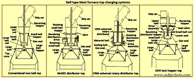
图 6 钟罩式高炉炉顶装料系统
显然,这种炉子的炉料分配控制受到大钟罩上炉料的均匀程度(跳过倾倒导致炉料在这种炉子上的不均匀放置)和炉料的下降曲线的限制。特定的配料(即焦炭或铁料)从大钟上滑落。进一步地,两个钟形顶容易失去大小钟形密封以及大钟形杆和小钟形管之间的密封性。钟形泄漏是由于负载材料在钟形密封表面上滑动造成的磨损造成的。棒填料泄漏是由于炉内的细粉磨损或炉料倒入接收料斗后收集在大钟形棒上的结果。
为了尽量减少大钟形密封表面的磨损,将取自炉内的 BF 气体引入钟形罩之间以平衡空间(减少大钟形密封表面的压差)。这种气体在打开小钟罩之前被释放到大气中,以允许引入更多的负载。下面给出了一些可用于改善两种钟形顶部系统限制的选项。
McKEE 经销商 – McKEE 分配器(图 6)多年来一直是可用于双钟型顶部的主要负载分配改进。然而,它正在迅速被其他技术所取代。它的设计结合了小钟形和小钟形料斗在料斗车卸料时一起旋转的能力。负载均匀分布在小钟形料斗中,从而提高了大钟形负载的均匀放置。这种顶盖容易发生大小钟形磨损,进而丧失密封效果。
CRM 通用旋转分配器顶部 – CRM(Centre Recherches Metallurgiques – Belgium)通用旋转分配器(图 6)的开发是为了消除小钟形密封效果的损失。安装了两个钟(一个密封钟和一个材料钟)来代替普通的小钟。料斗上装有回转料斗。密封罩位于料罩下方并密封固定座。箕斗卸料时,料斗和闭合料钟转动,使料斗均匀填满。填充完成后,料斗旋转停止。当需要倾倒到大钟上时,旋转料斗、料钟和密封钟下降。密封罩降低到固定座下方。在下降过程的中途,料斗下降停止,料钟和密封钟继续下降,直到它们到达停止位置。由于料斗和料斗之间的间隙打开,料斗均匀地排放到大钟形料斗中。由于负载离开间隙,它不会与密封阀座面接触,从而保持顶部密封能力。这种顶盖可以保持0.2兆帕的内压。
CRM 顶部提高了两个钟形顶部的密封能力和使用寿命。然而,与 McKEE 分配器相比,它并没有显着改善炉料分布,也没有消除大钟形密封表面的脆弱性。
GHH 锁料斗顶部 – GHH 锁定料斗顶部(图 6)是对双钟顶部的修改。它减少了对大钟罩的依赖来保持气密封。为每个翻斗位置添加带有单独密封阀的锁定料斗,为顶部密封提供了额外的能力。大钟罩可以在其密封表面上没有压差的情况下运行(即炉顶压力等于大钟罩料斗压力)。操作如下。
箕斗通过接收料斗和打开的密封阀将装载物倾倒到锁定料斗中。物料放在旋转的小钟罩上,并均匀地填满小钟罩上方的旋转分配料斗。在旋转过程中,锁定料斗和旋转的小钟形料斗之间的密封打开。箕斗卸料完成后,关闭闸式料斗和小钟形料斗之间的密封阀和密封。引入平衡气体并将锁料斗加压至炉顶压力。然后降低小钟形以将负载引入大钟形料斗。小钟关闭,来自锁料斗的压力释放到大气中。另一侧(即另一个箕斗倾卸位置)的密封阀打开。锁式料斗和小钟形料斗之间的密封打开。小铃铛和料斗开始旋转。顶部现在可以接受来自其他跳跃的负担。
这种类型的顶部提高了两个钟形顶部的密封能力和寿命。然而,与 McKEE 或 CRM 顶部相比,闭锁式料斗顶部并未提供显着的炉料分布改进。虽然不再需要大钟罩来执行密封功能,但小钟罩的密封效果寿命仍然很关键。
可动装甲 – 为改善钟形顶部的负载分布而采取的主要步骤是开发可移动装甲(图 7)。可调节的偏转器安装在炉的喉部区域,以在炉料从大钟上滑下后偏转。可移动装甲根据卸出的具体炉料和操作员希望将炉料放置在炉内的位置进行调整。
几家制造商提供不同类型的活动装甲。单个装甲段可以在炉内均匀(同时和等量地)移动,以将炉料放置在环形模式中。其他类型的活动装甲可提供对装甲板的单独控制,以实现非圆形分布模式。
与可移动装甲相关的一些缺点是(i)大部分机械和磨损部件位于炉顶锥的恶劣环境中,(ii)需要一些内部工作体积损失以提供可移动装甲和设计料线之间的间隙水平(尽管考虑到熔炉工作量,熔炉的这个区域不能被归类为粗略的生产区,并且 (iii) 将炉料偏转到熔炉中心的能力有限,特别是当料线水平已经很高时。轧制弹丸的特性经常否定可动装甲的有限位移。
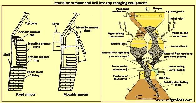
图 7 Stockline 装甲和无铃顶部充电设备
无铃顶部充电系统 – 1970 年代初期,卢森堡的 Paul Wurth S.A. 开发了无钟顶 (BLT) 充电系统(图 7)。这种炉顶与钟罩式炉顶完全不同。炉子可以按照炉子操作员需要的任何模式放置在炉子内。环形环、螺旋、分段和点放置是常见的模式,可通过位于炉顶锥体的配料分配槽的同步或独立倾斜和旋转来实现。
炉顶密封在整个炉子运行期间保持不变。维护活动简单且持续时间短。通常,BLT 包括一个接收溜槽或料斗(从箕斗或传送带接收物料)、一个带有上下密封阀的锁定料斗、一个物料流控制门、一个主溜槽驱动齿轮箱(水或气体-用于溜槽旋转和倾斜的冷却装置)和配料分配溜槽。 BLT主要分为三种类型,即(i)平行料斗,(ii)中央进料和(iii)紧凑型。
通常,平行型包含两个锁定料斗(料斗已安装在某些熔炉上,用于吞吐量和备用目的;一个“偏心”料斗类型已安装用于间隙受限的应用)。自 1980 年代初以来,一些高炉选择了“中央进料”单锁料斗类型,因为它改进了炉料分离和炉料分配控制,从而改善了炉子操作。
已经为中小型熔炉开发了一种“紧凑型”BLT 顶部,以允许将 BLT(及其优势)引入由于成本或物理限制而无法使用其他大型 BLT 的熔炉。中央进料型 BLT 操作的步骤是 (i) 料从箕斗或传送带通过接收溜槽或料斗通过打开的密封阀进入锁定料斗,(ii) 在料仓被接收后料斗,关闭上密封阀并引入平衡气体以将闭锁料斗加压至炉压,(iii) 下密封阀打开,(iv) 当料门设置为预选开口以适应特定的卸料物料,(v) 料料通过主传动齿轮箱的进料口垂直下降并落到料料分配槽上,(vi) 料料分配槽将料料引导至所需炉内的点,(vii) 当闭锁料斗完全排放(由称重传感器和/或声学监测器监控)时,下密封阀关闭,(viii) 打开安全阀以排出闭锁料斗气氛re (or through an energy recovery unit), and (ix) the upper seal valve opens and the sequence is repeated.
The advantages of BLT over other top charging systems include higher top pressure capability (i.e. 0.25 MPa), fuel savings, increased production, more stable operation, reduced maintenance in terms of cost and time, increased furnace campaign life, and improved furnace operational control when employing high coal injection rates at the tuyeres.
Gimbal system of charging – The purpose of the Gimbal system of charging is to facilitate controlled distribution of charge material into the BF via a Gimbal type oscillating chute through a holding hopper and variable material gate opening such that the pressurized charging system above can operate independently of the distribution system. It utilizes a conical distribution chute, supported by rings in a Gimbal arrangement, producing independent and combined tilting of the chute axis. The Gimbal distributor, as part of the overall BF top charging system, offers a fully integrated charging solution, generating considerable improvement in BF operation and maintenance cost. The Gimbal system utilizes a conical distribution chute, supported by rings in a Gimbal arrangement, producing independent, and combined tilting of the chute axis.
The Gimbal top incorporates a full complimentary range of furnace top distribution equipment including distribution rockers, upper seal valves, hoppers, lower seal valves, material flow gates and goggle valve assemblies, all discharging through hydraulically driven distribution chutes. The tilting chute is driven by two hydraulic cylinders, mounted 90 degree apart. This type of suspension and drive arrangement results not in a rotation of the tilting chute, but in a circular path by superposition of both tilting motions. Independent or combined operation of the cylinders allows the chute axis to be directed to any angle, or even along any path. Motion is supplied by two hydraulic cylinders, each operating through a shaft, connecting rod, and universal joint in order to drive the Gimbal rings. Through the movement of the hydraulic cylinders, the distribution chute allows precise material distribution with potential for an infinite number of charging patterns at varying speeds. These include ring, spiral, centre, spot, segment or sector charging, providing complete control of material charging into the furnace.
The whole distributor assembly is enclosed in a gas tight housing, which is mounted directly onto the top flange of the BF top cone. The housing contains a fixed inlet chute and a tilting distribution chute supported by rings in a Gimbal arrangement allowing independent and combined tilting of the chute axis. The assembly is made from a combination of stainless and carbon steel material with the fixed inlet chute and tilting chute body lined with ceramic material to give superior wear protection. A closed-circuit water cooling system supplies cooling water through the main shafts, Gimbal bearings, and universal joint bearings in order to cool the moving elements of the Gimbal distribution system.
The key features of the Gimbal design are (i) simple, rugged design, using levers driven by the hydraulic cylinders, (ii) drive cylinders are mounted outside pressure envelope, hence not subject to hot and dusty service conditions, (iii) Gimbal ring arrangement gives simple tilting motion in two planes, which when superimposed gives 360 degrees distribution, and (iv) wear on the tilting chute is equalized around its circumference giving a long extended operational life.
The BF Gimbal top is an automated, computer-controlled pressurized charging system designed to (i) receive charges of ore, coke, and miscellaneous materials in the holding hopper, independently of the distribution system below, (ii) release those discharges, as needed, to a dynamic distribution chute located below the holding hopper, and (iii) distribute material in prescribed patterns to the furnace stock-line in accordance with a predetermined charging matrix. Control of the Gimbal distribution chute is fully integrated into the overall furnace charging software. The system provides a high level of accuracy and control for the Gimbal movements and hence the positioning of the distribution chute. Gimbal material distributor is shown in Fig 8.
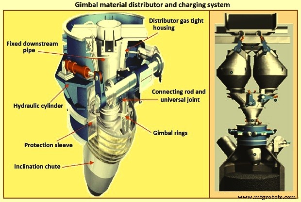
Fig 8 Gimbal material distributor and charging system
Furnace proper
The furnace proper is the main reactor vessel of the BF ironmaking process. Its internal lines are designed to support the internal process. Its external lines are designed to provide the necessary systems to contain, maintain, monitor, support, and adjust the internal process.
The BF process is a counter flow process. The process comprises of (i) burden at ambient conditions is placed in the furnace top onto the column of burden within the furnace, (ii) as the burden descends with the burden column, it is heated, chemically modified, and finally melted, (iii) further chemical modifications occur with the molten material, (iv) the molten products are extracted near the bottom, (v) melting of the burden material and extraction result in the descent of the burden column and the need for replenishment of the burden at the top, (vi) hot blast air is introduced through tuyeres near the bottom, (vii) BF gases are generated in front of the tuyeres and ascend through the burden and chemically modify the descending burden as well as themselves get chemically modified and cooled, (viii) BF gas (and dust) is extracted near the top of the furnace, and (ix) heat is extracted from the vessel in all directions (primarily through the lining cooling system) and along with the BF gas, liquid iron and liquid slag. Fig 9 shows cross section and types of BF.
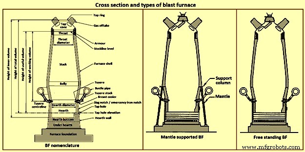
Fig 9 Cross section and types of blast furnace
Furnace type – Furnaces are constructed to be mantle supported or free standing. Mantle supported BFs characteristically have a ring girder (mantle) located at the bottom of the lower stack of the furnace. The mantle is supported in turn by columns which are on the main furnace foundation. The hearth, tuyere breast, and bosh are also supported by the foundation. Furnaces with mantle support column tend to have restricted access and reduced flexibility for improvements in the mantle, bosh, and tuyere breast areas.
Since thermal expansion is a major consideration in furnace shell design, the mantle style of furnace provides an interesting design consideration. The mantle support columns are relatively cool. The mantle tends to maintain a constant height, throughout the furnace campaign with respect to the furnace foundation. Thermal expansion of the stack due to process heat is considered to be based at the ‘fixed’ mantle (i.e. the top of the furnace raises with respect to the mantle). The effective height of the bosh, tuyere breast, and hearth wall shells (supported on the furnace foundation) increases due to the thermal expansion of the shell caused by the process heat. The lower portion of the furnace lifts upwards towards the fixed mantle. Hence, the provision of an expansion joint of some type is needed at the bosh / mantle connection or somewhere appropriately located in the lower portion of the furnace.
Free standing furnaces have been developed to eliminate the column and permit the installation of major equipment and furnace cooling improvements. This furnace type has a thicker shell for structural support. Installation and maintenance of a reliable cooling and lining system is necessary in order to sustain the structural longevity of the shell.
Two variations of the free standing furnace have been used. One type provides for a separate structural support tower to carry the furnace off-gas system and charging / hoisting system load. The other type (while it does employ a separate support tower for shell replacement purposes during relines) uses the furnace proper to support the off-gas system and charging / hoisting system loads. Special consideration to the furnace shell design is to be made regardless of the furnace type. The furnace vessel is subjected to internal pressures from the blast and gas, burden, liquid iron and slag. Dead and live load during all operating, maintenance, and reline stages are to be considered as well.
Furnace zones – The major zones of the furnace proper are (i) top cone, (ii) throat, (iii) stack, (iv) mantle / belly, (v) bosh, (vi) tuyere breast, (vii) hearth walls, (viii) hearth bottom, (ix) foundation.
Top cone – The top cone or dome is the uppermost part of the furnace proper. It supports the furnace top charging equipment, and the BF top gas collection system. Stock rods (stockline recorders or gauges) are normally placed here to monitor the upper level of the burden in the furnace. These devices are the units which provide the permissive or indication signals to charge the next scheduled burden input to the furnace. Typically, they are weights lowered by special winches, or microwave units. Some furnaces incorporate radio-active isotope emitters and detectors mounted in the furnace throat to monitor the burden level. Infrared camera can be installed in the top cone to monitor the BF top gas temperature distribution as it escapes the furnace burden stockline.
The top cone is the coolest zone of the furnace proper but can be exposed to extremely high temperatures if burden ‘slips’ (rapid, uncontrolled burden descent after a period of unusual lack of descent). The newly charged burden falls through this zone and the BF top gas is carried away from this section.
Throat – Steel wear plates or armour are installed in this zone. Here, abrasion of the furnace lining from the charged burden is the prime cause of deterioration. Furnace operators work to maintain the upper level of the burden (the stockline) in this region. Movable armour can be installed in this area in order to deflect the burden falling from a large bell. With the installation of the BLT, wear of the stockline area can be greatly reduced. Some BF users select to eliminate the armour plates and use an abrasion resistant refractory lining instead.
Stack – The stack (sometimes called shaft or the ‘in-wall’) is the zone between the mantle or belly on a free standing furnace and the stockline area. Smooth, uniform lines (the process ‘working surface’) of the stack are essential for uniform and predictable burden descent, BF gas ascent, and stable process control throughout the furnace campaign. Process considerations dictate a larger diameter at the base of the stack than at the top. Typical stack angles are in the range of around 85 degrees from the horizontal.
Mantle / belly – The mantle or belly area provides the transition between the expanded stack and bosh sections. Maintenance of the effectiveness of the cooling / lining system is particularly important for the mantle type furnace in order to protect the mantle structure. Thermal protection is important for the free standing furnace type as well. However, the free standing design is less complicated and more accessible in this area.
Bosh – The bosh area lies between the tuyere breast and the mantle / belly of the furnace. The bosh diameter increases from bottom to top. The inclination of the bosh permits the efficient ascent of the process gases and has been found to be necessary in order to provide the needed zone service life (the process gases are extremely hot and internal chemical attack conditions are severe). Typical bosh angles are in the range of around 80 degrees from the horizontal. Boshes are of two basic types, namely (i) banded and (ii) sealed. They can be cooled by different techniques.
Banded boshes are found in older mantle supported furnaces (they cannot be applied to free standing furnaces). A number of steel bands are placed in incrementally increasing diameters (smallest at the bottom of the bosh and largest at the top) and are tied together with connecting strips. Gap between the bands permits the introduction of copper cooling plates. Ceramic brick lining is to be used as air infiltration results in oxidation of carbon based linings. Gas leakage through the banded bosh can be high. This type is not suitable for BFs with high blast pressure / high top pressure. Banded boshes provide adequate flexibility to eliminate the requirement for a shell expansion joint in the lower portion of the furnace.
Sealed boshes, using continuous steel shell plate instead of separate bands, are employed to permit the use of improved cooling / lining systems, higher furnace operating pressures, and the free standing furnace type. Sealed boshes retain valuable gases with the furnace, hence improving the metallurgical process. As well, the seal bosh, since it precludes air entry into the lining, supports the use of carbon based refractories.
Tuyere breast – Hot blast air is introduced to the furnace through tuyeres (water-cooled copper units) located within the tuyere breast. The number of tuyeres needed depends upon the size (production capacity) of the furnace. The tuyere breast diameter, tuyere spacing, and number of tuyeres are influenced by the expected raceway zone size in front of each tuyere.
Tuyere stocks (Fig 10) convey the hot blast air from the bustle pipe to the tuyeres. The tuyeres are supported by tuyere coolers (water-cooled copper units) which are in turn supported by steel tuyere cooler holders (either welded or bolted to the furnace shell). Special consideration are to be made in the tuyere breast shell and lining design in order to maintain effective sealing of the different components in order to prevent escape and loss of the furnace gases.
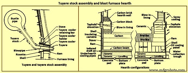
Fig 10 Tuyere stock assembly and blast furnace hearth
Hearth – The hearth (Fig 10) is the crucible of the furnace. Here, hot metal and liquid slag are collected and held until the furnace is tapped. The hearth wall is penetrated by tap holes (frequently called iron notches) for the removal of the collected hot metal and liquid slag. The number of tap holes is dependent upon the size of the furnace, hot metal, and liquid slag handling requirements, physical and capital constraints etc.
Several furnaces are equipped with a slag or cinder notch (normally one per furnace, although some furnaces can have two). The slag notch opening elevation is normally sufficiently higher than the iron notch elevation. In earlier days, when slag volumes were high, the slag was flushed from the slag notch periodically. This simplified the iron / slag separation process in the cast house. More commonly now, however, the slag notch is retained solely for initial furnace set-up procedures or for emergency use in case of iron notch or other furnace operating problems.
Hearth bottom – The hearth bottom supports the hearth walls and is flooded by the iron within the furnace. As the campaign progresses, the hearth bottom lining wears away to a fixed equilibrium point. The remaining refractory contains the process and with sufficient cooling or inherent insulation value protects the furnace pad and foundation.
Cooling system
The application of specific cooling techniques to individual furnace zones is dependent upon several factors such as campaign life expectancy, furnace operational philosophy, burden types, refractories, cost constraints, physical constraints, available cooling media, and preferences etc. Different cooling techniques can be provided for different zones to assist the lining to resist the specific zone deterioration factors. Normally, the provision of adequate cooling capacity is necessary in each of the applicable furnace zones if the lining system located there is to survive. Where the thermal, chemical, and to some extent the abrasive conditions of the process are extreme, sufficient cooling is to be provided to maintain the necessary uniform interior lines of the furnace and to protect the furnace shell.
Typically, the top cone and throat areas of the furnace are not cooled. The hearth bottom can be ‘actively’ cooled by under hearth cooling (air, water, or oil media) or ‘passively’ cooled by heat conduction though the hearth bottom lining to the hearth wall. The basic cooling options for the balance of the furnace are (i) no cooling (typically the upper portion of the stack is not cooled in several furnaces, (ii) shower or spray cooling, (iii) jacket or channel cooling, (iv) plate cooling, and (v) stave cooling.
Shower or spray cooling – Water is directed by sprays or by overflow troughs and descends in a film over the shell plate. Effective spray nozzle design, numbers and positioning are important for proper coverage and to minimize rebound. Proper deflector plate design is necessary to ensure efficient cooling water distribution and to minimize splashing. Shower cooling is frequently employed in the bosh and hearth wall areas. Spray cooling is normally applied for emergency or back-up cooling, primarily in the stack area. Exterior shell plate corrosion and organic fouling are common problems which can disrupt water flow or insulate the shell from the cooling effect of the surface applied cooling. Water treatment is an important consideration to retain effective cooling.
Jacket or channel cooling – Fabricated cooling chambers or indeed structural steel channels or angles are welded directly to the outside of the shell plate. Water flows at low velocity though the cooling elements in order to cool the shell and the lining. Jacket or channel cooling is frequently applied to the hearth walls, tuyere breast, and bosh areas. Scale build-up on the furnace shell and debris collection in the bottoms of the external cooling elements can compromise the cooling effectiveness. Hence periodic cleaning of the cooling elements is necessary.
The critical area of concern in the cooling schemes mentioned so far is the necessity for the shell plate to act as a cooling element. If extreme heat loads are acting upon the inside face of the shell, then there exist an extremely high thermal gradient across the shell. This effect results in high thermally induced shell stresses and eventual cracking. The cracks start from the inside of the furnace and propagate to the outside. The cracks remain invisible (other than a ‘hot spot’) until they fully penetrate the shell plate. Through cracking of the shell plate results in the leak of the BF gas, exposed shell carburization, and disruption of the cooling effect (particularly spray or shower cooling). Shell cracking into a sealed cooling jacket or channel is difficult to locate and can result in long furnace outage time for repair. Entry of water into the furnace (frequently when the furnace is off-line and internal furnace gas pressure cannot prevent entry of cooling water though shell cracks) can have detrimental effect upon the furnace lining. Water in the furnace can be potentially dangerous due to explosion risk (steam or hydrogen). Since shower and jacket cooling rely on the shell plate to conduct the process heat to the cooling media, the plate and stave cooling are configured to isolate the shell from process.
Plate and cigar cooling – Installation of cooling elements though the shell of the furnace (Fig 11) has been a major furnace design improvement resulting in effective cooling of the furnace lining and protection of the shell plate. Cooling is provided along the length of the cooling element penetration into the lining. The inserted elements provide positive mechanical support for the refractory lining. Typical cooling plate manufacture is cast high conductivity copper. Single or multiple passes of cooling water can be incorporated. Cooling boxes with larger vertical section have been produced from cast steel, iron, or copper.
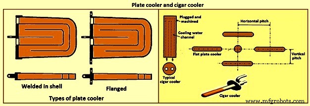
Fig 11 Plate cooler and cigar cooler
Cigar type (cylindrical) coolers (Fig 11) of steel and /or copper have also been successfully used. The philosophy of dense plate cooling (i.e. vertical pitch of 350 mm to 400 mm centre-to- centre, and horizontal pitch of 600 mm (centre-to-centre) has improved the cooling effect and increased lining life.
Copper cooling plates have traditionally been anchored in the shell plate with retainer bars or bolted connections to permit ready replacement if plate leakage occurs. More recently, plates have been designed with steel sections at the rear of the plate for welding directly to the steel shell. While sometimes taking longer to replace, this type provides a positive seal against BF gas leakage. Plate coolers are typically installed in areas above where the liquid iron collects in the furnace. Hence the mid-point of the tuyere breast, right up to the underside of the throat armour is the range of application.
Stave cooling – Cast iron cooling elements (Shannon plates or staves) have been used for several years in the bosh and hearth wall areas. These castings have cored cooling passages of large cross-section. While their service life have been not remarkable in the bosh, multiple campaigns have been normal for the hearth wall. These staves frequently suffered from low flow rates of marginal quality cooling water (scaling and debris deposition / build-up) and sometimes casting porosity. Water leaks into the hearth wall can be a considerable problem.
In the 1950s, the then USSR developed a new type of stave cooler (Fig 12) and ‘natural evaporative stave cooling’. For this design, castings were of gray cast iron containing steel pipes for water passes. The pipes were coated prior to casting to prevent carburization of the cooling pipe and metallurgical contact with the stave body material. The staves were installed in horizontal rows with the furnace and the cooling pipes projected through the shell. Vertical column of staves were formed by the inter-connection of the projecting pipes from one stave up to the corresponding stave in the next row. Staves can be applied to all the walls in the zones below the armour. Staves in the hearth wall and tuyere breast are supplied with smooth faces. Staves in the bosh, mantle / belly and stack normally have rib recesses for the installation of refractory.
Evolution of the stave cooler design has been dramatic. Staves in the higher heat load areas are now typically cast from ductile iron for improved thermal conductivity and crack resistance. While early stave design used castable refractory (installed after stave installation within the furnace), ribs now normally incorporate refractory bricks, either cast in place (with the stave body at the foundry) or slid and mortared in place prior to installation in the furnace. Fig 12 shows stave cooler and generations of stave development.
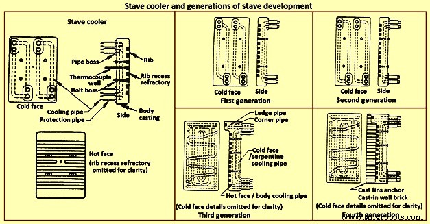
Fig 12 Stave cooler and generations of stave development
Staves are normally expected to retain a refractory lining in front for some time. After loss (expected) of the lining the staves are designed to resist the abrasive effects of descending burden and ascending dirty gas. As well, they are to absorb the expected process heat load and resist thermal load cycling and shock. Four generations of staves (Fig 12) are normally recognized in the industry.
First generation staves are no longer normally used. These staves have four cooling body circuits (with long radius bends which do not effectively cool the stave comers. These staves are made of gray iron castings with castable rib refractory. Second generation staves have four cooling body circuits with short radius bends for improved comer cooling. These staves are made of ductile iron castings with cast-in or glued-in rib bricks. Third generation staves have two-layer body cooling incorporating four or six cooling body circuits (stave hot face) and one or two serpentine cold face circuits (stave cold face) for additional or back-up cooling in the event of hot face circuit loss. These staves have additional edge cooling (top and bottom). The more frequent use of these staves is as cooled ledges to support a refractory lining. These staves have cast-in or mortared-in rib bricks. Fourth generation staves have two-layer cooling (similar to third generation). These staves have cooled ledges and cast-in wall brick lining eliminating the need for a manually placed interior brick lining.
Staves incorporating hot face ledges are more effective in retaining a brick lining than the smoother rib faced bricks. However, once the brick lining disappears, the ledges are very exposed within the furnace. The ledges disrupt burden descent and gas ascent. Exposed ledges tend to fail quickly. They are frequently serviced by cooling water separate from the main stave cooling circuit(s). In this way leaking ledge circuits can be more easily located or isolated. Some stave manufacturers are now providing separate ledge castings so that ledge cracking and loss does not damage the parent staves. As well, there is some present change in philosophy to abandon the application of ledges entirely.
Variations of the basic stave generation types are common. For example, staves of fourth generation type utilizing a refractory castable for the wall ling have been employed successfully. Alternatively, brick linings have been anchored to the stave bodies. Such approaches can be used to substitute for brick support ledges.
A ‘fifth’ generation of staves design has been the developed. It is the copper stave (Fig 13). The development of copper staves was carried out both in Japan and Germany for use in the region of bosh, belly, and lower stack to cope with high heat loads and large fluctuations of temperatures. While Japan has gone for cast copper staves, German copper staves are rolled copper plates having close outer tolerarnces and with drilling done for cooling passages. Drilled and plugged copper staves are typically designed for four water pipes in a straight line at the top and four water pipes in a stright line at the bottom. Materials for internal pipe coils include monel, copper, or steel. Unlike cast iron staves, copper staves are intended to be bonded to the cooling pipe.
The development of the cast-in copper stave has considered the following aspects. As per the first aspect, for the prevention of deformation, appropriate design of the stave length and bolt constrained points is important. The first aspect is that the use of the cast-in steel pipe copper stave with its own design is beneficial for effectively reducing the risk of deformation. Fig 13 shows the constrained points of a rolled copper stave and the cast-in steel pipe copper stave. A rolled copper stave is constrained to the shell by mounting bolts and pins. To prevent the weld at the base of a rising pipe from being damaged by stresses, rising piping is connected to the shell by an expansion joint. Due to this structure, the upper and lower ends of the staves are freely displaced, causing the staves to be easily deformed. The large thermal load which is repeatedly applied to the copper stave in the course of the fluctuation in the BF operations etc., causes plastic strain to be gradually accumulated, and results in large deformation. There are cases in which the deformation at the upper end has reached 50 mm or more and a weld has been broken, under the condition of an overly long stave, an in-appropriate bolt position, or high heat load exceeding the design condition.
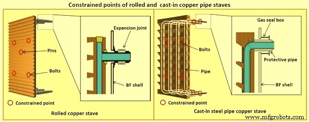
Fig 13 Constrained points of rolled and the cast-in pipe copper stave
Presently, the most popular type of copper stave is the rolled copper stave, the manufacturing process of which involves drilling holes on a copper plate. The water channel ends of these staves are plug-welded. The cast-in steel pipe copper stave, which has been developed, is made by casting bent steel pipes into the copper, a completely different manufacturing process from that of the conventional rolled copper stave. This unique manufacturing method has enabled achieving high energy efficiency and long life of BFs, which cannot be achieved using the rolled copper stave.
Natural evaporative stave cooling (NEVC) is a technique where boiler quality water is introduced into the bottom row of staves and flows by natural mean up the vertical cooling circuits. As the process heat conducts through the stave and cooling pipe into the water, the water in turn heats up. As the water warms, it expands. Since cooler water is being introduced below, the warm water tends to move upwards. At some point in the vertical cooling circuit, the water is at the boiling point. As the water changes its phase to steam, due to the latent heat of vapourization, additional heat is absorbed (driving the phase change). After boiling begins, two-phase flow (water and steam mixture) ascends the cooling pipes to the top of the furnace. Normally located on the furnace top platform are steam separator drums used to extract and vent the steam to atmosphere. Make-up water is introduced to the drum (to replace the discharged steam). The water is piped back by gravity to the furnace bottom and is fed once more to the staves. This cooling technique is very efficient and has low operating costs. There is no pumping equipment. The improvements in this system has been to boost the flow of the cooling water with recirculating pumps (forced evaporative cooling, FEVC) in order to ensure uniform cooling water flow and to cool the recirculating water (forced cold water cooling – FCWC). Both of these approaches have resulted in improved stave and lining life.
Staves provide an excellent protection for the shell plate throughout their service life (which is extended while the interior brick lining remains in place). Stave application has been implemented in all areas of the furnace from hearth wall up to and including the upper stack.
One drawback for conversion of an existing plate cooled furnace to stave cooling can be the cost of a new shell. However, if the existing shell is already in distress and is to be replaced in any event, the conversion cost is not a major factor.
Cast house
The cast house (Fig 14) is the area or areas at the BF where equipment is placed to safely extract the hot metal and liquid slag from the furnace, separate them, and direct them to the appropriate handling equipment or facilities. The hot metal and liquid slag are removed from the furnace through the tap hole. Only infrequently today slag is flushed from the slag notch. The equipment for tap hole is to be reliable and need minimum maintenance. Furnaces typically tap eight times to eleven times per day.
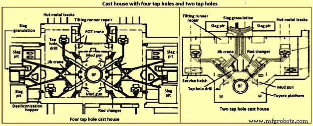
Fig 14 Cast house with four tap holes and two tap holes
Mud gun – The mud gun is used to close the tap hole after tapping is complete. A quantity of the tap hole mass is pushed by the mud gun to fill the worn hole and to maintain a quantity of the tap hole mass (the mushroom) within the hearth. The mud gun is normally held in place on the tap hole until the tap hole mass cures and the tap hole is securely plugged. A hydraulic mud gun uses hydraulic power to swing, hold, and push the tap hole mass. Typical injection pressure of tap hole mass is of the order of 20 MPa to 25 MPa, permitting it to push viscous mass into the furnace operating at high pressures. The hydraulic gun is held against the furnace with the equivalent of 15 tons to 35 tons of force. This type of mud gun can be swung into place in one motion.
An electro-mechanical gun has three separate electric drives for unit swing, barrel positioning, and ramming. Hence several separate motions are needed for accurate positioning of the mud gun at the tap hole. Tap hole mass injection pressure is in the range of only 5 MPa to 8 MPa. The electro-mechanical mud gun is latched to the furnace to keep it in place during plugging.
Tap hole drill – Tap hole drill is used to bore a hole though the tap hole clay into the hearth of the furnace. A drill unit is swung into place hydraulically and held hydraulically in the working position. A pneumatic motor feeds the hammer drill unit (with an attached drill rod and bit) into the hole. Compressed air is fed down the centre of the drill rod and the drill bit to cool the bit and blowout the removed tap hole mass. When the tap hole drill rod has penetrated into the hearth, the drill rod is retracted and the drill swings clear of the hot metal stream.
Soaking bar technique – The application of the soaking bar practice has improved the tapping process. When the tap hole mass is still pliable after plugging, a steel bar is driven into the tap hole by the tap hole drill. While the bar sits in place during the time between casts, it heats up by conduction from the hearth hot metal. This permits curing of the tap hole mass along its entire length (as opposed to curing with the furnace and setting at the outside near the furnace cooling elements). The cured tap hole mass is more resistant to erosion during tapping, hence improving tap flow rate control. Less tap hole mass is needed to replug the hole. When the tap hole is to be opened, a clamping device and a back hammering device on the tap hole drill extract the rod. The timing for tap hole opening can be more easily controlled (predicted) than by conventional drilling. This feature is important for smooth furnace operation and for scheduling of hot metal delivery to downstream facilities.
Same side tap hole equipment – Mud gun and drills have normally been installed on opposite sides of the tap hole. Design development has permitted installation of these equipments on one side of the tap hole. The drill swings over the mud gun or vice versa. This type of installation facilitates improved access for tap hole and trough maintenance and the improved application of trough and tap hole area flue collection.
With the advent of tuyere access platforms to facilitate tuyere and tuyere stock inspection and replacement, the headroom available for the tap hole equipment has diminished. However, same side tap hole equipment installations can be achieved with low headroom (for example 2.2 metres).
Trough and runner system – Typical hot metal and slag tapping rates are in the range of 4 to 6 tons per minute and 3 to 5 tons per minute, respectively. The trough and runner systems are to be designed to properly separate the iron and slag and to convey them away from the furnace for flow rates within the normal flow rate range and for unusual peak flow rates.
The hot metal trough (Fig 15) is a refractory lined tundish located in the cast house floor and designed to collect iron and slag after discharge from the furnace. The hot metal flows down the trough, under a skimmer and over a dam into the hot metal runner system. The hot metal level in the trough is dictated by the dam. Proper dam design submerges the lowest portion of the skimmer in the hot metal pool. The slag, being lighter than the hot metal, floats down the trough on top of the hot metal pool. Since it cannot sink into the hot metal and through the skimmer opening, it pools on top of the hot metal until sufficient volume collects to overflow a slag dam and run down the slag runner. At the end of the tapping, the slag runner dam height is lowered to drain off most of the slag. The residual hot metal is retained in the trough to prevent oxidation and thermal shock of the trough refractory lining.
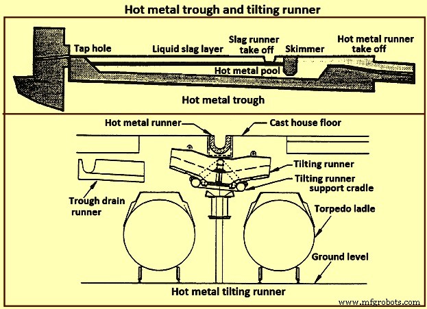
Fig 15 Hot metal trough and tilting runner
When maintenance of the trough lining is needed, the hot metal pool can be dumped by removing the hot metal dam, or by opening a trough drain gate, or by drilling into the side of the trough (at its lowest point) with a drain drill. The trough bottom is normally designed with a 2 % (minimum) slope for effective draining. Trough cross-section and length design are important for effective iron and slag flow pattern, retention, and separation. A good trough design results in hot metal yield improvements. Effective trough lining and cooling techniques are important for lining life, hot metal temperature, and cast house structural steel and concrete heat protection considerations. Troughs traditionally were contained in steel boxes ‘buried in sand’ in the cast house floor system. Improved trough design incorporates forced or natural air convection or water-cooling.
Cast house practice needs the runners to be as short as possible. This minimizes temperature loss of hot metal and reduces runner maintenance and flue generation. Shorter runners can also result in reduced capital expenditure for cast house building installation or modification. Since the runners are to slope away from the furnace, the cast house floor normally follows the same slope as the runners.
Slag runners are normally designed with a 7 % (minimum) slope. Slag can be directed to (i) slag pots for railway or mobile equipment haulage to a remote site for dumping, (ii) slag pits adjacent to the furnace for air cooling and water quenching prior to excavation by mobile equipment, and (iii) granulation facilities adjacent to the furnace for conversion of the liquid slag to granulated slag. Granulation units are provided with systems to eliminate flue emissions associated with environmental issues.
Hot metal runners are normally designed with a 3 % (minimum) slope. Hot metal is normally directed to hot metal transfer ladles (torpedo cars / open top ladles) for movement to the steel melting shop or pig casting machines. While normal practice used is to have one iron runner system with diverter gates directing the hot metal to different pouring positions, each with a ladle. Application of the tilting runner practice has been beneficial. A tilting runner is normally with an electrical motor-driven actuator (with a manual hand wheel back-up), and is tilted at around 5 degrees to divert the hot metal. A pool of hot metal is held in the tilting runner to minimize splashing and refractory wear. When one hot metal ladle has been filled, the runner is tilted to the opposite side to fill the other ladle. If needed, a locomotive removes the filled ladle and spots an empty ladle in its place. This operation can be done without plugging the furnace. When the tapping is finished, the tilting runner is tilted an additional 5 degrees to dump its pool of hot metal into the ladle.
Modern cast house design includes flat floors, where the runner is fully covered and is fitted flush with the floor. This allows safer and easier use of mobile vehicles in the cast house area. The use of radio controlled equipment and other devices have helped to reform cast house work, and these, along with effective emission control systems, have improved working conditions. As the BF hearth diameter is increased, there is a resulting need to increase the size of the cast-house. Large BF are normally designed with four tap holes (Fig 14). With a four top-hole configuration, the cast-house arrangement needs to provide sufficient space for movement around the floor itself. There is no design issues associated with this requirement as long as there is the necessary space provided in the site plan. Increasing the size of the cast-house in terms of floor plan does not represent a radical change in design philosophy which can pose a challenge the furnace designer. An efficient and strictly controlled tapping is necessary for ensuring a stable operation and high productivity of the BF.
Emission control
Fume collection requirements and applications appear to vary considerably around the globe. BFs presently have full, partial, or even no cast house fume collection system. Exhaust fan and bag house capacity of the order of 9,000 cubic meter per minute (cum/min) to 11,500 cum/min (depending upon operation and design practices) is typical for full flue capture of a two tap hole cast house installation (for trough runners and tilting runners).
Proper design and application of flue collection runner covers can facilitate cast house access (i.e. flat floor configuration using steel slabs or plates) for personnel and mobile equipment crossover. Runner covers can also reduce hot metal temperature loss and improve runner refractory longevity.
Some furnaces use flame suppression which eliminates the oxygen in the air directly over the trough and iron runners. Products of combustion prevent oxidation of the hot metal surface reducing visible particulate and flues.
Other aspects of BF design
It is necessary that complete study of every element in the process chain, from raw materials delivery to hot metal consumption is made to ensure that there are no ‘bottle necks’ in the system which can prevent the furnace from meeting the goals of its installation. While designing the BF, thought process is to be used to develop the furnace design and some alternatives are to be considered before freezing the design. During the designing of the furnace, those furnace equipments are to be selected which best meet the needs of the furnace operation.
The furnace design is to ensure (i) the furnace is capable of meeting the operational goals of production, productivity (tons per day per cubic metre of working volume), specific consumptions (kilograms per ton of hot metal), and product quality in cost effective manner, (ii) the furnace has the flexibility to accept and absorb the changes in the quality of the raw materials, and (iii) the furnace is capable of achieving the desired campaign life both with respect to time and the total production.
Financial justification is the over-riding consideration for the design. For this purpose, the economic study is to be very extensive. Further, the furnace design is to include latest technological developments so that the furnace does not become technologically outdated during its entire campaign.
The working volume of the furnace is the internal volume of the furnace calculated between the tuyeres and the stock line. Hearth productivity of the furnace is rated in tons per day per cubic metre of active hearth volume. Active hearth volume is the internal volume of the furnace calculated between the tuyeres and the tap hole. Active hearth volume is a measure of the holding capacity of the furnace for the liquids produced in the working volume (above the tuyeres). Hence, the tons per day per cubic metre of active hearth volume is a measure of the specific capacity (through-put per unit volume) of the hearth of the BF.
The design of the hearth is very important since it has a strong effect on the furnace operation. The furnace operation gets affected since the hearth liquid levels change rapidly which cause variations in gas flow pattern, gas utilization, and blast pressure. Also, because of these rapid changes in liquid level, there can be jamming / burning of the tuyeres which affect the blowing of the furnace.
The furnace hearth volume also determines the controls the operator is to exercise during furnace operation. For a very good hearth liquid level control, the high through-put furnace need around 90 % time spent in tapping. To make this time of tapping possible, cast floor is to be designed properly.
The furnace lining and cooling system needs special attention so that it does not pose any problem during the entire campaign of the BF. The selection of refractories, cooling elements, and internal furnace geometry is very important in this respect. Copper staves in this respect are expensive but they are very economical in comparison to the alternatives. Carbon lining of the hearth is very important for the long life of the hearth. The refractory lining thickness of the stack has implication on the furnace working volume.
The production needed normally determines the size of the BF. However, for the sizing of the BF, the raw materials, the product chemistry, and even operating philosophy are important. While the furnace size has implication on the capital cost, the productivity improvement has implication on the operating cost. The specific productivity of the furnace is to be determined for the determination of the size of the BF needed to produce the required quantity of hot metal. From the wide range of possible operating rates, the working volume of the furnace is to be calculated. Productivity and hence the furnace size is also to be based on the fuel rate. The fuel rate is dependent on the quality of raw materials, hot blast parameters, hot metal quality, and the operating philosophy.
The size is the most important factor for the determination of the BF productivity. However, there are other factors which also influence the BF productivity. The most important of these factors include (i) hot blast temperature and pressure, (ii) high top pressure, (iii) oxygen enrichment of the air blast, (iv) injection of auxiliary fuel at the tuyere, (v) prepared burden (sinter, pellets etc.), (vi) Fe content of the ferrous burden, (vii) ash in coke, (viii) quality of the coke, (ix) moisture content of the burden, (x) direct charging of fluxes (lime stone, dolomite etc.) in the BF, (xi) content of fines in the burden, (xii) quality of hot metal to be produced, (xiii) burden distribution control in the furnace, and (xiv) level of automation and control in the furnace.
The availability of furnace equipment, provision of stand-by equipment, and the maintenance philosophy are important factors which have high influence on the annual production from the BF. Further, incorporation of safe and healthy working practices during the operation of BF in the design of the BF is important which has a high influence on the furnace productions. In this regards, safety interlocks are to be provided at all the places where there exist a chance of unsafe operating practices to take place.
制造工艺