

钢铁材料在拉伸试验中的行为
钢铁材料在拉伸试验中的行为
钢铁的机械性能通常通过拉伸试验来评估。测试技术非常标准化,可以用最少的设备经济地进行。由于钢铁材料用于结构应用,因此它们的拉伸性能应符合相关规范和标准的要求。规范和标准中的这些要求是最低强度和延展性水平。因此,从拉伸测试中获得的信息通常未被充分利用。然而,直接检查影响拉伸测试结果的许多冶金相互作用可以显着提高测试数据的实用性。检查这些相互作用,以及与冶金/材料/应用变量(如热处理、表面光洁度、测试环境、应力状态和预期的热机械暴露)的相关性,可以显着提高使用效率和质量。钢铁材料在工程中的应用。
对钢铁材料进行拉伸测试的原因有很多。拉伸性能通常包含在材料规格中以确保质量,并且通常用于预测这些材料在除单轴拉伸之外的不同形式的加载期间的行为。拉伸试验的结果通常用于选择这些工程用材料。它为开发机械性能数据提供了一种相对简单且廉价的技术,用于在工程应用中选择、鉴定和利用这些材料。这些数据通常用于确定这些材料对特定应用的适用性,和/或为与其他替代材料进行比较提供依据。
钢铁材料的弹性模量取决于试样的拉伸速率(应变速率)。发生特定数量的塑性应变时的屈服强度 (YS) 或应力也取决于测试应变率。材料成分、晶粒尺寸、预先变形、测试温度和热处理也会影响测量的 YS。通常,增加 YS 的因素会降低拉伸延展性,因为这些因素也会阻碍塑性变形。然而,这一趋势的一个显着例外是随着晶粒尺寸减小时延展性的增加,延展性增加。
几种结构材料在拉伸试验中因应变而失效时,会因延展性过程而断裂。断裂面由微孔的聚结或组合形成。这些微孔通常在塑性变形过程中成核,并且在塑性变形过程变得高度局部化后开始聚结。应变速率、测试温度和微观结构会影响聚结过程,并且在选定的条件下(例如降低温度),断裂会经历从韧性到脆性的转变。这种转变会限制这些材料的实用性,而这在强度测量中可能不会注意到。
钢铁材料的弹性行为
钢铁结构的设计通常使建筑材料在正常使用条件下承受弹性载荷。这些载荷在材料中产生弹性或可逆应变。高大的钢结构建筑在强风中的摇摆就是弹性应变很容易看到的一个例子。汽车轴的弯曲和桥梁随着车辆通过的拉伸是不太明显的弹性应变的例子。应变的大小取决于支撑载荷的材料的弹性模量。虽然弹性模量一般不通过拉伸试验来确定,但拉伸行为可以用来说明弹性性能在钢铁材料选择和使用中的重要性。
铁 (Fe) (207 GPa) 的杨氏模量几乎是铜 (Cu) (117 GPa) 的 2 倍,是铝 (Al) (69 GPa) 的 3 倍左右。由于其较高的杨氏模量值,当部件承受等效载荷时,由 Fe 制成的部件比由 Cu 或 Al 制成的类似部件的挠曲更小。例如,在拉伸试验过程中,直径为 12.8 mm 的 Fe、Cu 和 Al 拉伸棒的弹性拉伸应变加载到 455 kg,Fe 为 0.00016 mm/mm,Cu 为 0.00029 mm/mm,Cu 为 0.0005 mm/mm铝。钢抵抗弹性变形的能力是因为它的“刚度”特性,杨氏模量 (E) 是衡量这种特性的一种方式。需要非常刚性结构的工程建设将由非常大的组件或具有高弹性模量值的材料完成。由于Fe的弹性模量高于许多其他材料,因此钢铁材料常用于需要高刚度的应用中。
定义杨氏模量 (E) 的方程“S =Ee”是基于拉伸应变 (e) 与施加的应力 (S) 成线性比例的观察结果。这种线性关系很好地解释了钢铁材料在大多数实际情况下的行为。然而,当这些材料受到循环或振动载荷时,即使稍微偏离真正的线性弹性行为也可能变得很重要。衡量偏离线弹性的一种方法是材料的非弹性响应。
抗弹性
非弹性是一个完全可逆的变形过程,它与时间有关。时间依赖性是由于在施加负载期间缺乏立即的原子运动。时间相关的变形过程有许多机制,包括杂质原子的扩散运动。这种扩散运动可以简单地是原子跳跃到附近的晶格位置,由于施加了载荷而变得有利。
钢铁材料是一种 Fe-C(碳)合金,其拉伸载荷在材料中产生弹性应变,其体心立方 (bcc) 结构变形为体心四方 (bct)。 C,在固溶体中,在 Fe 晶格中产生类似的变形。拉伸载荷引起的变形和碳溶解引起的变形有一个基本区别。在拉伸测试期间材料晶格的平均变形是各向异性的,这意味着结构的每个单元格在拉伸载荷的方向上被拉长,并且由于泊松比,材料也在横向方向上收缩。相比之下,由 C 解引起的平均晶格畸变是各向同性的,即使每个单独的 C 原子都会产生局部各向异性畸变。
固溶在 Fe 中的碳原子位于间隙位置,如图 1 示意性所示。由于溶解的 C 原子对于间隙位置来说太大,位置 X 的 C 原子将 Fe 原子 A 和 B 推开,使晶胞在 x 方向伸长。类似地,位置 Y 的 C 原子将 Fe 原子 B 和 C 推开并导致 y 方向的伸长,而位置 Z 的 C 原子导致 z 方向的伸长。在任何给定的无应力 Fe 或 α 晶粒内,C 原子随机分布在 X、Y 和 Z 位点。因此,虽然每个晶胞在一个特定方向上发生变形,但未受应力晶粒的整体变形基本上是各向同性的,或在所有方向上都相等。
拉伸应力的应用会导致特定的间隙有利位点。如果拉伸应力平行于 x 方向,则 X 型位点会扩大并成为 C 原子的有利位点。如果应力在 y 方向,则 Y 型位点会受到青睐,而当应力在 z 方向时,Z 型位点会受到青睐。在拉伸试验期间,C 原子迁移或扩散到因施加拉伸载荷而变得有利的位置。这种迁移取决于时间和温度,并且可能是非弹性变形的原因。突然施加的拉伸载荷会使材料晶格以如此高的速率发生弹性应变,以至于在施加载荷时不会发生C向有利位置的迁移。
然而,如果材料保持在负载下,由于间隙 C 倾向于将 Fe 原子推向施加应力的方向,因此向有利位置的时间依赖性迁移会产生额外的晶格应变。这种附加应变是材料中的非弹性应变。同样,如果负载突然释放,弹性应变会立即恢复,而非弹性应变的恢复需要时间,因为间隙 C 原子从先前有利的位置重新定位以在材料晶格中形成均匀分布。弹性应变和非弹性应变的时间依赖性示意图如图1所示。
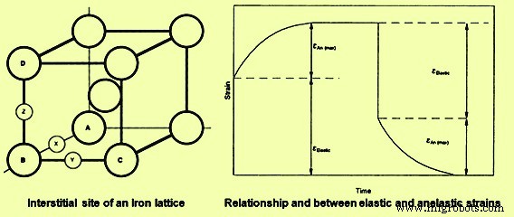
图1弹性和非弹性应变的铁晶格和时间依赖性
在拉伸试验期间确定的弹性应变和非弹性应变的组合导致杨氏模量取决于载荷率(或应变率),并且可以在承受循环或振动载荷的材料中产生阻尼或内摩擦。当测试样品加载并保持在固定位移时,非弹性应变是拉伸测试期间应力松弛的原因之一。这种应力松弛通常被称为“弹性后效应”,其结果是由于时间相关的负载下降,因为随着原子移动到有利位置并发生非弹性变形,维持固定位移所需的负载会减少。这种弹性后效证明了时间或加载速率对测试结果的重要性。
伴随向测试样品施加拉伸载荷的总可逆应变是弹性应变和非弹性应变的总和。载荷的快速施加导致非弹性应变接近零(测试时间不足以满足非弹性应变),因此加载过程中的总应变等于真实弹性应变。相同载荷的非常缓慢的应用允许非弹性应变伴随加载过程,因此该测试中的总可逆应变超过快速加载期间的可逆应变。在低应变率测试中测得的杨氏模量值低于在高应变率测试中测得的值,因此测得的弹性模量与应变率有关。杨氏模量的低值称为“松弛模量”,在高应变率下测得的模量称为“非松弛模量”。
阻尼能力
拉伸测试和循环加载通常在完全松弛行为所需的应变或加载速率与完全非松弛行为所需的应变或加载速率之间进行。因此,在加载或卸载时,应力-应变曲线的初始或短时间部分会产生非松弛行为,而曲线的后期、较长时间部分会产生更松弛的行为。从非松弛行为到松弛行为的转变会在应力-应变曲线中产生加载-卸载滞后。这种滞后表示加载-卸载循环期间的能量损失。能量损失的量与滞后的大小成正比。这种可归因于材料晶格内的非弹性效应的能量损失被称为“内摩擦”。内摩擦对钢铁材料吸收振动能量的能力起着关键作用。这种吸收会导致材料的温度在装载-卸载循环期间升高。材料对内摩擦敏感性的一种衡量指标是阻尼能力。
由于非弹性和内摩擦取决于时间和温度,因此材料的阻尼能力既取决于温度又取决于应变率。内部摩擦和阻尼在材料对振动的响应中起着关键作用。在加载-卸载循环期间引起显着内部摩擦的条件下测试的钢铁材料会经历大量能量损失,并且据说具有高阻尼能力。这些材料可用于吸收振动。例如灰口铸铁,它具有非常高的阻尼能力,并经常用于仪器和设备的底座,这些底座将与区域振动隔离开来。轧机机架、车床和压力机等通常使用铸铁底座,以减少机器振动传递到地板和周围区域。然而,高阻尼能力并不总是一种有用的材料质量。
钢铁材料的回弹性、阻尼、应力松弛和弹性模量也取决于材料的微观结构以及测试条件。这些特性通常不是通过拉伸测试技术确定的。然而,这些特性以及机器参数会影响应力-应变曲线的形状。
比例限制
在拉伸应力-应变关系中产生曲率所需的表观应力是比例极限 (PL)。 PL 定义为应变与应力保持方向成比例的最大应力。偏离比例可归因于非弹性和/或塑性变形的开始。在拉伸测试期间检测这些现象发生的能力取决于测量应力和应变的准确性。 PL 的测量值随着测量精度的提高而降低。由于 PL 的测量值取决于测试精度,因此 PL 通常不作为材料的拉伸性能报告。此外,PL 的价值在工程应用材料的选择、鉴定和使用方面几乎没有用处。材料的 YS 是一个更具可重复性和实用性的应力。
材料的屈服和塑性的开始
钢铁材料的 YS 可以定义为材料在应力和应变之间的比例上表现出特定偏差的应力。非弹性效应可能会导致非常小的比例偏差,但这种与线性行为的偏差是完全可逆的,并不代表显着塑性(不可逆)变形或屈服的开始。 YS 的理论值由方程 YS =E/2p 计算,其中 E 是弹性模量,p 是 Pi (3.14159) 的值。理论上,除非施加的应力占弹性模量的很大一部分,否则不会发生屈服。在钢铁材料的情况下,这种对屈服的估计通常超过了对测得的 YS 的至少 150 倍的预测。理论和实际 YS 之间的差异是由于位错的运动造成的。位错是晶格中的缺陷,这些缺陷的运动是塑性变形的主要机制。改变材料YS的技术依赖于缺陷相互作用来改变位错运动的难易度。
位错迁移率取决于合金含量、冷加工程度、夹杂物和第二相颗粒的尺寸、形状和分布,以及材料的晶粒尺寸。强度随着合金含量的增加而增加,因为合金(或杂质)原子与位错相互作用并阻止随后的运动。因此,这种强化是点缺陷与线缺陷相互作用的结果。
冷加工是提高钢铁材料强度的有效技术。这种强化机制是有效的,因为材料中的位错数量随着冷加工百分比的增加而增加。这些额外的位错限制了其他位错的继续运动。由于线缺陷与晶格中的其他线缺陷相互作用,冷加工是强化的一个例子。轧制、冲压、锻造、拉深、型锻甚至挤压均可用于提供必要的冷加工。
晶粒和相界也阻止位错运动。因此,YS 随着晶界数量的增加和/或随着结构中第二相百分比的增加而增加。晶粒尺寸的减小会增加每单位体积的晶界数量,从而增加材料晶格中区域缺陷的密度。由于面缺陷和线缺陷之间的相互作用限制了位错迁移率,YS随着晶粒尺寸的减小和第二相粒子数量的增加而增加。
由于强化机制不同,钢铁材料的 YS 范围很广。 YS 的范围取决于晶粒尺寸、冷加工百分比、第二相颗粒的分布以及其他相对容易量化的微观结构参数。微观结构参数的值取决于材料的热机械历史。因此,了解重要的冶金变量几乎是智能解释 YS 数据以及设计和利用由这些材料制成的结构和部件的必要条件。
YS 最常见的定义是产生 0.002 mm/mm 塑性应变所需的应力。这种应变代表了一个容易测量的比例偏差,产生这种偏差所需的应力是 0.2% 的偏移量 YS。在达到 0.2% 的线性行为偏差之前,需要大量的位错运动。因此,在标准拉伸试验期间,0.2% 的偏移屈服强度几乎与试验机变量、夹持效应和可逆非线性应变(如非弹性)无关。由于这种独立性,0.2% 的偏移屈服强度是一种可再现的属性,用于描述钢铁材料的机械性能。尽管如此,重要的是要知道 YS 的大小或任何其他拉伸特性取决于测试材料的缺陷结构。因此,如果要将 YS 用作有意义的设计参数,则需要了解材料的热机械历史。
屈服点
一些钢铁材料,主要是在室温下测试的低碳钢,位错运动的开始是突然的,而不是一个相对渐进的过程。这种突然出现的屈服使得用 0.2% 偏移方法表示屈服是不切实际的。由于突然屈服,低碳钢的应力-应变曲线有一个屈服点(YP),低碳钢的YS用较低的屈服应力来描述。 YP 是由于溶质(溶解)原子和溶剂(主体)晶格中的位错的相互作用而产生的。低碳钢中的溶质-位错相互作用涉及 C 迁移到位错并与位错相互作用。由于相互作用导致位错附近的溶质浓度高,因此据说由于C偏析到位错中而形成了YP点。
位错周围的许多间隙位点被扩大,因此是低能量或有利于溶质原子占据的位点。当这些扩大的位点被占据时,高浓度的溶质或气氛与位错有关。在低碳钢中,溶质偏析在位错处产生富C气氛。位错的运动受到限制,因为这种运动需要将位错与 C 气氛分离。一旦发生分离,继续位错运动所需的应力就会降低,并且在拉伸试验中,会达到较低的 YS。该屈服过程涉及测试样品的局部区域中的位错运动。由于位错运动是塑性变形,因此位错移动的区域代表材料中的变形区域或带。这些局部的、变形的条带被称为 Lu¨ders 条带。一旦开始,额外的应变会导致 Lu¨ders 带在整个测试样品的标距长度上传播。
这种传播发生在钢的较低 YS 的恒定应力下。当整个量规截面已经屈服时,由于位错与其他位错的相互作用,应力-应变曲线开始上升,并开始应变硬化。由于突然软化和局部应变对加工技术的影响,YP 和 Lu¨ders 带的存在很重要。例如,突然的局部屈服会导致材料的急速流动。在拉伸操作中不希望出现不平稳的材料流动,因为拉伸设备上的负载变化迅速,导致大量能量释放,这些能量将被加工设备吸收。此外,在冲压过程中,局部 Lu¨ders 应变会在材料中产生拉伸痕迹。这些妊娠纹被称为“拉伸应变”,在冲压表面上很明显。这会破坏表面的外观并降低组件的实用性。如果冲压没有 YP 的材料,由于应变硬化过程将变形均匀地分布在整个材料中,因此会形成光滑的表面。
粒度对产量的影响
结构应用中使用的钢铁材料是多晶的。这些材料通常包含大量的微观晶体或晶粒。由于晶粒的三维形状相当复杂,晶粒的尺寸难以精确定义。如果假设晶粒是球形的,则可以使用晶粒直径 (d) 来指定尺寸。为了更精确地指定晶粒尺寸,它通常包括平均晶粒截距(I)和晶界表面与晶粒体积的比值(Sv)。这两个参数可以通过定量金相技术确定。
但是,由于历史原因,参数d是用来描述晶粒尺寸对钢铁材料YS影响的最常用的量度。这种影响通常通过 Hall-Petch 关系量化,其中 YS 通过经验方程与晶粒尺寸相关。
晶界作为位错运动的障碍,导致位错在边界后面堆积。这种位错的堆积将应力集中在堆积的尖端,当应力足够时,可以在相邻晶粒中形成额外的位错。位错堆积尖端的应力大小取决于堆积中位错的数量。由于较大的晶粒体积,堆积中包含的位错数量随着晶粒尺寸的增加而增加。堆积中位错数量的这种差异使得新位错在大晶粒材料中比在纯度相当的细晶粒材料中更容易成核,并且这种位错成核难易程度的差异直接外推到 YS 的差异.
冷加工和应变硬化的影响
钢铁材料在高于再结晶温度的塑性变形是热加工,而这些材料在低于再结晶温度的塑性变形是冷加工。这些材料在再结晶温度以上的拉伸试验中没有表现出明显的应变硬化,拉伸YS成为材料可以有效承受的最大应力。这些材料的应力-应变曲线表明,引起持续塑性变形所需的应力随着拉伸应变的增加而增加。
持续变形所需的应力通常称为特定拉伸应变下的流动应力。随应变增加而增加的流动应力是通过冷加工提高材料强度的基础。晶粒尺寸对材料强度的影响在整个冷加工过程中保持不变。强度的晶粒尺寸依赖性在整个应变硬化过程中保持不变的事实确立了这些材料中各种强化机制之间相互作用的可能性。例如,冷加工通过点缺陷和位错之间的相互作用导致强度增加,这些效应是合金化效应的叠加。
此外,强度不是受冷加工过程影响的唯一拉伸性能。延展性随着冷加工的增加而降低,如果冷加工过度,钢筋会在冷加工过程中开裂和断裂。冷加工对强度和延展性的总体影响是强度的增加和延展性的降低导致应力-应变曲线下的面积减小。这很重要,因为这个面积代表了钢筋断裂所需的功或能量,而拉伸试验的结果表明,这个能量随着冷加工百分比的增加而降低。
冷加工,无论是通过轧制、拉伸、冲压还是锻造,都会改变微观结构。最终的晶粒形状由加工过程中金属流动的方向决定。冷轧样品中的晶粒被拉长并变平,从而从半球形晶粒变为煎饼状晶粒。拉杆工艺产生针状颗粒。除了晶粒形状的变化外,晶粒内部还会因冷加工操作而变形。高位错密度带(变形带)发展,孪晶界弯曲,晶界变得粗糙和扭曲。由于变形引起的显微组织变化是各向异性的,因此锻钢材料的拉伸性能往往是各向异性的。冷加工导致的应变硬化显微组织和伴随的机械性能可以通过退火显着改变。通过加热到较高温度引入的微观结构变化取决于退火的时间和温度。这种温度依赖性的结果是因为需要原子运动才能使退火有效。
抗拉强度
应变硬化能力是将钢铁材料与其他工程材料区分开来的机械行为的正常特征之一。并非所有金属材料都显示出这种特性。例如,铬 (Cr) 非常脆,在拉伸试验中断裂,没有应变硬化的迹象。脆性材料的应力-应变曲线与陶瓷材料的相似。断裂发生在发生显着塑性变形之前。这种脆性材料没有真正的YS,断裂应力是材料所能承受的最大应力。但钢铁材料在断裂前发生塑性变形,材料所能承受的最大应力明显高于YS。这个最大应力(基于原始尺寸)就是材料的极限或抗拉强度(TS)。
YS 和 TS 之间的余量为结构中的钢铁材料提供了操作安全系数。除了这个安全边际,TS 的实际值几乎没有什么实际用途。结构承受复杂使用载荷的能力与TS关系不大,结构设计应以屈服为基础。 TS 易于测量并且经常被报告,因为它是应力-应变曲线上的最大应力。工程规范有时会规定材料要满足特定的 TS 要求。
从历史上看,设计计算中使用了基于经验的减少量以避免屈服的 TS。随着应力-应变曲线测量精度的提高,TS 的利用率降低,到 1940 年代,一些设计规范基于屈服。有一个大型经验数据库将 TS 与硬度、疲劳强度 (FS)、应力断裂和机械性能相关联。这些相关性、历史规范要求以及脆性材料结构设计要基于 TS 的事实为继续使用 TS 作为设计标准提供了技术基础。
钢铁材料的冷加工和其他强化机制不会像增加 YS 一样快速增加 TS。因此,强化过程通常伴随着承受塑性应变能力的降低。这种减少会降低材料在断裂前吸收能量的能力,并且在许多情况下,这对于成功利用这些材料很重要。分析这些材料的拉伸行为可以深入了解材料的能量吸收能力。
韧性
吸收能量而不破裂的能力是由于材料的韧性。在大多数情况下,钢铁材料的断裂始于预先存在的缺陷。这些缺陷可以小到足以成为微观结构的元素,或者当稍大时,可以是材料中的宏观裂纹,或者在极端情况下,是结构中视觉上可观察到的不连续性。坚韧的钢材可以通过屈服和塑性变形等过程抵抗缺陷的传播。这种变形的最大值发生在缺陷尖端附近。由于断裂涉及拉伸应力和塑性变形或应变,因此应力-应变曲线可用于估计材料韧性。然而,有专门的测试旨在测量材料的韧性。这些测试中的大多数是使用预先破裂的样品进行的,包括冲击力学和断裂力学。基于拉伸行为的韧性计算是估计值,不用于设计。
应力-应变曲线下的面积是拉伸试验期间材料吸收能量的量度。该区域是对材料韧性的粗略估计。 Since the plastic strain associated with tensile deformation of iron and steel materials is typically several orders of magnitude greater than the accompanying elastic strain, plasticity or dislocation motion is very important to the development of toughness. This is demonstrated by the stress-strain curves for a brittle, a semi-brittle, and a ductile material. Brittle fracture takes place with little or no plastic strain, and thus the area (A) under the stress-strain curve is given by the equation A =0.5 Se. Estimation of the fracture energy from the typical tensile properties of mild steel test sample with a YS of 205 MPa, TS of 415 MPa, and strain to fracture value of 0.3, gives 1.12 J/ cu mm of gauge section of the test sample.
The ratio of the energy for ductile fracture to the energy for brittle fracture is 900. This ratio increases with increasing strain to fracture and with increasing strain hardening. The area and energy relationship is only approximate. The utility of such toughness estimates is the ease with which testing can be done and the insight that the estimates provide into the importance of plasticity to the prevention of fracture. Further, a plastic strain of only 0.01 % can have a remarkable effect on the ability of the material to absorb energy without fracturing.
Toughness is a very important property for many structural applications. Crane arms, ship hulls, axles, gears, and couplings are all required to absorb energy during service. The ability to withstand earthquake loadings, system overpressures, and even minor accidents also need material toughness. Increasing the strength of iron and steel materials usually reduces ductility and, in many cases, reduces toughness. Thus, increasing the strength of the material can increase the likelihood of service-induced failure when material toughness is important for satisfactory service.
This is seen by comparing the areas under the two stress-strain curves in Fig 2. The cross-hatched areas in Fig 2 show another tensile property which is the modulus of resilience. Modulus of resilience can be measured from tensile stress-strain curves. The ability of iron and steel materials to absorb energy through elastic process is the resilience of the material. The modulus of resilience is defined as the area under the elastic portion of the stress-strain curve. Increasing the YS and/or decreasing Young’s modulus increase the modulus of resilience and improve the ability of these materials to absorb energy without undergoing permanent deformation.
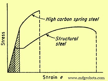
Fig 2 Comparison of the stress-strain curves for high and low toughness steels
Material ductility
Material ductility during tensile testing is generally established by measuring either the elongation to fracture or the reduction in area (RA) at fracture. In general, measurement of ductility is of interest in three ways namely (i) to indicate the extent to which a steel can be deformed without fracture in metalworking operations such as rolling, forming, or extrusion, (ii) to indicate to the designer, in a general way, the ability of the steel to flow plastically before fracture, and (iii) to serve as an indicator of changes in impurity level or processing conditions. Ductility measurement is to be specified to assess material quality even though no direct relationship exists between the ductility measurement and the performance.
Tensile ductility is a very useful measure during the assessment of material quality. Many codes and standards specify minimum values for tensile ductility. One reason for these specifications is the assurance of adequate toughness without the necessity of requiring a more costly toughness specification. Most changes in material composition and/or processing conditions produce changes in tensile ductility. Further, the metal-working features of iron and steel materials are better correlated with the ability to strain harden than with the ductility of the material. The strain-hardening abilities of many iron and steel materials used for engineering service have been quantified through the analysis of true stress-strain behaviour.
True stress-strain relationship
Conversion of engineering stress-strain behaviour to true stress-strain relationship shows that the maximum in the engineering stress-strain curve results from tensile instability, not from a decrease in the strength of the material. The drop in the engineering stress-strain curve is artificial and occurs only because stress calculation is based on the original cross-sectional area. Both testing and analysis show that, for most iron and steel materials, the tensile instability corresponds to the onset of necking in the test specimen. Necking results from strain localization. Hence, once necking is initiated, true strain cannot be calculated from sample elongation. Due to these and other analytical limitations of engineering stress-strain data, if tensile data is used to understand and predict metallurgical response during the deformation associated with fabrication processes, then true stress-true strain relationship is favoured.
The deformation which can be accommodated without fracture in a deep drawing operation varies with the material. As an example, austenitic stainless steel can be successfully drawn to 50 % RA whereas ferritic steel may fail after around 20 % to 30 % RA in similar drawing operations. Both types of steels undergo in excess of 50 % RA during tensile testing. This difference in drawability correlates with the strain-hardening exponent (n) and therefore is apparent from the slope of the true stress-strain curves for the two steels.
The n values for ferritic and austenitic steels are typically 0.25 and 0.5 respectively. A perfectly plastic material has a n value of zero and a completely elastic solid has a n value of one. Most iron and steel materials have n values between 0.1 and 0.5. Strain-hardening exponents correlate with the ability of dislocations to move around or over dislocations and other obstacles in their path. Such movement is termed ‘cross slip’. When cross slip is easy, dislocations do not pile up behind each other and n value is low. Mild steel is the example which undergoes cross slip easily. The n value increases as cross slip becomes more difficult. Cross slip is very difficult in austenitic stainless steel and the n value for this steel is around 0.5.
Tensile samples, sheets, plates, wires, rods, and other metallic sections have spot-to-spot variations in section size, YS, and other microstructural and structural in-homogeneities. Plastic deformation of these materials initiates at the locally weak regions. In the absence of strain hardening, this initial plastic strain reduces the net section size and focuses continued deformation in the weak areas. However, strain hardening causes the flow stress in the deformed region to increase. This increase in flow stress increases the load necessary for continued plastic deformation in the area and causes the deformation to spread throughout the section. The higher the n value, the greater is the increase in low stress and the greater is the tendency for plastic deformation to become uniform. This tendency has a major impact on the fabricability of the iron and steel materials.
As an example, the maximum RA which can be accommodated in a drawing operation is equal to the n value as determined from the true stress-strain behaviour of the material. Because of such correlation, the effect of process variables such as strain rate and temperature can be evaluated through tensile testing. This provides a basis to estimate the effect of process variables without direct, in-process assessment of the variables.
Temperature and strain rate effects
The YS of most iron and steel materials increases as the strain rate increases and decreases as the temperature increases. This dependence results from a combination of several metallurgical factors. As an example, dislocations are actually displacements and hence cannot move faster than the speed of sound. Also, as dislocation velocities approach the speed of sound, cross slip becomes increasingly difficult and the n value increases. This increase in the n value increases the flow stress at any given strain, thus increasing the YS of the material. A decrease in ductility and even a transition from ductile to brittle fracture can also be associated with strain rate induced increases in the YS.
In many respects, decreasing the temperature is similar to increasing the strain rate. The mobility of dislocations decreases as the temperature decreases, and hence for most of the iron and steel materials, the strength increases and the ductility decreases as the temperatures are lowered. If the reduction in dislocation mobility is adequate, the ductility can be reduced to the point of brittle fracture. Iron and steel materials which show a transition from ductile to brittle fracture when the temperature is lowered are not to be used for structural application at temperature which is below this transition temperature.
Dislocation motion is inhibited by interaction between dislocation and by the alloying or impurity (alien) atom. The effect of this interaction is both time and temperature dependent. The interaction acts to increase the YS and limit ductility. The process is most effective when there is enough time for alien atom to segregate to the dislocation and when dislocation velocity is almost equal to the diffusion velocity of the alien atom. Hence, at any given temperature, dislocation- alien atom interaction is at a maximum at some intermediate strain rate. At low strain rate, the alien atom can diffuse as rapidly as the dislocation moves and there is little or no tendency for the deformation process to force a separation of dislocation from its solute atmosphere. At high strain rates, once separation has been achieved, there is no adequate time available for the atmosphere to be re-established during the testing period. Atom movement increases with increasing temperature, thus the strain rate which allows dislocation-alien atom interaction to occur is temperature dependent. Since this interaction limits ductility, the elongation in tensile testing can show a minimum at intermediate test temperature where such interaction is very effective.
The effect of time dependent dislocation-alien atom interaction on the stress-strain curve of iron and steel materials is termed as ‘strain aging’ and ‘dynamic strain aging’. Strain aging is usually apparent when tensile testing of the material which shows a sharp YP, is interrupted. If the testing sample is unloaded after being strained past the YP, through the Lu¨ders strain region and into the strain-hardening portion of the stress-strain curve, either of two behaviours are observed when the tensile test is resumed.
If the sample is reloaded in a short period of time, the elastic portion of the reloading curve is parallel to the original elastic loading curve and plastic deformation resumes at the stress level which was reached just before the testing was interrupted. However, if the time between unloading and reloading is enough for segregation of alien atom to the dislocation, the YP reappears and plastic strain is not reinitiated when the unloading stress level is reached. This reappearance of the YP is strain aging, and the strength of the strain aging peak is dependent on both time and temperature since solute-atom diffusion and segregation to dislocation is needed for the peak to develop. If tensile strain rate is in a range where solute segregation can occur during the testing, dynamic strain aging is observed. Segregation pins the previously mobile dislocation and increases the flow stress, and when the new, higher flow stress is reached the dislocation is separated from the solute atmosphere and the flow stress decreases. This alternate increase and decrease in flow stress causes the stress-strain curve to be serrated.
Serrated flow is usual in mild steel since it contains mobile, alloy or impurity element. This effect has been initially studied in detail by Portevin and LeChatelier and is often called the Portevin-LeChatelier effect. Processing condition is to be selected to avoid strain aging effect. This selection essentially involves the control of processing strain rate and temperature.
Special testing methods
The tensile test provides basic information concerning the response of iron and steel materials to mechanical loading. Testing temperature and strain rate (or loading rate) normally is controlled due to the effects of these variables on the metallurgical response of the sample. The tensile testing usually measures strength and ductility. These parameters are frequently sensitive to the sample configuration, testing environment, and the manner in which the testing is conducted. Special tensile testing methods have been developed to measure the effect of testing/sample conditions on the strength and ductility of iron and steel materials. These testing methods include the notch tensile test and the slow-strain-rate tensile test.
Notch tensile testing
Iron and steel materials used in engineering applications is often required to withstand multi-axial loading and high stress concentration because of component configuration. Standard tensile testing measures material performance in a smooth bar sample exposed to uniaxial load. This difference between application and testing sample can reduce the ability of the standard tensile testing to predict material response under anticipated condition of application. Also, the reduction in ductility usually induced by multi-axial loading and stress concentration may not be visible in the testing result. The notched tensile testing therefore has been developed to minimize this weakness in the standard tensile testing and to examine the behaviour of material in the presence of flaws, notches, and stress concentrations.
The notched tensile sample usually contains a 60 deg notch which has a root radius of less than 0.025 mm. The stress state just below the notch tip approaches tri-axial tension, and for ductile steels this stress state normally increases the YS and decreases the ductility. This increase in YS results from the effect of stress state on dislocation dynamics. Shear stress is needed for the dislocation motion. Pure tri-axial loading does not produce any shear stress. Hence, dislocation motion at the notch tip is limited and the YS value is increased. This constraint in dislocation motion also reduces the ductility of the notched sample. For low ductility steels, the notch-induced reduction in ductility can be so severe that failure takes place before the 0.2 % offset YS is reached.
The sensitivity of iron and steel materials to notch effect is termed as the ‘notch sensitivity’. This sensitivity is quantified through the ratio of notch strength to smooth bar TS. Material which is notch sensitive has ratio less than one. Smooth bar tensile data for these materials does not satisfactory predicts the material behaviour under service conditions. Tough ductile material often is notch-strengthened and has notch sensitivity ratio greater than one, thus the standard tensile testing is a conservative predictor of performance for this material.
Slow strain rate testing
Testing environments can also have adverse effects on the tensile behaviour of iron and steel materials. The characterization of environmental effect on material response can be accomplished by conducting the tensile testing in the environment of interest. Since the severity of environmental attack usually increases with increasing time, tensile testing designed to determine environmental effects often is conducted at very low strain rate. The low strain rate increases the testing time and maximizes exposure to the testing environment. This type of testing is termed either ‘slow strain rate testing’ (SSRT) or ‘constant extension rate testing’ (CERT). Exposure to the aggressive environment can reduce the strength and/or ductility of the testing sample. This reduction can be accompanied by the onset of surface cracking and/or a change in the fracture mode. SSRT or CERT study which displays harmful effects on the tensile behaviour, establishes that the test material is susceptible to environmental degradation.
This susceptibility can cause concern over the utilization of the material in that environment. Conversely, the test can show that the tensile behaviour of the material is not influenced by the environment and is therefore suitable for application in that environment. SSRT or CERT can be used to screen materials for potential service exposures and/or examine the effects of anticipated operational changes on the materials used in process systems. In either case, the intent is to avoid materials utilization under conditions which may degrade the strength and ductility and cause premature failure. In addition to the tensile data, evidence of adverse environmental effect can also be found through examination of the fracture morphology of the testing samples of CERT and SSRT.
Fracture characteristics
Tensile fracture of ductile iron and steel materials generally initiates internally in the necked portion of the tensile bar. Particles such as inclusion, dispersed second phase, and/or precipitate can serve as the nucleation sites. The fracture process begins by the development of small hole, or micro-void, at the particle-matrix interface. Continued deformation enlarges the micro-void until, at some point in the testing process, the micro-void contacts other micro-void and coalesces. This process is termed ‘micro-void coalescence’ and gives rise to the dimpled fracture surface topography characteristic of the ductile failure processes.
The surface topography of a brittle fracture differs significantly from that of micro-void coalescence. Brittle fracture generally initiates at imperfections on the external surface of the material and propagates either by trans-granular cleavage like process or by separation along grain boundary. The resultant surface topography is either faceted, perhaps with the river like pattern typical of cleavage, or inter- granular, producing a ‘rock candy’ like appearance. The testing material can be inherently brittle or brittleness can be introduced by heat treatment, lowering of the testing temperature, the presence of an aggressive environment, and/or the presence of a sharp notch on the testing sample.
The temperature, strain rate, test environment, and other conditions, including sample surface finish for tensile testing, are generally well established. An understanding of the effects of such testing parameters on the fracture characteristics of the test sample can be very useful in the determination of the susceptibility of iron and steel materials for degradation during the fabrication or during the application. Typically, any heat treatment or testing condition which causes the fracture process to change from micro-void coalescence to a more brittle fracture mode reduces the ductility and toughness of the material and can promote early fracture under selected service conditions. Since the fracture process is very sensitive to both the metallurgical condition of the sample and the conditions of the tensile testing, characterization of the fracture surface is an important component of many tensile-testing programs.
制造工艺