

教程:您的第一个 FPGA 程序:LED 闪光灯
第 1 部分:VHDL 或 Verilog 的设计
本教程展示了以指定频率闪烁 LED 的 VHDL 和 Verilog 代码的构造。 VHDL 和 Verilog 都有显示,你可以选择你想先学习的。每当编写设计代码时,FPGA 设计人员都需要确保它按照预期的方式工作。尽管您尽了最大的努力,但您的初始设计中总会出现错误。找出这些错误的最好方法是在模拟环境中。本教程分为两个阶段:
- HDL的设计
- HDL模拟
这两个步骤对于成功的 FPGA 开发都至关重要。有时时间紧迫的 FPGA 设计人员会尝试跳过第二步,即代码仿真。然而,这是非常重要的一步!如果没有适当的模拟,您将被迫在硬件上调试代码,这可能是一项非常困难且耗时的工作。
项目要求:
设计以 100 Hz、50 Hz、10 Hz 或 1 Hz 的指定频率闪烁 LED 的 HDL 代码。对于每个闪烁频率,LED 将设置为 50% 的占空比(它将在一半时间亮起)。 LED 频率将通过作为 FPGA 输入的两个开关来选择。还有一个名为 LED_EN 的附加开关需要为“1”才能打开 LED。 FPGA 将由 25 MHz 振荡器驱动。
我们先画出频率选择器的真值表:
为了使其正常工作,将有 4 个输入和 1 个输出。信号将是:
对于该设计,有四个同时运行的计数器进程。这意味着它们都在完全相同的时间运行。他们的工作是跟踪每个不同频率看到的时钟脉冲数。即使开关没有选择该特定频率,计数器仍在运行!这就是硬件设计和并发的美妙之处。一切都在运行!最初理解这一点可能具有挑战性,但它是您需要掌握的核心概念。
开关仅用于选择要使用的输出。他们创建了所谓的多路复用器。多路复用器或简称多路复用器是一个选择器,它将选择多个输入中的一个来传播或传递到输出。它是一个组合逻辑,这意味着它不需要时钟来操作。下面是该设计的框图。花一些时间思考如何实现这个设计。尝试自己编写代码。我选择的方式可以在下面找到。
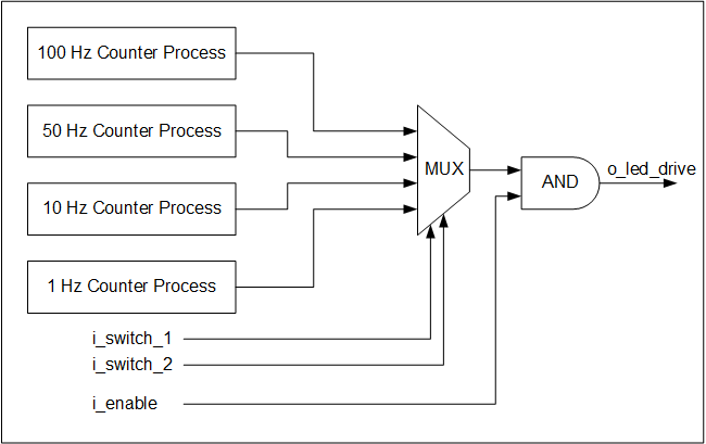 框图-LED闪烁程序
 设计的VHDL代码,tutorial_led_blink.vhd:
library ieee;
use ieee.std_logic_1164.all;
use ieee.numeric_std.all;

entity tutorial_led_blink is
  port (
    i_clock      : in  std_logic;
    i_enable     : in  std_logic;
    i_switch_1   : in  std_logic;
    i_switch_2   : in  std_logic;
    o_led_drive  : out std_logic
    );
end tutorial_led_blink;

architecture rtl of tutorial_led_blink is

  -- Constants to create the frequencies needed:
  -- Formula is: (25 MHz / 100 Hz * 50% duty cycle)
  -- So for 100 Hz: 25,000,000 / 100 * 0.5 = 125,000
  constant c_CNT_100HZ : natural := 125000;
  constant c_CNT_50HZ  : natural := 250000;
  constant c_CNT_10HZ  : natural := 1250000;
  constant c_CNT_1HZ   : natural := 12500000;


  -- These signals will be the counters:
  signal r_CNT_100HZ : natural range 0 to c_CNT_100HZ;
  signal r_CNT_50HZ  : natural range 0 to c_CNT_50HZ;
  signal r_CNT_10HZ  : natural range 0 to c_CNT_10HZ;
  signal r_CNT_1HZ   : natural range 0 to c_CNT_1HZ;

  -- These signals will toggle at the frequencies needed:
  signal r_TOGGLE_100HZ : std_logic := '0';
  signal r_TOGGLE_50HZ  : std_logic := '0';
  signal r_TOGGLE_10HZ  : std_logic := '0';
  signal r_TOGGLE_1HZ   : std_logic := '0';

  -- One bit select wire.
  signal w_LED_SELECT : std_logic;

begin

  -- All processes toggle a specific signal at a different frequency.
  -- They all run continuously even if the switches are
  -- not selecting their particular output.

  p_100_HZ : process (i_clock) is
  begin
    if rising_edge(i_clock) then
      if r_CNT_100HZ = c_CNT_100HZ-1 then  -- -1, since counter starts at 0
        r_TOGGLE_100HZ <= not r_TOGGLE_100HZ;
        r_CNT_100HZ    <= 0;
      else
        r_CNT_100HZ <= r_CNT_100HZ + 1;
      end if;
    end if;
  end process p_100_HZ;


  p_50_HZ : process (i_clock) is
  begin
    if rising_edge(i_clock) then
      if r_CNT_50HZ = c_CNT_50HZ-1 then  -- -1, since counter starts at 0
        r_TOGGLE_50HZ <= not r_TOGGLE_50HZ;
        r_CNT_50HZ    <= 0;
      else
        r_CNT_50HZ <= r_CNT_50HZ + 1;
      end if;
    end if;
  end process p_50_HZ;


  p_10_HZ : process (i_clock) is
  begin
    if rising_edge(i_clock) then
      if r_CNT_10HZ = c_CNT_10HZ-1 then  -- -1, since counter starts at 0
        r_TOGGLE_10HZ <= not r_TOGGLE_10HZ;
        r_CNT_10HZ    <= 0;
      else
        r_CNT_10HZ <= r_CNT_10HZ + 1;
      end if;
    end if;
  end process p_10_HZ;


  p_1_HZ : process (i_clock) is
  begin
    if rising_edge(i_clock) then
      if r_CNT_1HZ = c_CNT_1HZ-1 then  -- -1, since counter starts at 0
        r_TOGGLE_1HZ <= not r_TOGGLE_1HZ;
        r_CNT_1HZ    <= 0;
      else
        r_CNT_1HZ <= r_CNT_1HZ + 1;
      end if;
    end if;
  end process p_1_HZ;


  -- Create a multiplexor based on switch inputs
  w_LED_SELECT <= r_TOGGLE_100HZ when (i_switch_1 = '0' and i_switch_2 = '0') else
                  r_TOGGLE_50HZ  when (i_switch_1 = '0' and i_switch_2 = '1') else
                  r_TOGGLE_10HZ  when (i_switch_1 = '1' and i_switch_2 = '0') else
                  r_TOGGLE_1HZ;


  -- Only allow o_led_drive to drive when i_enable is high (and gate).
  o_led_drive <= w_LED_SELECT and i_enable;

end rtl;
设计的 Verilog 代码,tutorial_led_blink.v:
module tutorial_led_blink
  (
   i_clock,
   i_enable,
   i_switch_1,
   i_switch_2,
   o_led_drive
   );

  input i_clock;
  input i_enable;
  input i_switch_1;
  input i_switch_2;
  output o_led_drive;

  // Constants (parameters) to create the frequencies needed:
  // Input clock is 25 kHz, chosen arbitrarily.
  // Formula is: (25 kHz / 100 Hz * 50% duty cycle)
  // So for 100 Hz: 25,000 / 100 * 0.5 = 125
  parameter c_CNT_100HZ = 125;
  parameter c_CNT_50HZ  = 250;
  parameter c_CNT_10HZ  = 1250;
  parameter c_CNT_1HZ   = 12500;

  // These signals will be the counters:
  reg [31:0] r_CNT_100HZ = 0;
  reg [31:0] r_CNT_50HZ = 0;
  reg [31:0] r_CNT_10HZ = 0;
  reg [31:0] r_CNT_1HZ = 0;

  // These signals will toggle at the frequencies needed:
  reg 	     r_TOGGLE_100HZ = 1'b0;
  reg 	     r_TOGGLE_50HZ  = 1'b0;
  reg 	     r_TOGGLE_10HZ  = 1'b0;
  reg 	     r_TOGGLE_1HZ   = 1'b0;

  // One bit select
  reg 	     r_LED_SELECT;
  wire 	     w_LED_SELECT;


begin

  // All always blocks toggle a specific signal at a different frequency.
  // They all run continuously even if the switches are
  // not selecting their particular output.

  always @ (posedge i_clock)
    begin
      if (r_CNT_100HZ == c_CNT_100HZ-1) // -1, since counter starts at 0
        begin
          r_TOGGLE_100HZ <= !r_TOGGLE_100HZ;
          r_CNT_100HZ    <= 0;
        end
      else
        r_CNT_100HZ <= r_CNT_100HZ + 1;
    end


  always @ (posedge i_clock)
    begin
      if (r_CNT_50HZ == c_CNT_50HZ-1) // -1, since counter starts at 0
        begin
          r_TOGGLE_50HZ <= !r_TOGGLE_50HZ;
          r_CNT_50HZ    <= 0;
        end
      else
        r_CNT_50HZ <= r_CNT_50HZ + 1;
    end


  always @ (posedge i_clock)
    begin
      if (r_CNT_10HZ == c_CNT_10HZ-1) // -1, since counter starts at 0
        begin
          r_TOGGLE_10HZ <= !r_TOGGLE_10HZ;
          r_CNT_10HZ    <= 0;
        end
      else
        r_CNT_10HZ <= r_CNT_10HZ + 1;
    end


  always @ (posedge i_clock)
    begin
      if (r_CNT_1HZ == c_CNT_1HZ-1) // -1, since counter starts at 0
        begin
          r_TOGGLE_1HZ <= !r_TOGGLE_1HZ;
          r_CNT_1HZ    <= 0;
        end
      else
        r_CNT_1HZ <= r_CNT_1HZ + 1;
    end

  // Create a multiplexer based on switch inputs
  always @ (*)
  begin
    case ({i_switch_1, i_switch_2}) // Concatenation Operator { }
      2'b11 : r_LED_SELECT <= r_TOGGLE_1HZ;
      2'b10 : r_LED_SELECT <= r_TOGGLE_10HZ;
      2'b01 : r_LED_SELECT <= r_TOGGLE_50HZ;
      2'b00 : r_LED_SELECT <= r_TOGGLE_100HZ;
    endcase
  end

  assign o_led_drive = r_LED_SELECT & i_enable;

  // Alternative way to design multiplexer (same as above):
  // More compact, but harder to read, especially to those new to Verilog
  // assign w_LED_SELECT = i_switch_1 ? (i_switch_2 ? r_TOGGLE_1HZ : r_TOGGLE_10HZ) :
                                        (i_switch_2 ? r_TOGGLE_50HZ : r_TOGGLE_100HZ);
  // assign o_led_drive = w_LED_SELECT & i_enable;


end

endmodule
VHDL