

现代点唱机
组件和用品
 |
| × | 1 | |||
| × | 1 | ||||
 |
| × | 1 | |||
 |
| × | 1 | |||
| × | 1 | ||||
| × | 1 | ||||
| × | 1 | ||||
| × | 1 | ||||
| × | 1 | ||||
 |
| × | 1 | |||
| × | 1 | ||||
 |
| × | 2 | |||
| |
| × | 1 | |||
| × | 2 | ||||
| × | 1 | ||||
| × | 1 | ||||
| × | 1 | ||||
| × | 1 | ||||
 |
| × | 1 | |||
| × | 4 | ||||
| × | 8 | ||||
 |
| × | 4 | |||
| × | 1 | ||||
| × | 1 | ||||
| × | 1 | ||||
| × | 1 | ||||
| × | 1 | ||||
| × | 1 | ||||
| × | 1 | ||||
| |
| × | 12 | |||
| × | 1 | ||||
| × | 1 | ||||
| × | 1 | ||||
| × | 1 | ||||
| |
| × | 7 |
必要的工具和机器
 |
| |||
 |
| |||
 |
| |||
|
应用和在线服务
| ||||
 |
| |||
|
关于这个项目
更新:如 MagPi 杂志第 105 期所示
灵感
多年来,我一直喜欢经典的自动点唱机。早在 2014 年,我就试图制作一个,但我没有制作好看的作品的技能。快进到今天,当我学到了一些 3D 打印和设计技能。
激情、好奇心和欲望推动了这一努力。如果您想拥有这样的迷你自动点唱机,那么大众市场的产品很多 更便宜, 像这款桌面 Victrola 型号,售价 65 美元。 Hackster maker flyangel 有一个很棒的自动点唱机构建。另一方面,也有现成的现代自动点唱机更大(105 厘米/41.3 英寸高),但要贵得多,约为 795 美元。检查成本 和努力 以下部分以了解该项目涉及多少。
归因
如果没有 Marco Gregorio 在 Grabcad 上出色的 3D 自动点唱机设计,这个项目是不可能实现的。这是一件精美细致的作品,由于 Marco 没有实体自动点唱机可用于建模,而这正是他在互联网上可以找到的,因此更加令人惊叹!你应该去看看 Marco 的作品...
自动点唱机也必不可少的是 Arduino 代码,该代码用于使 LED 随音乐点亮,作者 Michael Bartlett 在 learn.sparkfun.com 上。
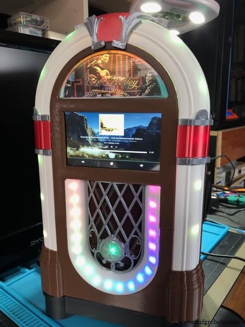
概览
这是一款由免费 Volumio 软件驱动的音乐播放器。 Volumio 具有 AirPlay、Spotify、Pandora、网络广播和您自己的音乐,可通过您的计算机、平板电脑或手机进行控制 - 只需下载并安装即可。我加了什么?一个 3D 外壳、一个触摸屏 LCD 和 LED 灯,可随着音乐点亮。 LCD 由 Raspberry Pi 3 或 4 供电。 LED 由连接在硬件堆栈顶部的 Adafruit Perma-Proto 板上的 Arduino Micro 控制:Raspberry Pi 和 IQAudio Pi Digi Amp。
我使用的是旧硬件、IQAudio 放大器板和我库存中的 Arduino Micro。在撰写本文时,IQAudio 现在是 Raspberry Pi 的一部分,Pi Digi Amp Plus 仍然可用,而且价格低于我支付的价格。 Arduino Micro 已过时,但您可以使用 Arduino Nano 或 Adafruit Itsy-Bitsy。您必须对模拟和数字引脚的使用进行调整,并将 5V 电源从 Digi Amp 馈送到子板 (Arduino)。最后,Sparkfun 声音检测器神奇地将声音转换为数字位。
Marco 为自动点唱机的所有组件提供了一个 STEP 文件,我可以将其导入到 Fusion 360 3D 设计应用程序中。我所做的是:
- 将模型从 Marco 的全尺寸模型缩放到 25%
- 查看模型组件并决定保留什么和添加什么
- 隐藏模型中我没有使用的部分
- 添加和修改功能以制作有用的外壳
- 打印形成外壳的 3D 主体
- 添加电子设备来为 Volumio 和 LED 供电
设计目标
- 大约 15 英寸/381 毫米高
- 显示正在播放/专辑封面的触摸屏
- 音质不错的扬声器
- 灯光……它必须有许多可爱的动画 LED
- 实际上看起来像 它是 3D 打印的(没有打印后处理);这意味着以不同的灯丝颜色打印
- 3D 打印时间不得超过约 12 小时(不得隔夜打印)
- 隐藏或最小化零件的接缝
技能等级:高级
- 超过 75 小时的总打印时间 用于 3D 零件
- 关键的组装——你必须让事情“恰到好处”,按照一定的顺序做事情
- 完成后可在机箱内工作的密闭空间
成本:昂贵
(所有费用为美元)
至少:
- 如果您进行后期处理,则需要 2-3 卷白色 3D 灯丝和整理用品,估计 70-90 美元
或
- 取决于您拥有什么。我只需要购买一卷红色长丝,大约 30 美元。我从 2017 年开始从事 3D 打印,这对我来说是一种重要的消遣。我的库存中有银色、白色、棕色和黑色长丝。那些,加上一卷红色将至少 大约 100 美元。
- Arduino Nano 或 Adafruit Mini Metro,大约 20 美元(我的库存中有 Arduino Micro)
- Adafruit Raspberry Pi Perma Proto 帽子 5 美元
- HDMI 触摸屏 (Uctronics) 5 英寸,53 美元
- Raspberry Pi 3B Plus 35 美元(现货)
- Parts Express Dayton Audio RS100-8 扬声器,2 个,共 60 美元(库存)
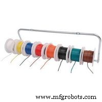
- Parts Express 扬声器线,18AWG 约 20 美元(库存)
- Parts Express 扬声器格栅布,30 美元(库存)
HDMI 电缆/连接器、开关、安装硬件、跳线、母接头等另外 40 美元或更多。我有很多库存。对我来说,目前的自付费用约为 150 美元,分几个月摊开,因为我手头有很多用品。如果你必须出去购买所有这些用品......好吧,你自己算算。
对我来说,付出的代价是值得的。
努力
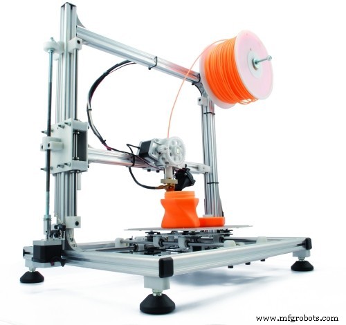
3D 打印需要 75 小时或更长时间,具体取决于您的打印机。有 21 个不同的部分,其中大约 12 个需要花费数小时才能打印出来。其余部分每个大约需要 1-2 小时。那是假设您没有要打印的东西。
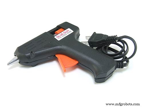
我使用热胶分 4 个阶段将外壳的各个部分准备和粘合在一起。假设 3-4 小时。为了那个原因。粘贴 LED 灯串需要大约一个小时的设置和执行时间。还有小装饰件(用CA胶)的精密粘合,完成点唱机。
对于电子产品,至少需要 5 小时才能:
- 安装 Volumio
- 安装 Arduino 草图
- 布局和焊接电路板
- 在最终组装之前测试一切是否正常!
- 安装液晶面板
- 在堆栈中安装 RPi、IQAudio Digi Amp Plus 和 Perma Proto 板
- 焊接和安装开关和电源插孔
- 安装扬声器和扬声器线
最终粘合可能需要 1-2 小时。
总而言之,除了打印所有零件的时间外,组装可能需要大约 12 小时或更长时间。
下载
文档、代码和 3D 打印文件可在 github 上找到。
3D 打印文件也可以在 thingiverse 上找到。
3D打印
总共有 21 个单独的 STL 部件文件。有些部分需要 2 份/打印。
开始使用
请务必仔细阅读“事物”部分中的注释。它们提供了有关要使用的确切组件的必要信息。如果您进行零件替换,则必须弄清楚需要进行哪些更改。
为确保一切正常,请在组装外壳之前测试所有电子设备是否能正常工作:
- 安装和配置 Volumio
- 焊接电路板
- 连接组件:NeoPixel、慢衰落 RGB LED 和开关
- 向电路板添加组件
- 从github下载Arduino草图
- 将草图上传到安装在板上的 Arduino
- 尝试一下
安装 Volumio
转到 Volumio 入门页面并按照 Raspberry Pi 的设置指南进行操作。要开始测试,请将 IQAudio Pi Digi Amp 安装在 Raspberry Pi 上,将放大器插入 Pi 上的母接头并使用从 Pi 到 IQAudio Amp 的支架,如下图所示。稍后,请参考本指南将它们安装到 3D 打印点唱机底部。
_9H4kWWGtUT.jpeg?auto=compress%2Cformat&w=680&h=510&fit=max)
将两根母对公跳线连接到 Digi Amp Plus 的 +5V 和 GND 端子,如下图所示。这些将连接到 Perma-Proto 板,以直接从 Pi Digi Amp Plus 为 NeoPixel 供电。
最新型号的 Digi Amp 暴露了 Pi 的所有插头引脚,因此 5V 和 GND 引脚将位于标准 Pi 插头引脚位置。
_4dxCv32yCp.jpeg?auto=compress%2Cformat&w=680&h=510&fit=max)
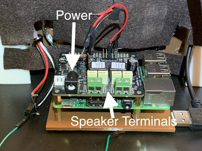
要设置扬声器,请剪断两对长约 7 英寸/18 厘米的扬声器线 (14-26 AWG),然后连接到扬声器端子和 IQAudio 螺丝端子。 Pi 将由 IQAudio 供电 - 请勿 将电源插入 Pi 电源插孔。将电源块插入 IQaudio 并尝试从 volumio 播放一些网络广播。
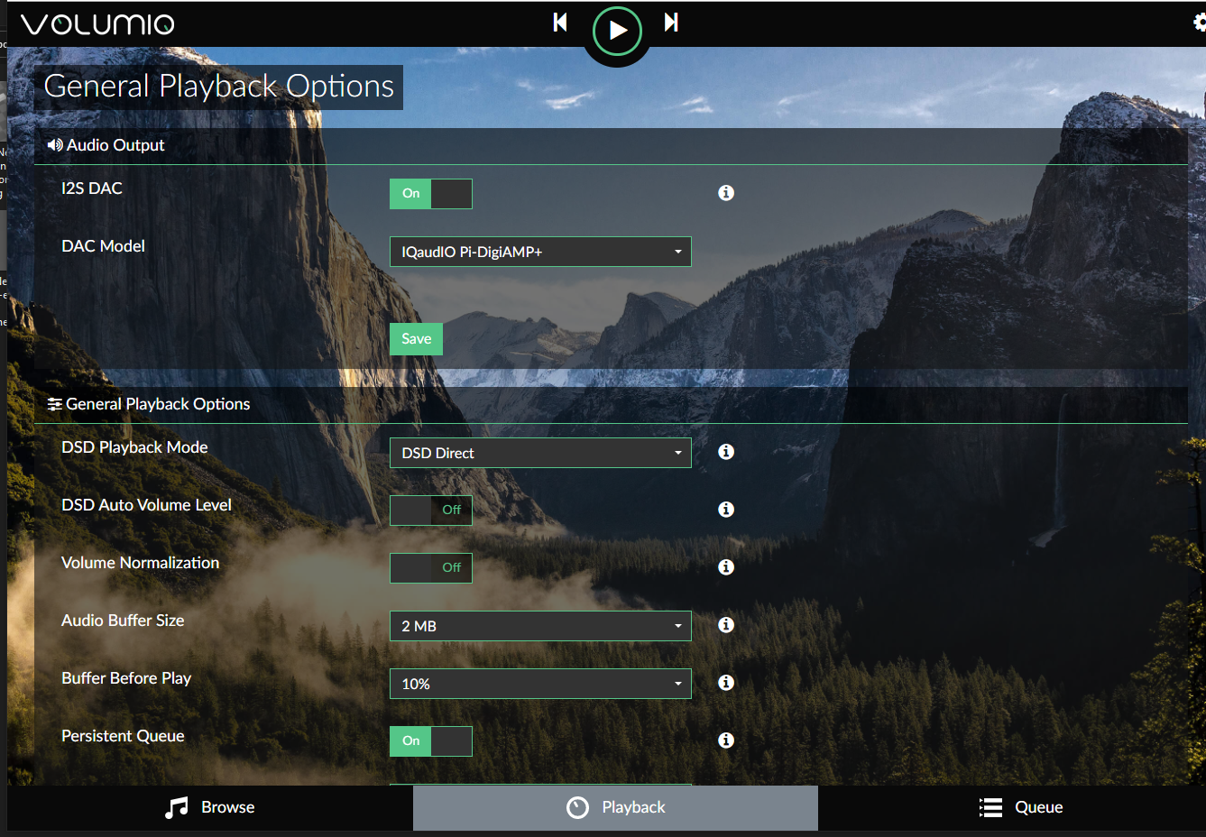
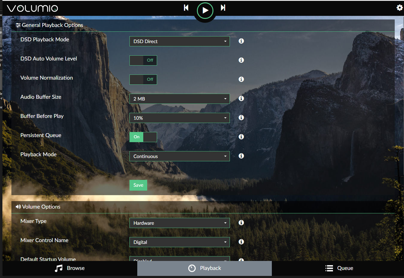
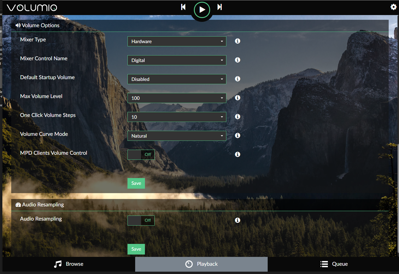
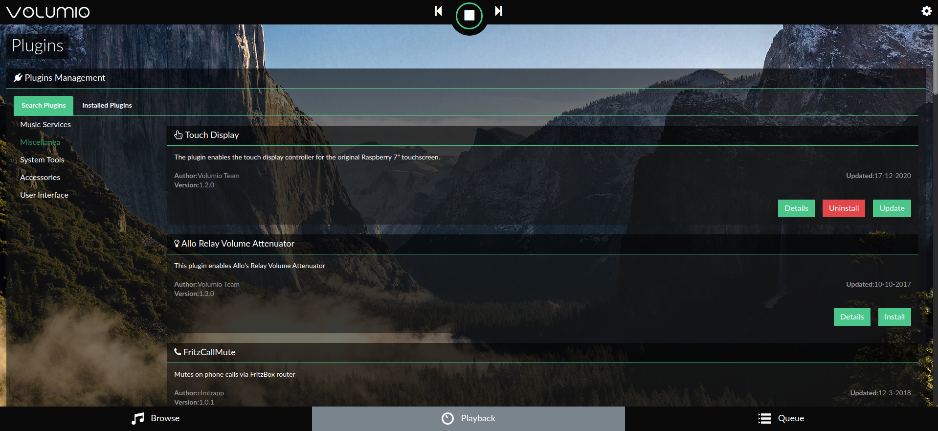
下面的图库显示了 IQAudio Pi Digi Amp Plus 和触摸屏插件(设置/插件/杂项)的 Volumio 设置:
要开始使用 Volumio,请查看快速入门指南和使用 Volumio 的第一步。
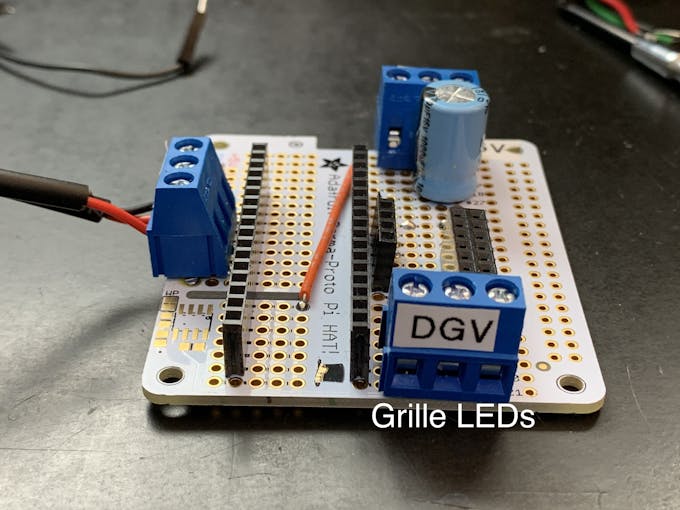
准备电路板
当堆叠在 Pi 和 IQAudio 放大器顶部时,Adafruit Perma-proto 板的外形非常适合,并且为 Arduino 制作了一个很好的载体/子板。
该板仅连接到 IQAudio 5V 和 GND 以供电。因此,没有使用通常用于连接 Pi 的母头。
为了最好地利用原型板上的可用空间,调整板的方向,使标有“3.3V”的导轨位于顶部。
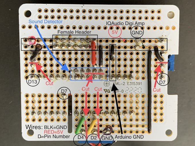
我正在以比点对点接线更不常见的方式修改原型板:
- 3.3V 电压轨实际上将用于 5V 输入 .
- 砧板痕迹 在一个列中放置多个引脚连接
- 切割轨道痕迹 在较低的、标有电路板的 5V 导轨上,在一行中添加多个引脚
这些东西有助于在填充时布局良好的电路板。
有关接线连接和修改的信息,请参阅此照片库:
 =noscript1>
 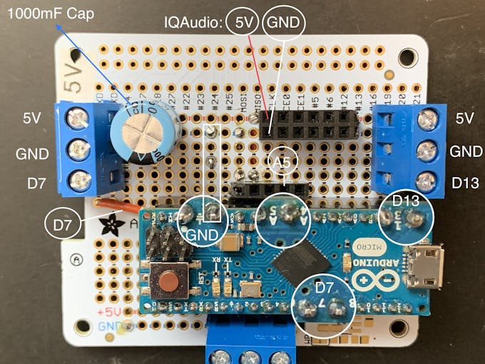 no=script1">
 注意: 3 针端子的针脚间距为 5.08 毫米。这恰好是原型板上标准 2.54mm 过孔间距的 2 倍。因此,螺钉端子/引脚各相隔 2 个板通孔。电路板布局和走线切割取决于该间距。您无法在不改变电路板布局的情况下替代 3 针/2.54mm 间距端子。
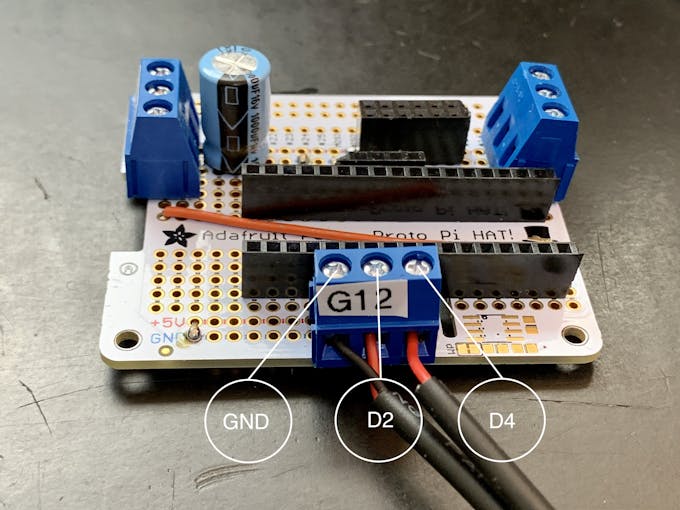
动画选择开关
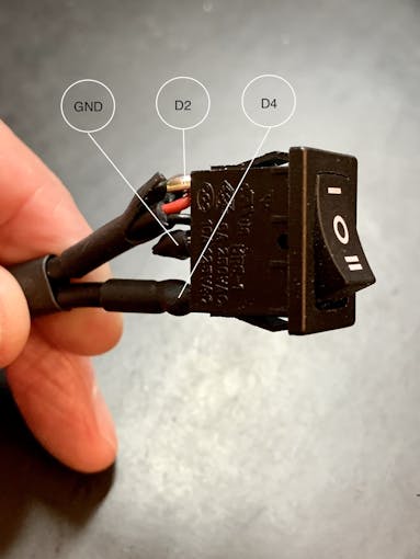
您还需要连接一个三位翘板开关,如图所示。为这个开关剪下 3 根约 7 英寸/18 厘米的连接线,最好是两根黑色 (GND) 和一根红色 (+V)。
下面详细介绍这个开关。
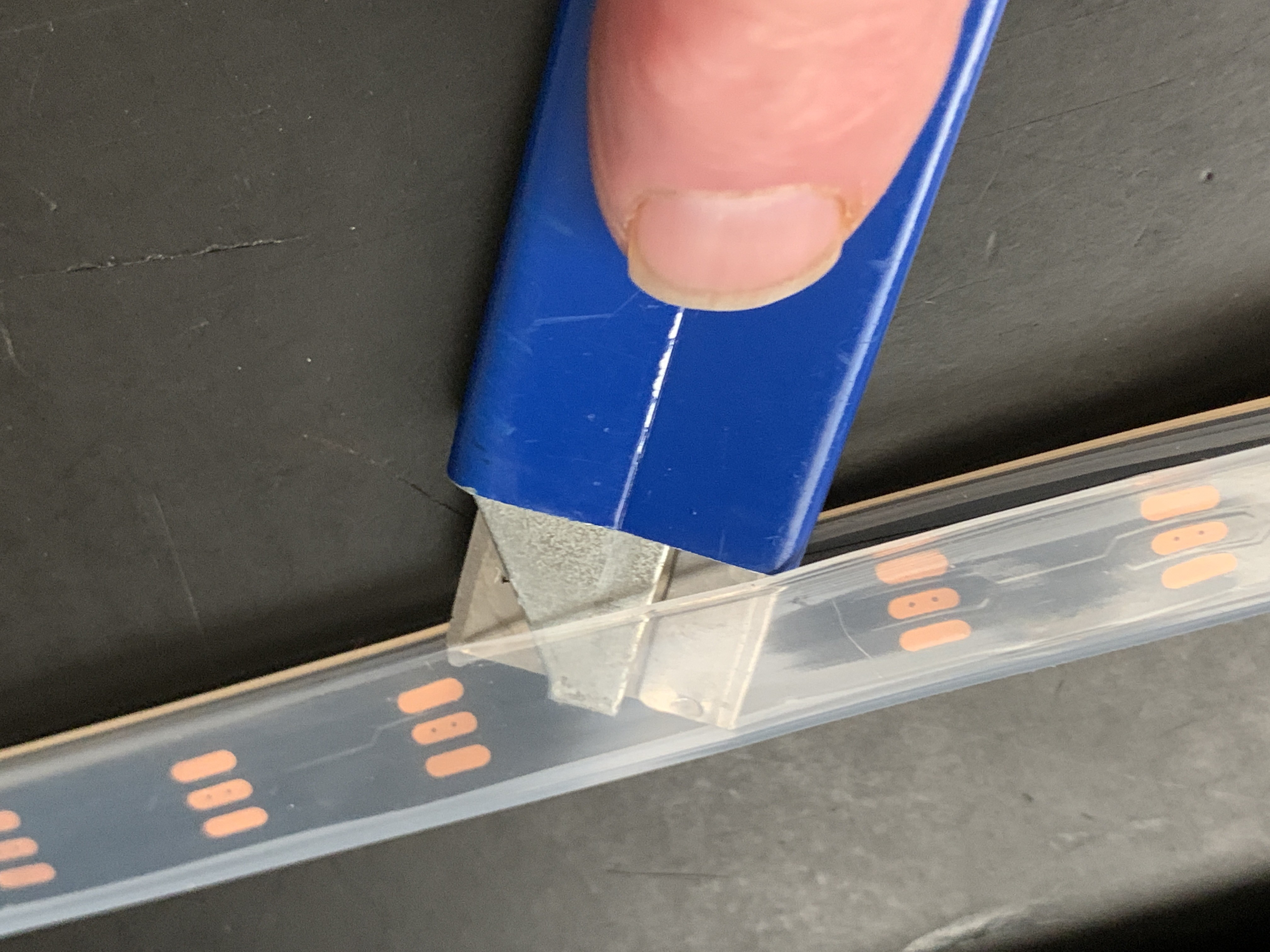
新像素
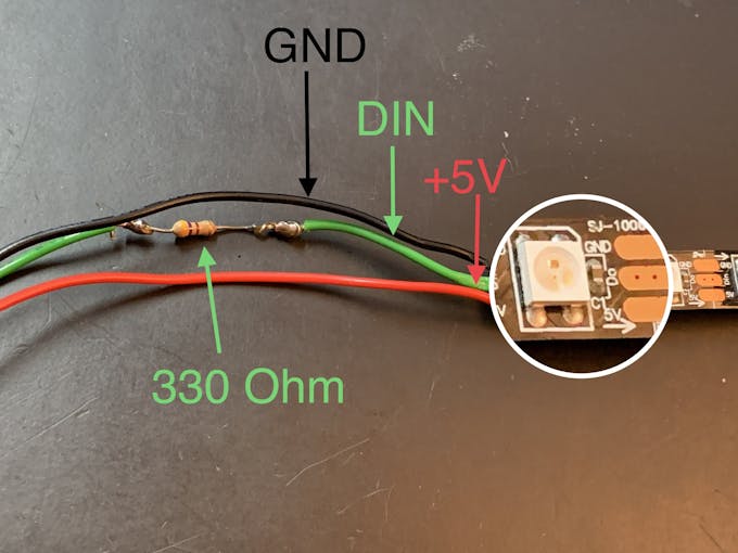
从一米的 Neopixel 绳子上取下硅胶套。将 Neopixel 条带切割成两部分,一部分是 36 个 LED,另一部分是 22 个 LED。短条将围绕前格栅。 36 个 LED 长度的灯条将位于外管(霓虹灯管)中。为每根弦剪 3 根约 7 英寸/18 厘米的连接线(您可以稍后缩短它们)。用 GND、+V 和 DIN 线连接每个部分,确保匹配字符串上的 DIN 方向。添加一个与 DIN 连接串联的电阻器(330 欧姆有效)。
星光
在前格栅中,有一个形状像 6 角星(星光)的 3D 打印插件。使用 +V 和 GND 的 RGB 慢衰落 LED 安装在此 Star Light 后面,插入 3D 打印挡板以防止光流失。在 +V 跨接线上插入 120 欧姆电阻器。这将使 LED 的电流从 5V 下降到大约 3.4V。这将用于下面的组装/格栅布部分。
阿杜诺
如果您尚未安装 Arduino IDE,请按照这些说明下载并安装它。
您需要 Neopixel 库来使 LED 工作。
声音反应 Neopixels 是基于 Michael Bartlett 在 Sparkfun 上的交互式 LED 音乐展示台草图。我使用了没有按钮的“Full Visualizer”,我添加了一个具有三个功能的摇杆开关:
- LED 对音乐做出反应 - 开关位置 1
- 呈变色“追光”模式的 LED,声音无反应 - 开关位置 2
- LED 关闭 - 切换位置中心
除非连接开关,否则 LED 不会工作。
从 github 下载 Jukebox LED 草图。
连接
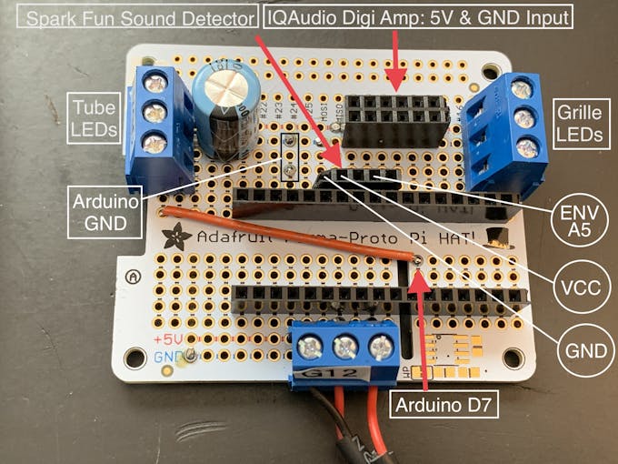
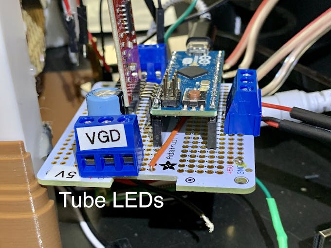
- 将您的 Arduino 安装在原型板母接头上
- 将 36 个 LED 灯条连接到连接到数字引脚 7 的端子上。
- 将 22-LED 灯条连接到连接到数字引脚 13 的端子
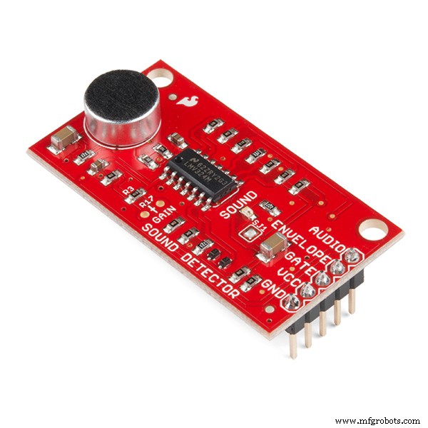
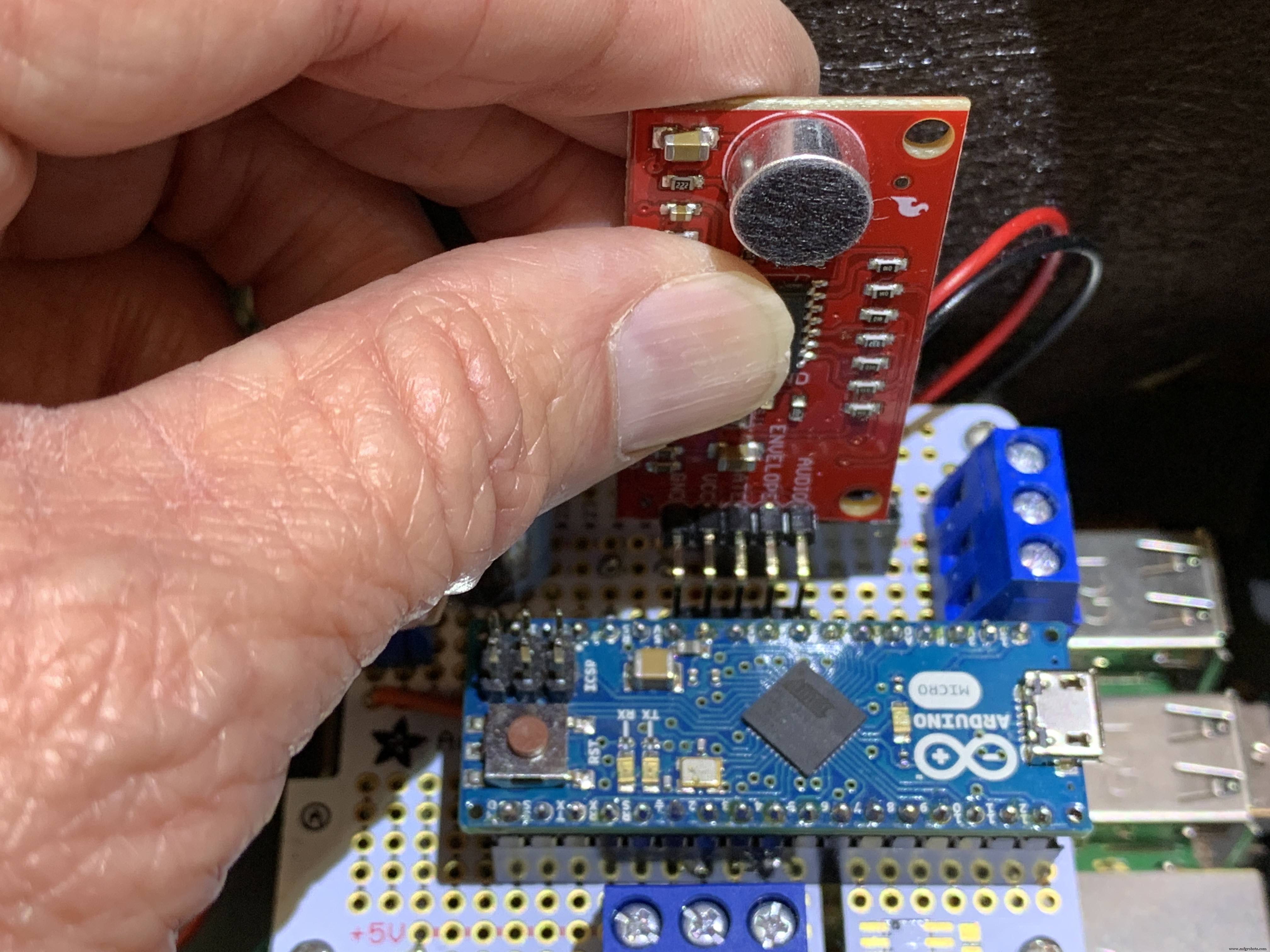
- 插入 Sparkfun 声音检测器。
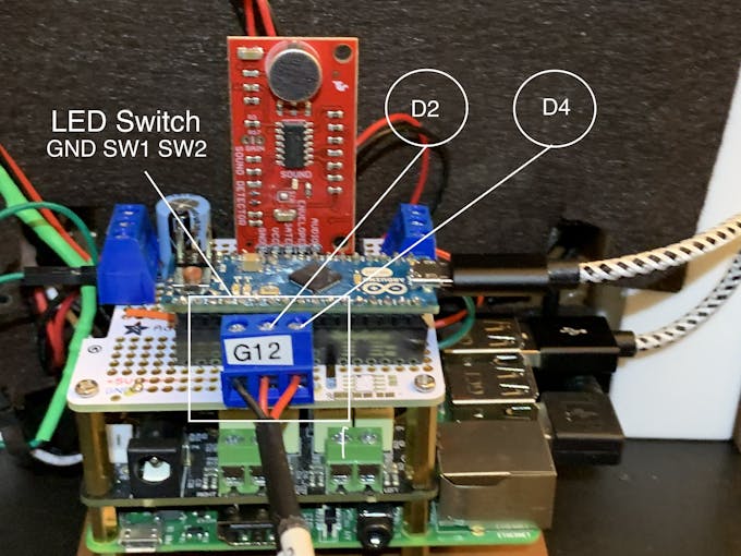
- 连接翘板开关:中心极连接到 GND,位置 1 连接到引脚 D2,位置 2 连接到引脚 D4
- 将 IQAudio Digi Amp Plus +V 和 GND 连接到 Perma Proto 板上 5V 导轨的母接头(如上图所示)
- 将慢渐变 RGB 连接到 +V 和 GND 母头

将点唱机 LED 草图上传到您的 Arduino 板。格栅 LED 运行草图设置功能中的 RainbowCycle 例程,这需要一些时间。所以声音反应 LED 不会立即工作。设置功能运行后,格栅 LED 将始终保持亮起,不受翘板开关位置的影响。播放来自 Volumio 的音乐时,霓虹灯管应该对音乐做出反应,并将 3 位摇杆开关设置为位置 1。 Switch position two passes a color-wheel/chaser pattern through the Neon tubes. Center position on this switch turns the Neon LEDs off.
3D Printing
Check the docs folder of the github download for part identification (Parts List) and Print Times for each part. There are also screenshots of the Prusa Slicer parameters and orientation to guide how to print each part. Find those in the 3D-Prints folder.
NOTE: All images are of the prototype jukebox I built. These will look different from the published Fusion 360 design archive and STL files. The final release STL files include improvements for the following:
- Increase the size of the bezel on the LCD touch screen
- Increase the size of the mounting plate to allow more clearance
- Remove the 3D printed standoffs on the mounting plate and just use holes with screws inserted from the bottom of the mounting plate
- Simplified the back cover
Assembly
Tools
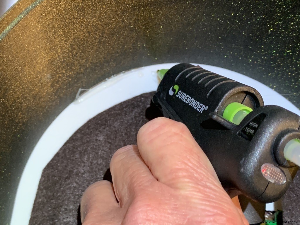
I used a fine-tipped hot glue gun so I could get into smaller spaces. These use smaller diameter glue sticks, and lots of them.
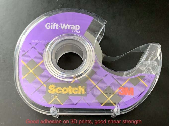
I used some tape I had on hand to temporarily hold the parts together for gluing. I found Scotch Gift-Wrap tape was actually pretty good for this. It has good adhesion and strong shear strength.
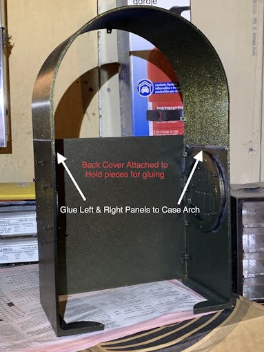
外壳
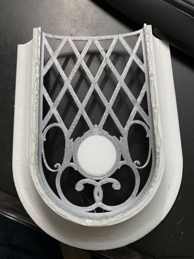
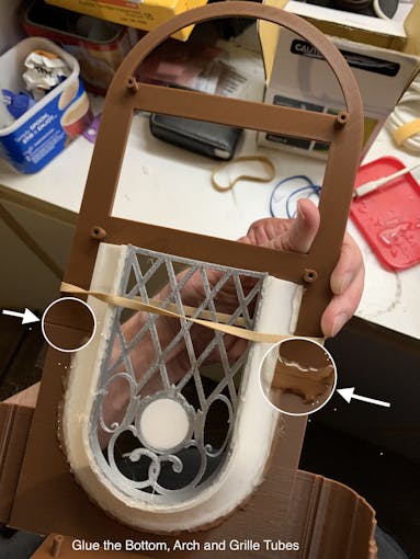
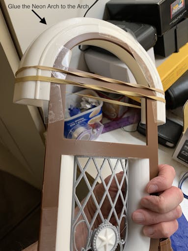
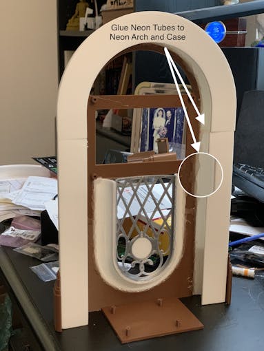
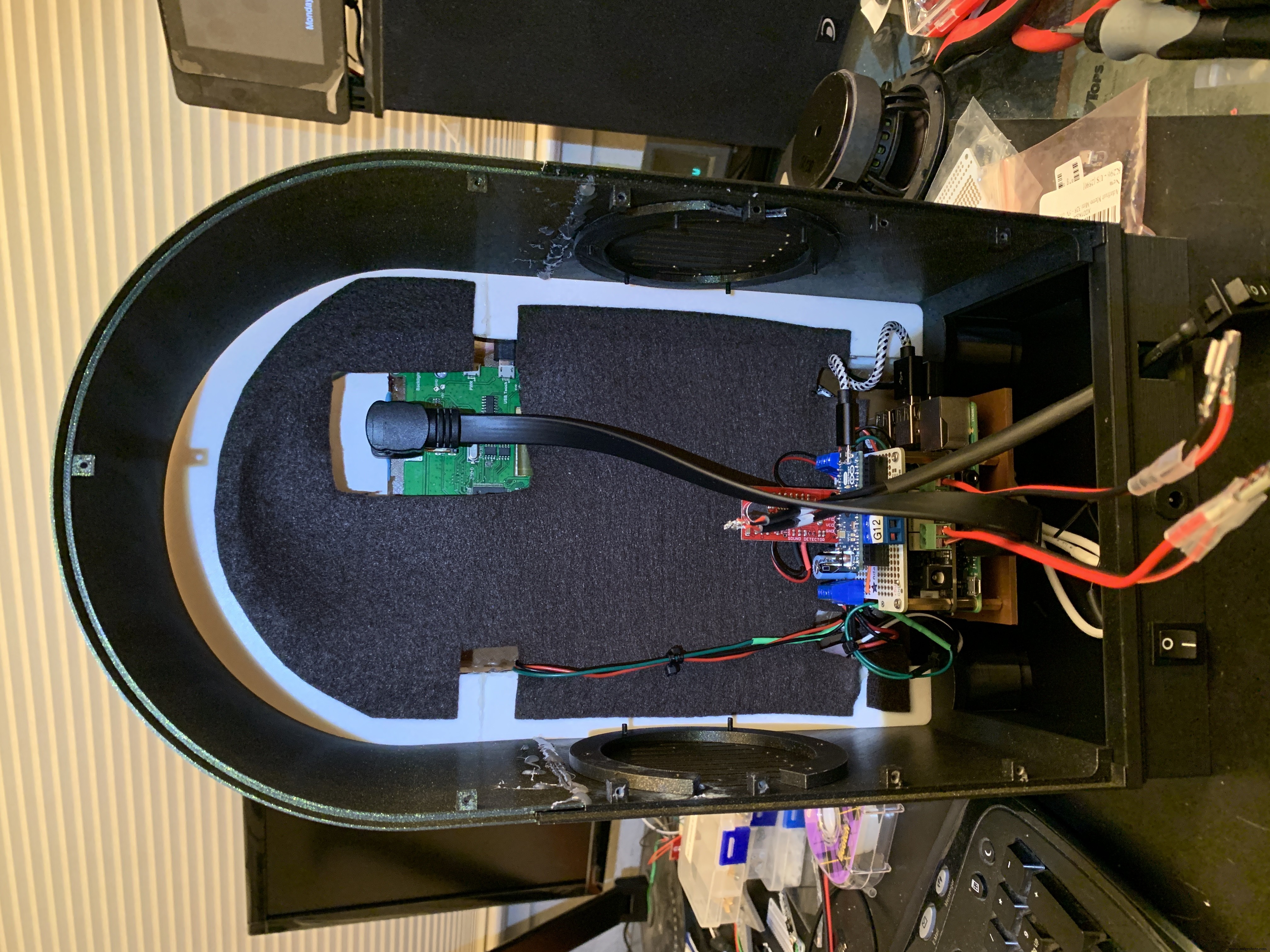
The parts are glued in starting from the inside, the Grille, and moving to the outside, the Neon Tubes, as shown in the video below.
Pause after gluing the Neon Tubes and mount the following hardware. This will give you more space to work in, before you glue in the back case. Refer to the Assembly Gallery photos below for details.
- Acrylic Window with photo
- NeoPixels
- LCD Touch Screen
- Grille Cloth and Star Light Holder
- Raspberry Pi/IQAudio Pi Digi Amp/Arduino
- Adhesive Felt (or paper) backing
- Base with switches
Then continue gluing the Case and Base to the other assembled parts.
After the case is fully assembled and glued together, mount the Speakers and add Decorations.
There is an optional two-piece 3D printed case cover that screws into the back of the case.
_k2oC39lKQk.jpeg?auto=compress%2Cformat&w=680&h=510&fit=max)
Mounting the Hardware
In the following, all the hardware mentioned is found in the "Things" section.
“Right” and “Left“ are your right and left as you face the front of the jukebox.
Acrylic Window and Photo
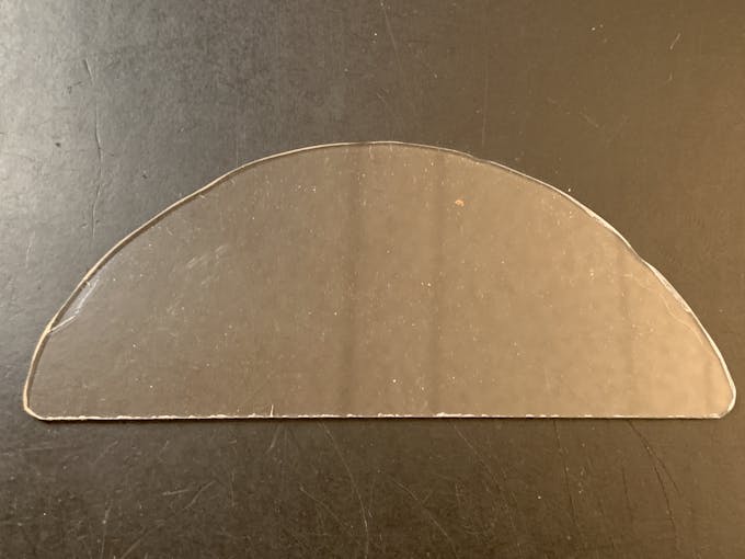
Use a rotary tool (eg., Dremel) at slow speed to cut a piece of clear acrylic. There is a template for this in the github download. Tape the template down on the acrylic and cut around the outside. Sand the edges and use CA to glue into the top of the Arch. Print a photo of your choice that will fill up the visible area and glue that in back of the acrylic.
NeoPixels
Glue the long LED strip edge-on to the Neon Tubes, so that the LEDs are facing inward to the Tubes. There is a small space between the LED and the edge of the strip that can help fit the string against the Neon Tubes. Align that to glue down.
The Grille Tube NeoPixels will be glued onto the Left and Right Bottom, with a "U" shape near the board mounting plate. Hold the strip down with pieces of tape and tack spots with hot glue. When those are solid, remove the tape and fill in the spots where the tape was with more glue.
LCD Touch Screen
Screw the Touch Screen into the mounting posts at the top of the Arch, below the Acrylic window. The HDMI Touch Screen input is on the top of the screen. You need to insert a 90 degree to 270 degree HDMI adapter there, Plug the HDMI 1 ft. Male-to-Male flat cable into the adapter. The other end plugs into a Raspberry Pi 3. (If you're using a Raspberry Pi 4, you need a different cable that has a Micro HDMI in one end). Insert the Left-angle Micro USB to the Touch port on the LCD, and the USB-A end to a Raspberry Pi port. Thread this cable through the left Neon Tube.
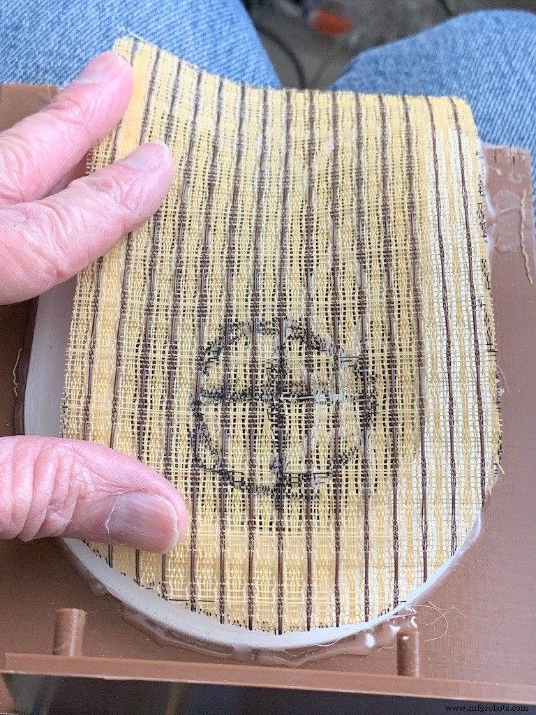
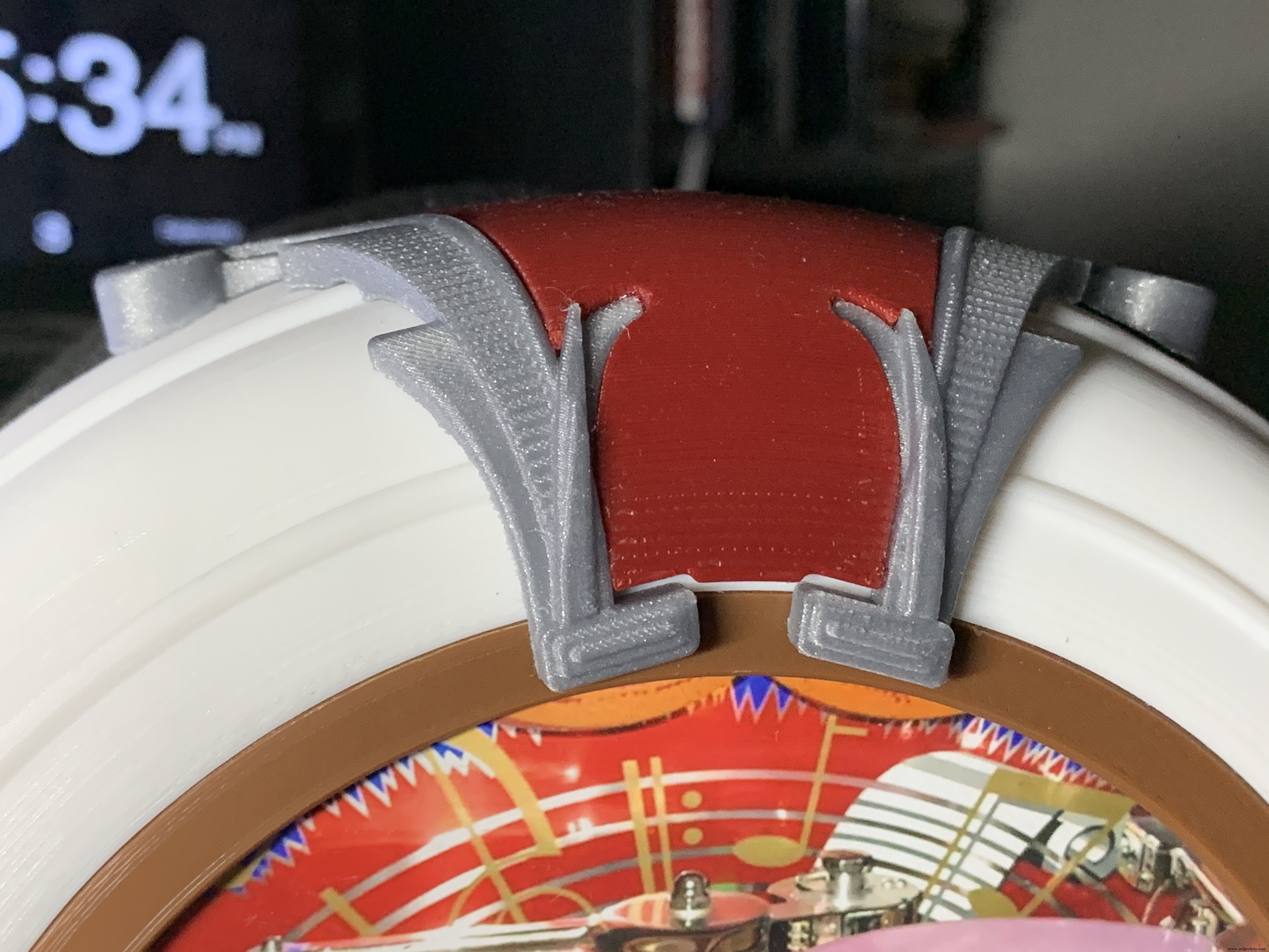
Grille Cloth and Star Light Holder
The Grille will be backed with "speaker cloth" to hide the inside of the jukebox. There will be an LED holder behind the Star Light to prevent light bleed, and a hole needs to be cut into the cloth for that.
Cut a piece of speaker cloth large enough to cover the Grille and the edges of the Grille tubes. Use the Star Light LED 3D printed holder as a guide and mark the speaker cloth in a circle for the outside of the holder. Mark a cross in the center of the circle Cut the two lines of the cross to make 4 sections. Cut the rounded part of each section to make a hole for the LED holder.
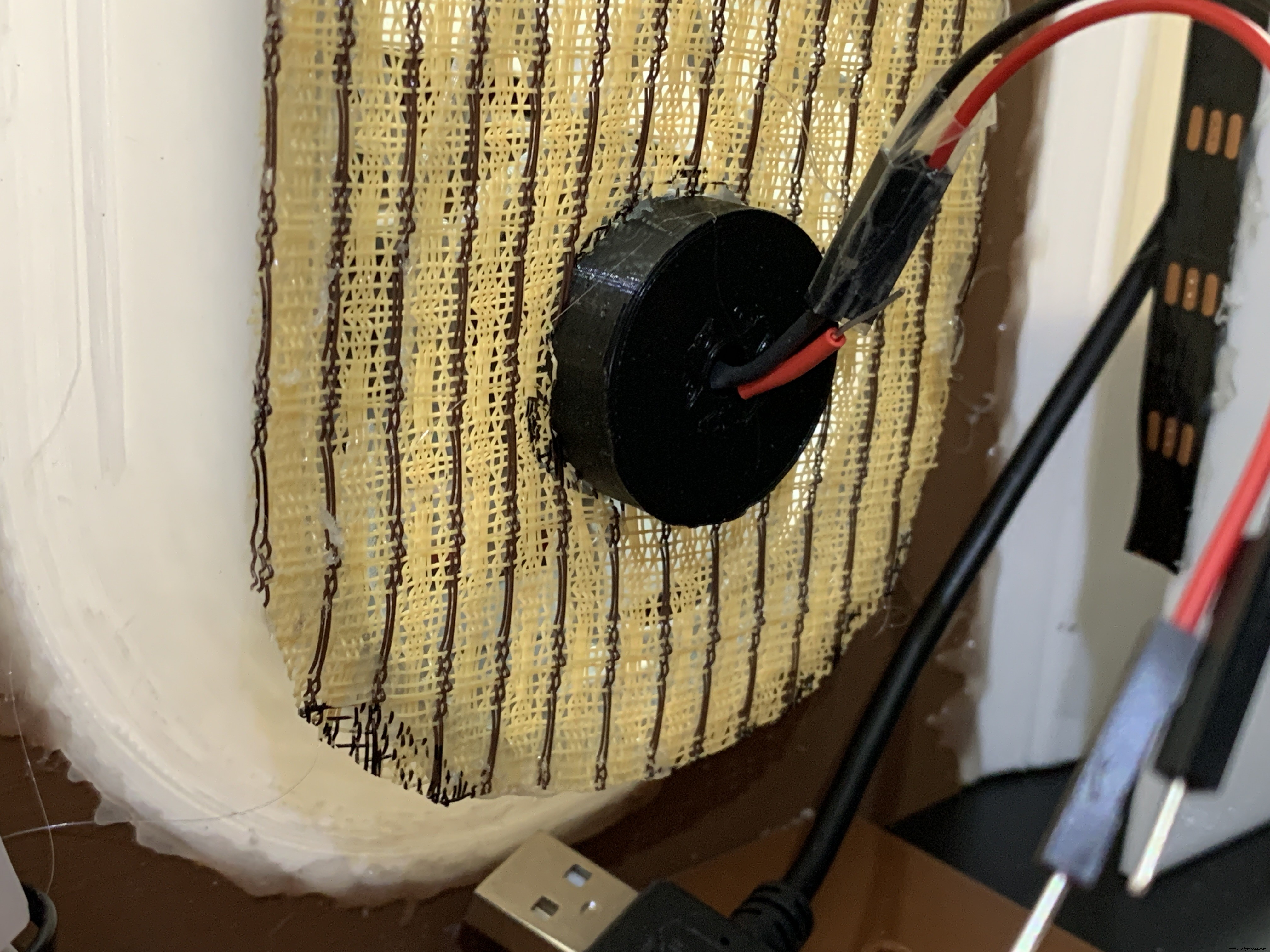
Mount the color-changing LED mentioned in the section Prepare the Circuit Board/Star Light, above. Insert the LED into the holder and glue it to the Star Light. CA will work well here.
With the LED holder glued in place, fit the speaker cloth over the holder and the Grille. Stretch and glue the edges of the cloth to the Grille Tubes.
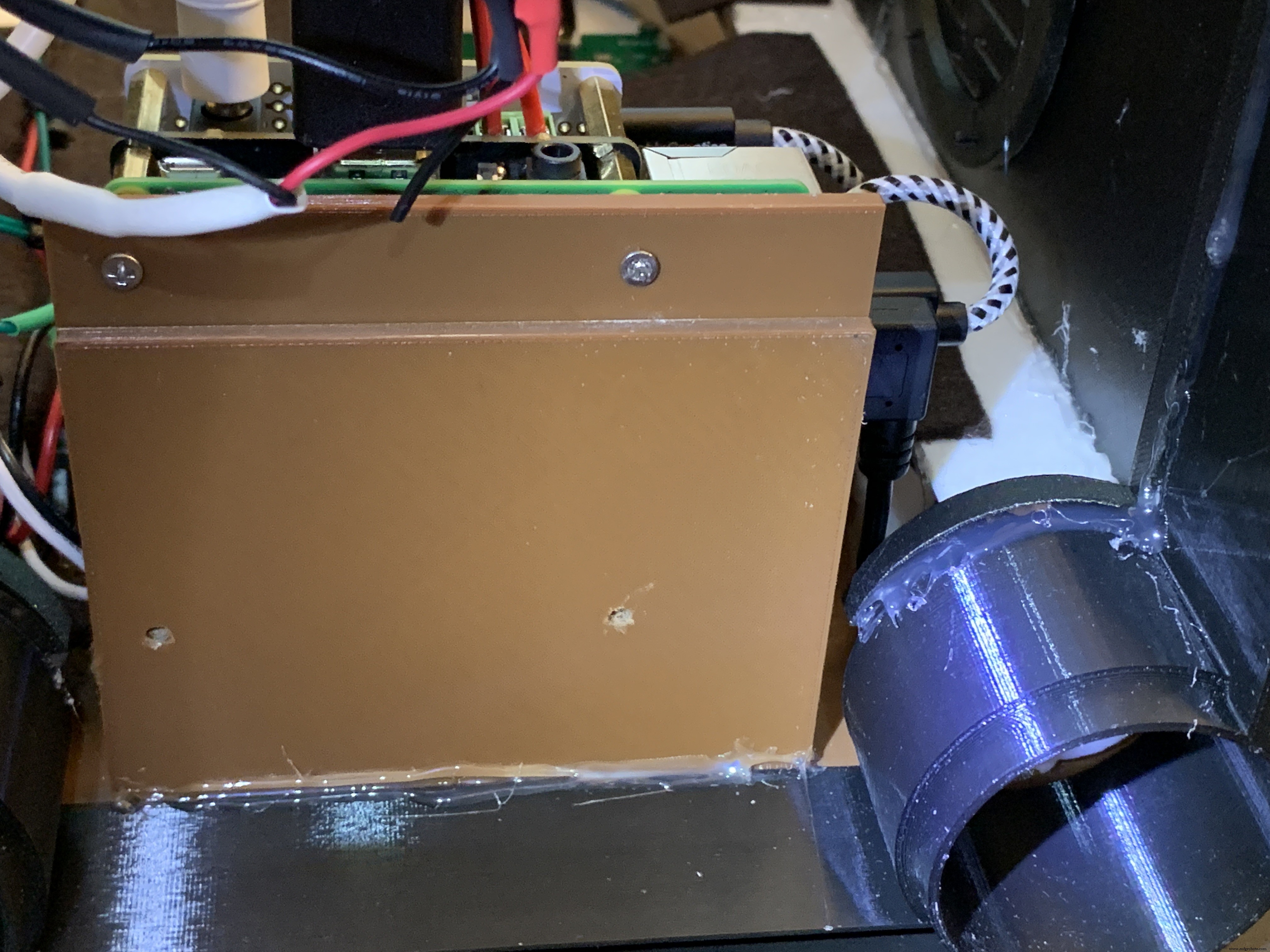
Raspberry Pi/IQAudio Pi Digi Amp/Arduino
Mount the Pi and other boards (you assembled and tested it in Getting Started, Right ?) onto the mounting plate with screws into the Pi's 5mm bottom standoffs. Plug the LCD HDMI and USB cables into the mounted Pi. There's an additional 6 inch Micro USB to Micro A cable. Plug the Micro end into the Arduino and the other end into the Pi to power the Arduino.
The Star Light +5V and GND plug into the power from the Digi Amp Plus +5V/GND rails.
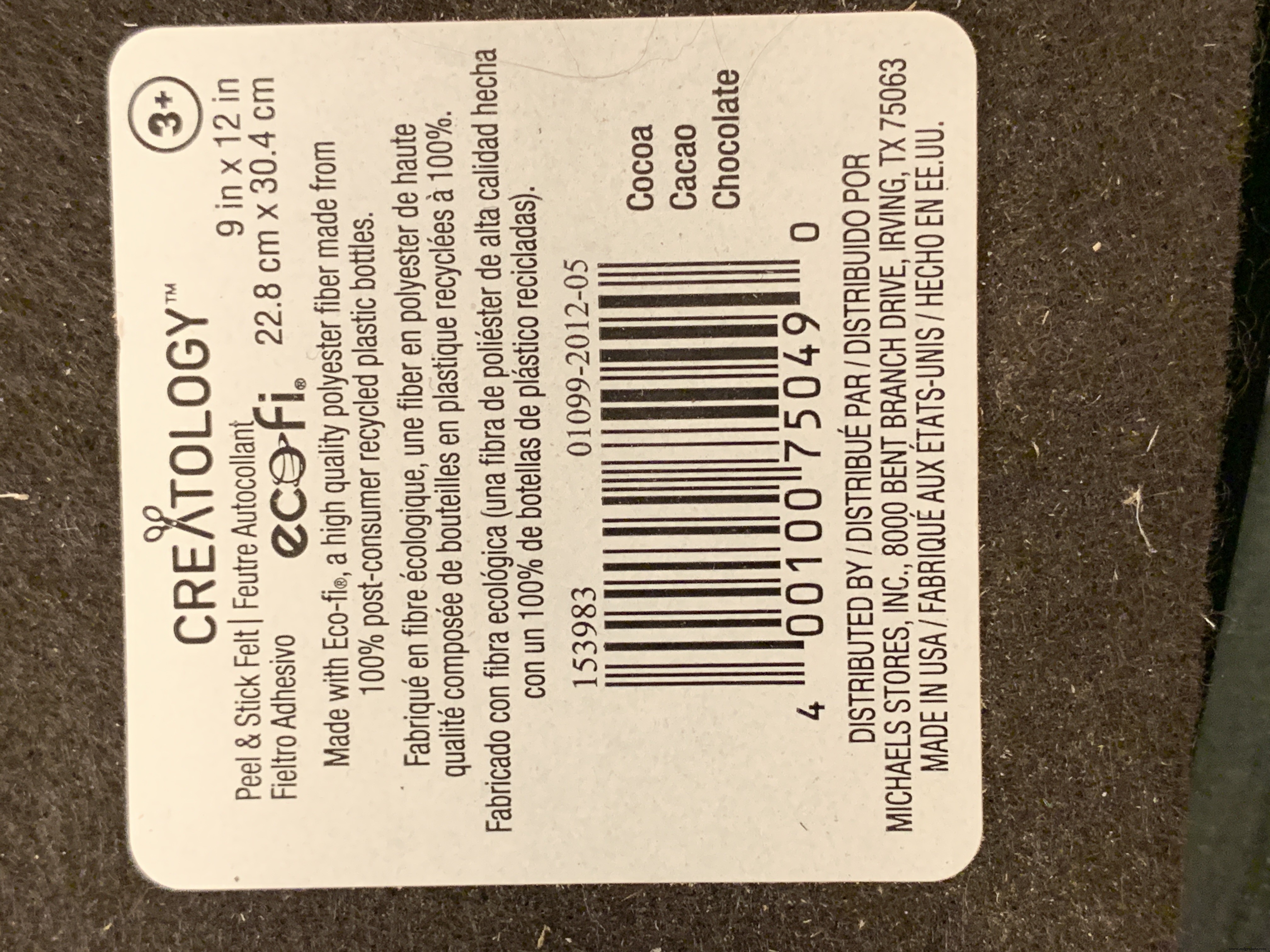
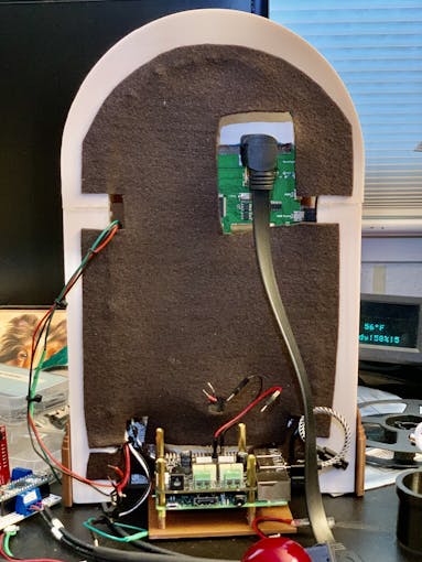
Adhesive Felt
To prevent light bleed, cover the inside with craft felt, which has its own adhesive backing Test fit the felt and cut holes to allow for cables and wires to pass through.
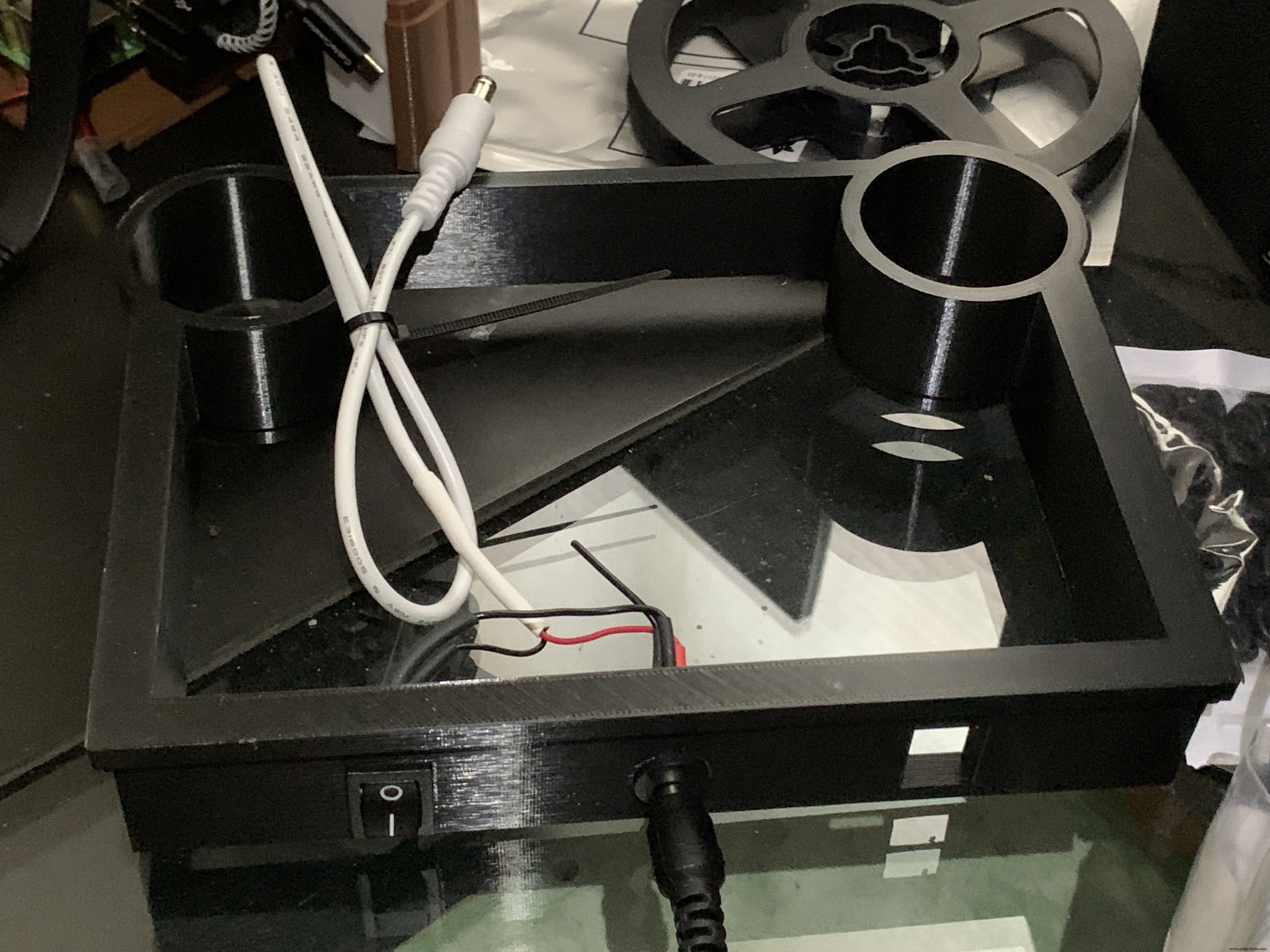
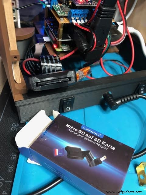
Base with Switches
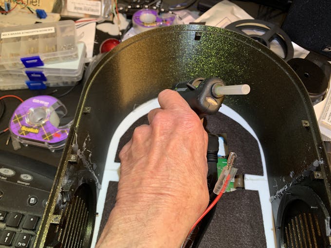
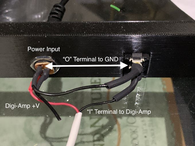
In addition to the Animation Selector Switch, there is an on-off rocker switch that is connected to a panel-mount jack.
Cut one GND (black) wire at least 80 mm long for this switch. Strip the insulating jacket off the power extension cable (white) in pictures about 80 mm long to expose a red and a black wire. Insert the barrel power connector and the on-off rocker switch into the base.
Solder the cut black wire to the terminal marked "O" on one end, the other end to the active GND pin on the barrel power connector. The other terminal "I" is soldered to the GND (black) of the power extension cable for the Digi Amp Plus Finally, the +V (red) of the power extension cable is soldered to the +V terminal of the barrel connector.
Plug the extension connector into the Pi Digi Amp Plus. Glue the Base onto the Bottom and Case.
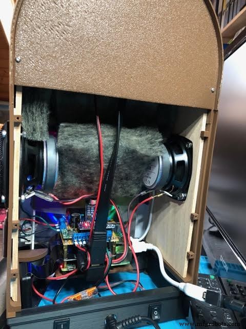
Speakers
The Dayton Audio RS100-8 speakers have a cone in the middle that prevents them from being mounted flush to a solid grille, as on this jukebox. If you're using these speakers (or some where the center protrudes), you'll have to use a mounting ring (3D file supplied) so the speakers can mount properly.
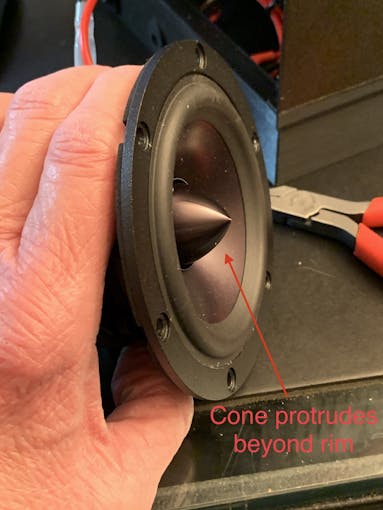
For the last step of assembly, screw the speakers in with 15 mm M2.5 metal screws and nuts.
Tip: To make assembly easier, mount the speaker rings to the case with the screws pushed in for alignment in the holes. Tack down with hot glue or CA glue. When solid, mount the speakers to the rings.
I had pretty good luck holding the tiny nuts down with my index finger and turning the screw to get the nuts started.
However, there is one screw hole straight back on each side that has very little clearance. It is hard to get the nut started on that screw. Putting blu-tack or tape on the nut may help position it to get it started.
Eventually, I did get all the nuts fastened.
Decorations
There are decorations on top and the two sides of the jukebox, with details in the github 3D Parts List document:
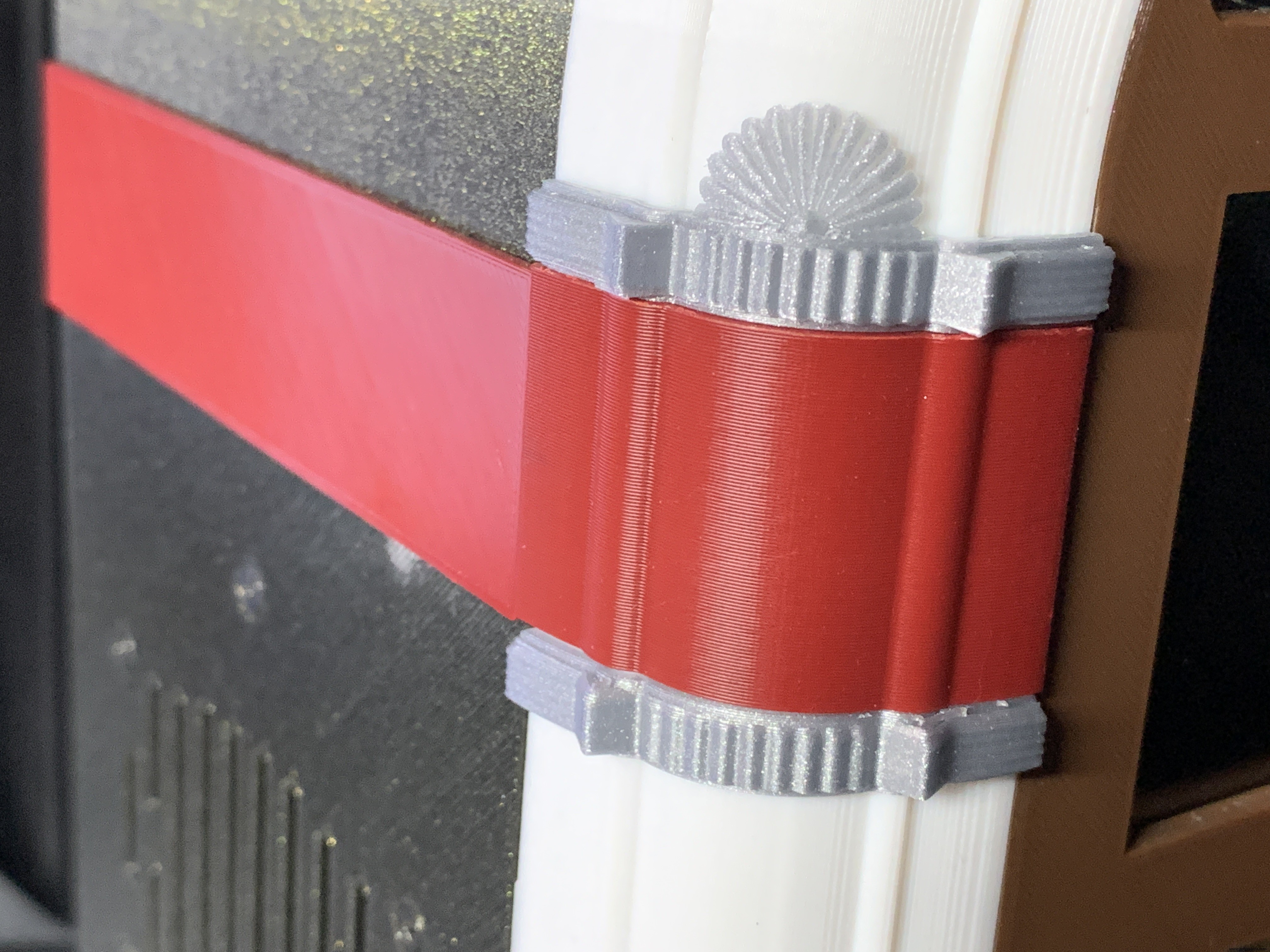
- Neon Tube Red Cover
- Neon Tube Fan Decoration
- Neon Tube Ornament
- Case Joint Cover
- Top Red Ornament
- Top Ornament
Repeat for Left &Right:
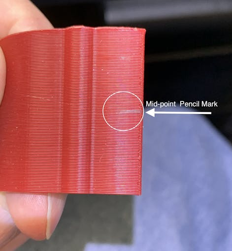
For the Neon Tubes, use a small ruler to mark the halfway point on the side of the Red Cover with a pencil. Then, match that to the Neon Tube joints and glue with CA.
The long Case Joint Cover aligns to the Neon Tube Red Cover and glues down to the case.
Gllue the Fan Decoration and Ornament at the top and bottom of the Red Cover
The Top Ornament (2 separate pieces) fits into the Top Red Ornament and is glued together as an assembly.
For alignment, make a pencil mark midway at the top of the Arch and another mark midway on the Top Red Cover. Align these two marks and glue.
Operation
Volumio has a fairly intuitive user interface that's easy to use.
To get started, press/select the 'Home' icon or the 'Browse' button from the 'Playback' window..You'll see something like the image below, depending on what options you have installed.
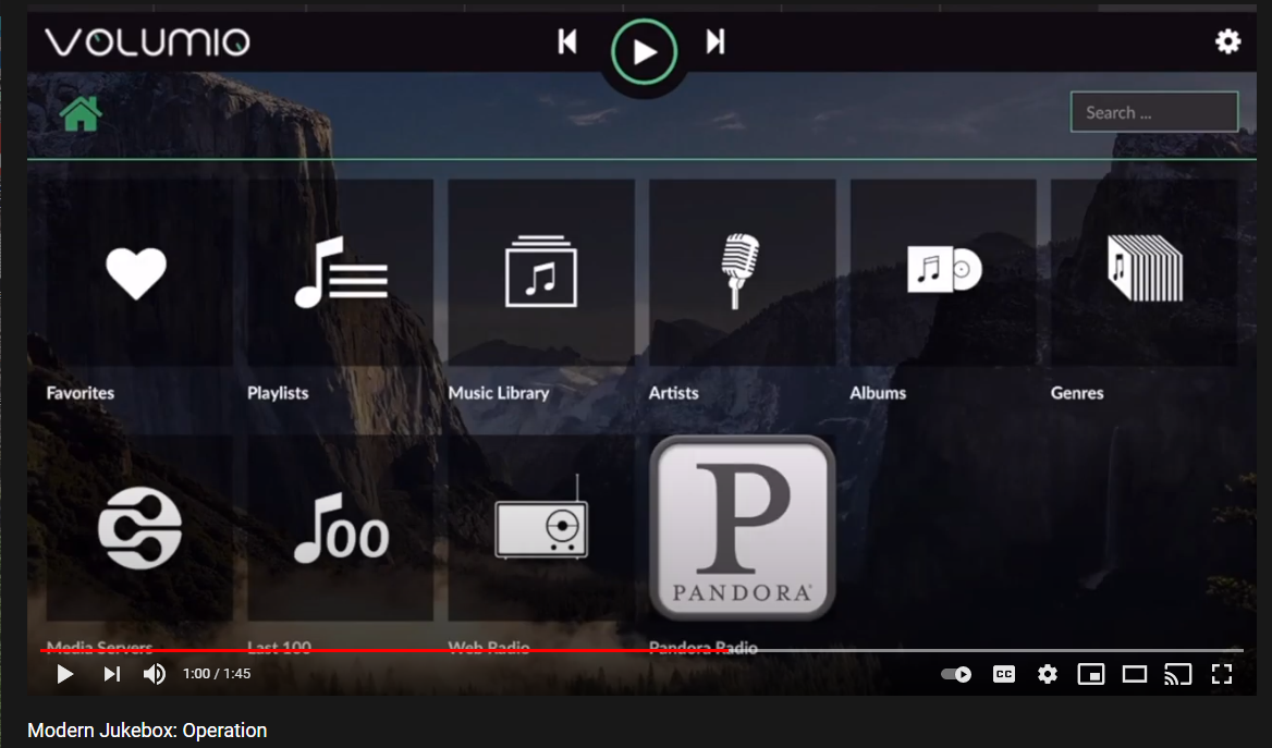
For Pandora and Spotify (paid subscription required), go to Settings/Plugins/Music Services. You can connect to Volumio from AirPlay with the Apple Music player.
Update September 20, 2021:
Raimund Trierscheid made a version of the Modern Jukebox, with improvements! Raimund added 5mm wood panels to the sides of the case to hold the heavy speakers and improve the sound.
Here are some photos:
代码
Modern-Jukebox on github
https://github.com/thisoldgeek/Modern-Jukebox定制零件和外壳
Fusion 360 design modern_jukebox_r1_v2_dccOE3MSIQ.f3d制造工艺