

操纵杆控制鼠标
组件和用品
 |
| × | 1 | |||
| × | 1 |
应用和在线服务
 |
| |||
|
关于这个项目
作为使用鼠标或触控板跟踪计算机光标的替代方法,我在操纵杆的帮助下制作了相同的应用程序。摇杆可以在任意方向(x轴和Y轴)移动光标,也可以通过内置的摇杆开关实现点击功能。
基础-
操纵杆简单地由 2 个在 x 和 y 方向对齐的电位器组成。 arduino从摇杆读取0到1023范围内的模拟值。因此,当摇杆处于默认(中心)位置时,模拟值也接近500(0到1023之间)。
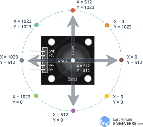
arduino 草图被编程为当操纵杆远离中心时,然后根据位置打印从 - 敏感度到 + 敏感度值(默认值设置为 10)范围内的值。所以,当操纵杆移动到一个极端位置时,arduino 打印值 10,如果操纵杆移动到另一个极端位置,则打印 -10。
要打印 x 和 y 方向的单独值,我们将在 x 和 y 方向值之间使用“:”。示例:
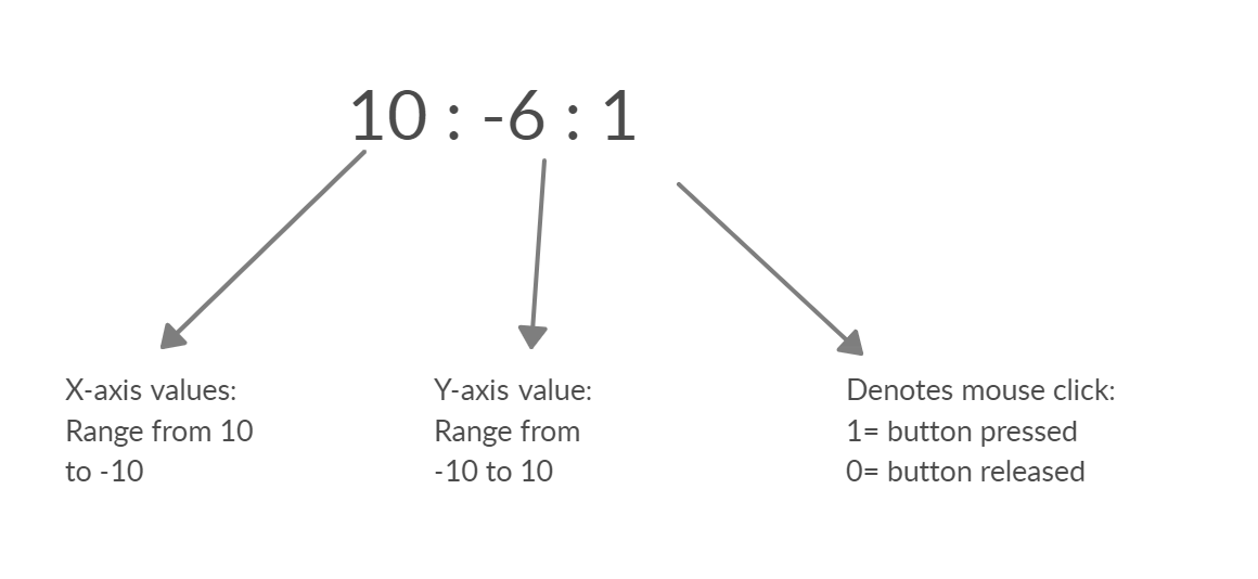
操纵杆按钮(SW)的状态在 x 和 y 值之后打印在串行监视器上(1/0)。
为了让笔记本电脑/电脑识别这些值,我们需要 python 的 pyautogui 模块。
Python编程
(2020 年 11 月 12 日编辑 - 将库从“pyautogui”更改为“鼠标”)
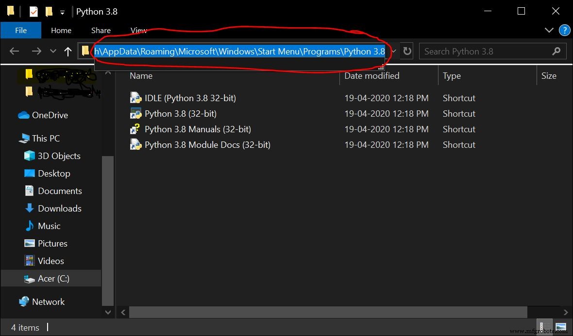
用户必须在他们的笔记本电脑/计算机上安装 python 3。可以从这里下载。
安装完成后,复制python文件所在路径。
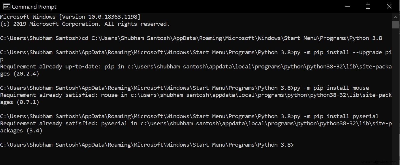
以下步骤将在命令提示符下执行。打开命令提示符并输入以下内容-
1. cd <粘贴python文件的路径>
2. py -m pip install --upgrade pip
3. py -m pip install mouse
4. py -m pip install pyserial
鼠标 模块用于执行鼠标操作和pyserial 模块用于从 arduino 发送/接收数据。我已经安装了必要的模块,所以我得到了这个
使python程序读取Arduino打印的数据并识别x 和 y 方向值以及开关(SW)的状态。
从鼠标函数mouse.get_position()获取光标的当前坐标 它以像素的形式提供光标的 X 和 Y 坐标。
当摇杆移动时,arduino 提供的模拟值与当前光标位置相加,使光标向所需方向移动。
要在给定方向移动光标,函数 mouse.move(X+x,Y+y) 满足这个目的。
其中 X 和 Y 是当前光标的位置,x 和 y 是 arduino 提供的增量/减量位置。
示例:mouse.moveTo(100,150) 将光标移动到 x 轴 100 像素和 y 轴 150 像素。
根据软件状态进行点击操作,mouse.click(button="left") 使用。
最终执行
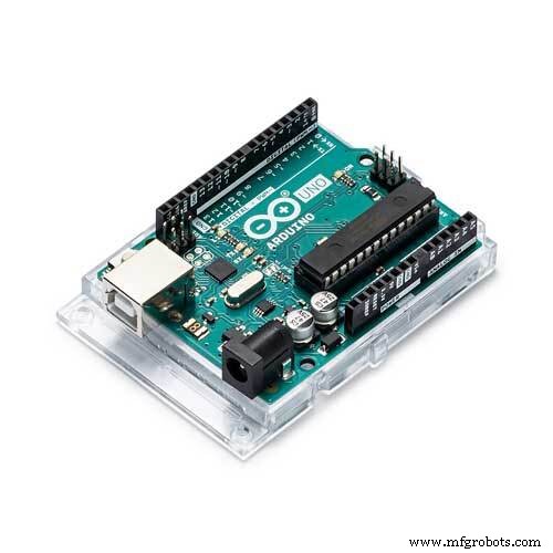
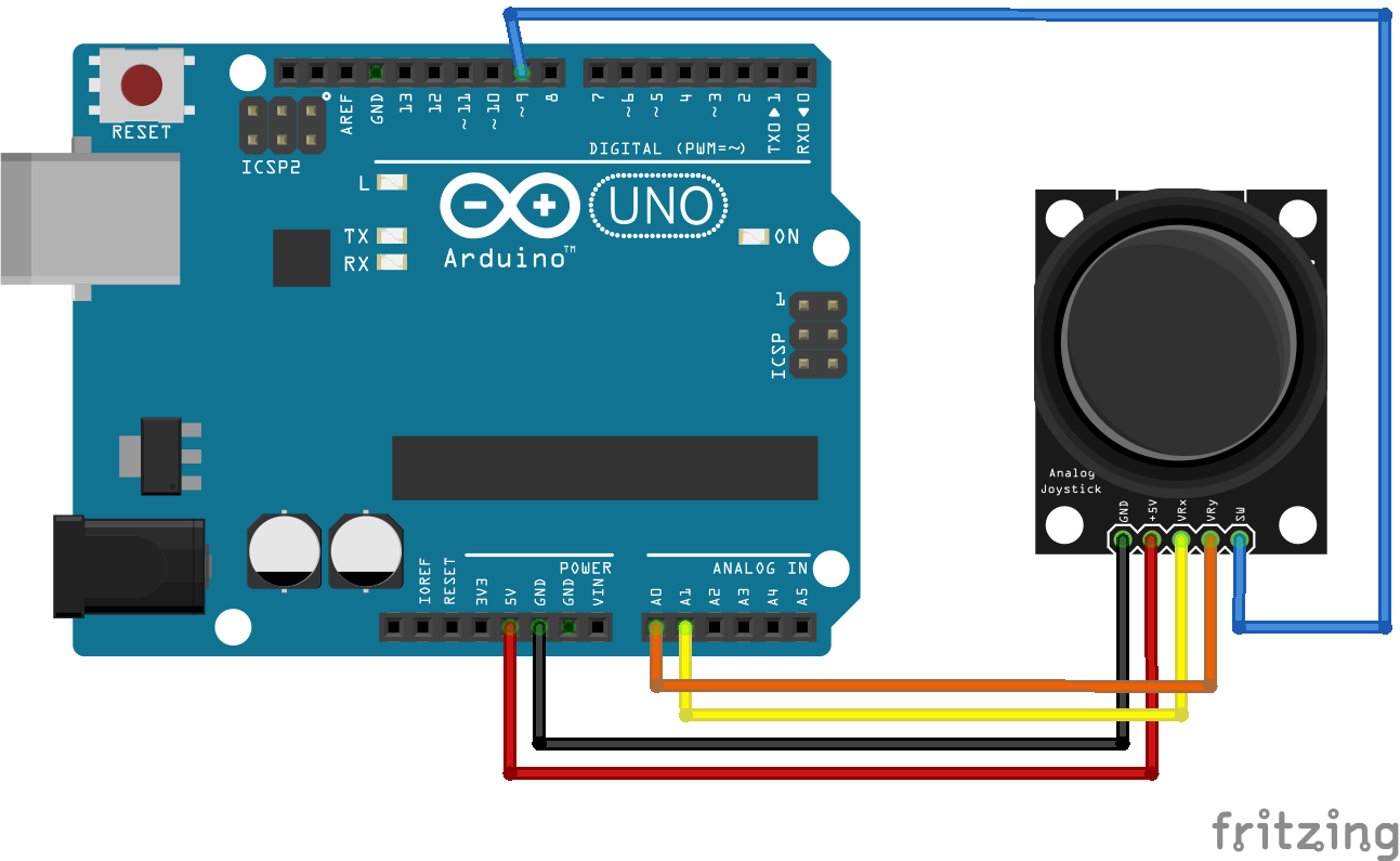
将 arduino 草图(如下所示)上传到您的 arduino UNO 并将操纵杆连接到示意图中给出的 arduino 引脚。
确保您的计算机/笔记本电脑上安装了鼠标和 pyserial 后,执行以下步骤。
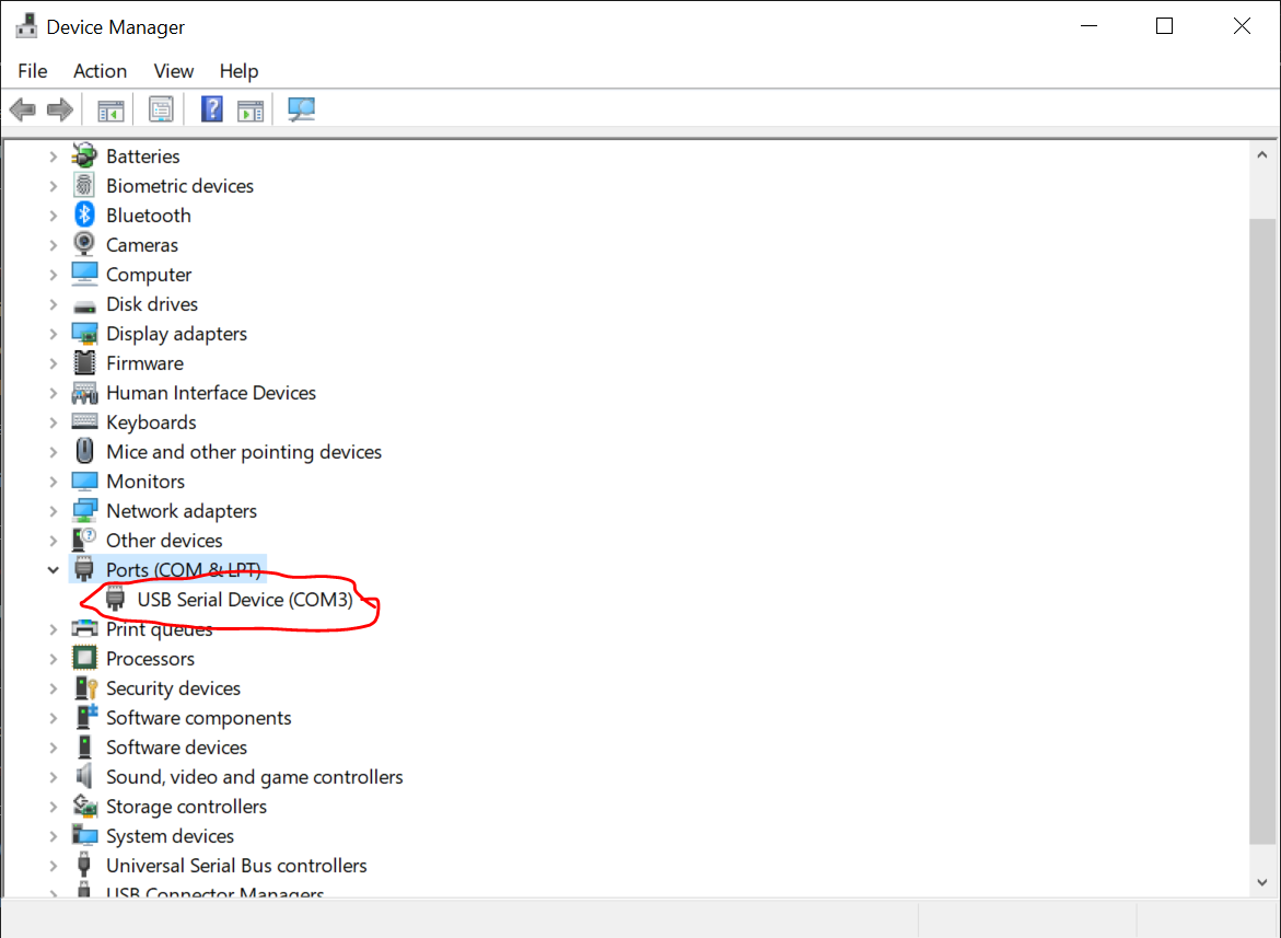
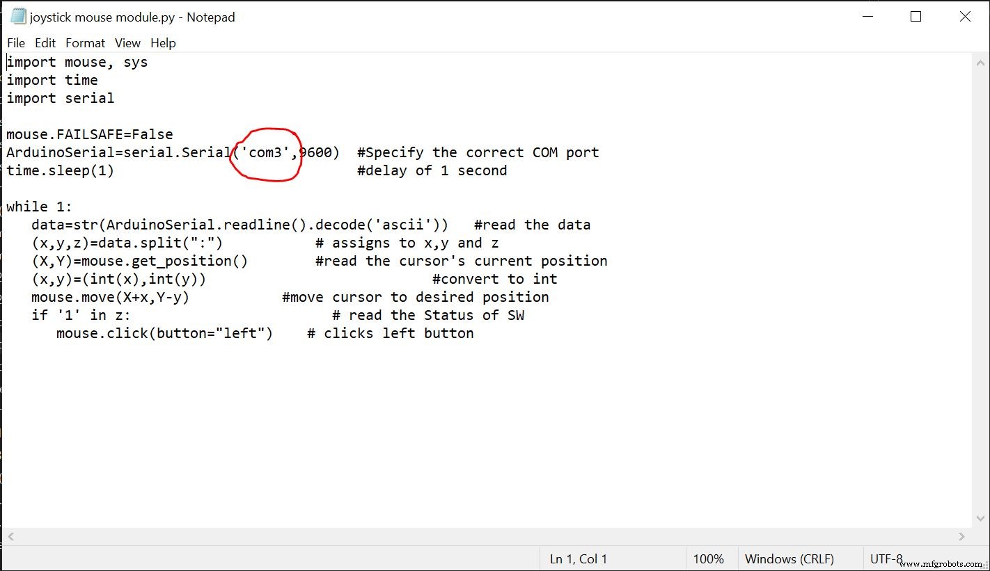
1.将python草图复制到记事本文件中。指定 arduino 的正确 COM 端口。从设备管理器中,您可以获取 arduino 板所连接的 COM 端口。更改后将文件另存为“.py”。
2.打开python的IDLE(python GUI)并从中打开记事本文件。
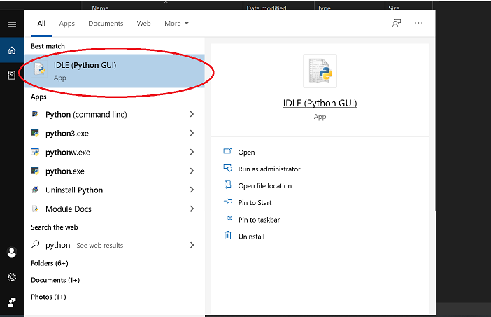
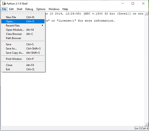
3. 运行模块。
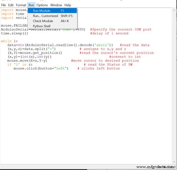
然后您将被引导回图 4 中的屏幕
如果您发现任何错误,请重新启动 IDLE 并检查您是否提到了正确的 arduino COM 端口。
如果没有错误,则移动操纵杆,您将看到光标的移动。
代码
- Arduino 代码
- Python 代码
Arduino 代码Arduino
//////////////////////////////// 操纵杆控制鼠标////// 舒巴姆·桑托什/ /////////////////////////////////void setup() { Serial.begin(9600); pinMode(9,输入); // SW pin digitalWrite(9,HIGH);}int prev_state=0; // switchvoid loop() 的前一个状态 { int z=0,xpos=0,ypos=0; int x=analogRead(A0); int y=analogRead(A1);整数灵敏度=10; // 您可以根据自己的舒适度调整灵敏度 if(x>=550) // 向上移动时 xpos=map(x,550,1023,0,sensitive); if(x<=450) // 当向下移动时 xpos=map(x,450,0,0,-sensitive); if(y>=550) // 当向右移动时 ypos=map(y,550,1023,0,sensitive); if(y<=450) // 当向左移动时 ypos=map(y,450,0,0,-sensitive); int curr_state=digitalRead(9); if(curr_state==1 &&prev_state==0) // 当按下 SW 时 z=1;否则 z=0; if(xpos!=0 or ypos!=0 or z==1) // 仅在操纵杆移动时打印 { Serial.print(xpos); // 打印数据并以“:”分隔 Serial.print(":"); Serial.print(ypos); Serial.print(":"); Serial.println(z); } prev_state=curr_state;延迟(10); // 正常操作} Python 代码Python
# Joystick 控制的鼠标# By Shubham Santosh# lastedited 12/11/2020import mouse, sysimport time import serialmouse.FAILSAFE=FalseArduinoSerial=serial.Serial('com3',9600) #指定正确的COM端口time.sleep(1 ) #delay of 1 secondwhile 1:data=str(ArduinoSerial.readline().decode('ascii')) #读取数据 (x,y,z)=data.split(":") # 赋值给 x, y and z (X,Y)=mouse.get_position() #读取光标当前位置(x,y)=(int(x),int(y)) #转换为int mouse.move(X+x,Yy) ) #move cursor to 期望位置 if '1' in z:# read the Status of SW mouse.click(button="left") # clicks left button 示意图
制造工艺