

连铸钢中的夹杂物及其检测
连铸钢中的夹杂物及其检测
钢的连铸具有节能、高产、操作灵活、铸件质量具有竞争力等先天优势,是世界范围内钢铁生产的重要工艺。随着连铸成为钢铁生产的主要路线,人们越来越重视通过连铸技术提高钢铁生产的质量和降低成本方面。当今最严格的质量要求之一是钢材的清洁度。钢的高清洁度要求在连铸过程中严格控制非金属夹杂物或简单的夹杂物。残留在最终产品中的夹杂物会损害钢材性能并降低其质量。
连铸结晶器中的夹杂物很难去除,因为钢水变成固态,夹杂物浮出的机会较少。钢产品中夹杂物的去除和夹杂物的最终分布高度依赖于夹杂物的性质、夹杂物在钢液中的迁移以及夹杂物与凝固壳的相互作用。因此,了解夹杂物的截留情况及其在最终产品中的最终分布情况,对于控制钢材的清洁度和质量具有重要意义。
热轧和/或冷轧钢的表面质量问题一直是人们关注的重要问题之一,因为它直接关系到钢材的质量和价格。轧钢的表面质量也受到连铸和再加热过程的影响,因为夹杂物是轧钢表面裂纹产生的主要原因之一。有人尝试通过基于热力学计算改变夹杂物成分和形态来提高钢的表面质量。但这些尝试似乎还不足以彻底解决表面质量问题。
钢中夹杂物的评价具有重要意义,包括(i)探索夹杂物的总量、形态、尺寸分布和空间分布,以及(ii)确定其化学成分。
对优质钢材的需求不断提高,使炼钢人员越来越意识到对钢材洁净度的要求。夹杂物是铸钢中的一个重要问题,可导致其过度修复或拒收。轧钢产品中的一些缺陷可能与夹杂物有关。钢的力学行为在很大程度上受夹杂物和析出物的体积分数、尺寸、分布、成分和形态的控制,这些夹杂物和析出物充当应力提升物。夹杂物尺寸分布尤为重要,因为大的宏观夹杂物对机械性能最有害。有时灾难性缺陷是由完整钢炉中的单个大夹杂物引起的。虽然大夹杂物的数量远远超过小夹杂物,但它们的总体积分数可能很大。
增加氧化物或硫化物夹杂物的数量会显着降低延展性。当夹杂物存在于高强度低延展性合金钢中时,断裂韧性也会降低。在反映缓慢、快速或循环应变率的测试(例如蠕变、冲击和疲劳测试)中观察到夹杂物的类似性能退化。此外,夹杂物会导致空隙,从而导致裂纹。大的外来夹杂物会导致表面质量差、抛光性差、耐腐蚀性能下降,在特殊情况下还会产生渣线和叠层。
夹杂物还降低了对“氢致裂纹”(HIC)的抵抗力。钢中大部分疲劳问题的根源是硬而脆的氧化物,尤其是尺寸超过 30 微米的大氧化铝 (Al2O3) 颗粒。尽管夹杂物的凝固形态在铸钢中很重要,但锻钢产品中夹杂物的形态很大程度上受其在钢加工过程中的力学行为控制,即它们相对于钢基体是“硬”还是“软”。轧制过程中不同类型夹杂物的行为及其变形示意图如图1所示。
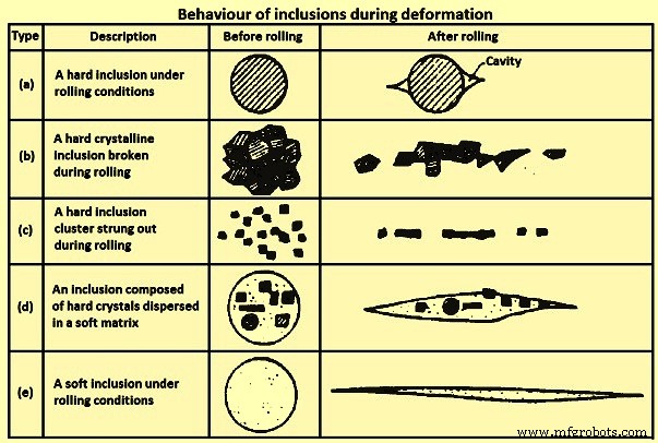
图1 夹杂物在变形过程中的行为
图 1 中 (b) 和 (c) 类型的“纵梁”形成增加了机械性能的方向性,因此尤其对韧性和延展性产生不利影响。韧性和延展性最差的夹杂物,特别是在平板轧材的厚度方向特性中,是那些随基体变形的夹杂物,如图 1 中的 (d)。为了避免这些问题,有害夹杂物的尺寸和频率应精心控制。尤其是在临界尺寸以上的铸钢中不得出现夹杂物。
夹杂物的表征是确保钢洁净的最重要方面之一。夹杂物是钢中存在的一种缺陷,会严重影响钢的抛光性、延展性和疲劳强度等性能。因此,为了生产高性能钢,需要控制夹杂物。主要夹杂物是在钢包钢处理过程中形成的。其中大部分被去除到钢包渣或炉衬上。然而,其余的夹杂物仍有待通过连续的工艺阶段去除,另外在铸造和凝固过程中会形成新的夹杂物。
由于夹杂物的数量随着尺寸的增加而减少,不同尺寸的区间会带来不同的问题。就抛光性而言,大量的小夹杂物比大但同时更稀有的夹杂物更有害,因为它们更频繁地出现。另一方面,在低应力水平下,可能导致钢产品寿命期内失效的临界裂纹最有可能在非常大的夹杂物处生长。这些夹杂物很少见,很难正确估计它们的出现密度。在中等疲劳应力水平下,中等尺寸的夹杂物与表面缺陷作为裂纹萌生点竞争。
钢中的夹杂物可以内生(本地)或外生形成。内源性夹杂物是钢中的合金元素与溶解的气体(如氧气)反应在铸钢中形成固体夹杂物的结果。夹杂物可以在脱氧、再氧化或固化过程中由降低的气体物质在固态下的溶解度形成。外源性夹杂物来自钢水以外的来源,例如夹渣或耐火材料损坏。
内生夹杂物
内源性夹杂物是钢在冷却凝固过程中的脱氧产物或析出的夹杂物。
脱氧产品 – 低碳铝镇静(LCAK)钢中的氧化铝夹杂物和硅镇静钢中的二氧化硅(SiO2)夹杂物是溶解氧与添加的铝和硅脱氧剂反应生成的典型脱氧夹杂物。氧化铝夹杂物在高氧环境中形成时呈树枝状。来自脱氧或再氧化的簇状氧化铝夹杂物是铝镇静钢的典型特征。氧化铝夹杂物由于界面能高,容易通过碰撞和聚集形成三维团簇。簇中的单个夹杂物的直径可以是 1 微米到 5 微米。在与其他颗粒碰撞、破碎或聚集之前,它们可以呈花盘状,或(聚集)多面体包裹体。或者,珊瑚状氧化铝夹杂物被认为是由原始树枝状或簇状氧化铝夹杂物的“奥斯特瓦尔德熟化”产生的。由于在钢水中处于液态或玻璃态,二氧化硅夹杂物通常呈球形。二氧化硅也可以聚集成簇。
沉淀夹杂物 – 这些夹杂物在钢的冷却和凝固过程中形成。在冷却过程中,液体中溶解的氧/氮/硫的浓度会升高,而这些元素的溶解度会降低。因此夹杂物如氧化铝、二氧化硅、氮化铝 (AlN) 和硫化物沉淀。硫化物在凝固过程中在枝晶间形成,并经常在钢水中已经存在的氧化物上成核。这些夹杂物通常很小(小于 10 微米)。
外来夹杂物
外源性夹杂物主要来自钢液与周围环境的偶然化学反应(再氧化)和机械相互作用(夹渣和内衬耐火材料的侵蚀)。在加工过程中,会产生颤振,造成加工断面表面出现凹坑、划痕,经常出现折断,刀具磨损过大。
外源性夹杂物总是与实践相关,其大小和化学成分经常导致对其来源的识别,其来源主要是再氧化、夹渣、内衬侵蚀和化学反应。这些夹杂物具有以下特点。
大号 – 耐火侵蚀的外源夹杂物通常比夹渣大。
复合成分/多相性质 – 外源性夹杂物是由以下现象引起的:(i) 由于钢液与二氧化硅、FeO 和 MnO 之间的反应,在炉渣和内衬耐火材料中生成的氧化铝夹杂物可以留在其表面,(ii) 随着外源性夹杂物的移动,由于它们的大尺寸,它们可以在其表面捕获脱氧夹杂物,例如氧化铝,(iii)外源夹杂物在钢水运动过程中作为异质核位点,用于新夹杂物的析出,以及(iv)熔渣或再氧化夹杂物可以与内衬耐火材料发生反应或将其他材料移入钢液中。
形状 – 外源夹杂物通常具有不规则的形状,如果不是球形,则来自夹渣或脱氧产物二氧化硅。球形外源夹杂物一般较大(大于50微米)且多为多相,而球形脱氧夹杂物一般较小且为单相。
数量 – 与小夹杂物相比,外源夹杂物数量较少。
分布 – 外源性夹杂物在钢中呈零星分布,作为小夹杂物分散不好。由于它们通常在浇注和凝固过程中被困在钢中,因此它们的发生是偶然的和零星的。另一方面,它们很容易浮出,因此只集中在钢型材中凝固最快的区域或在某种程度上阻碍它们通过浮选逸出的区域。因此,这些夹杂物经常出现在地表附近。
对钢材性能的影响 – 与小夹杂物相比,外源夹杂物体积大,对钢性能的危害更大。
超越外源夹杂物来源的一个问题是,为什么如此大的夹杂物一旦存在于钢中就不会迅速浮出。可能的原因可能是 (i) 炼钢过程中的晚期形成、转移或冶金容器中的腐蚀,使它们在进入铸造机模具之前没有足够的时间上升,(ii) 缺乏足够的过热度,(iii) 凝固期间的流体流动导致模渣夹带,或 (iv) 漂浮的夹杂物在完全进入炉渣之前重新夹带。
再氧化产生的外源性夹杂物 – 在钢中发现的再氧化中最常见的大型宏观夹杂物是氧化铝簇。空气是最常见的再氧化源,可能发生 (i) 由于强烈的湍流,中间包中的钢水在浇注开始时与顶部表面的空气混合,流动液体表面的氧化膜折叠进入液体中,形成薄弱的氧化物颗粒平面,(ii) 空气在钢包和中间包之间以及中间包和结晶器之间的连接处被吸入钢水,以及 (iii) 空气从钢包中渗入钢中浇注过程中钢包、中间包和模具中钢的顶面。
在这种再氧化过程中,铝、钙、硅等脱氧元素被优先氧化,其产物发展为夹杂物,通常比脱氧夹杂物大一到两个数量级。防止这种再氧化的解决方案是限制空气在铸造过程中的暴露。这可以通过 (i) 在钢包和中间包之间以及中间包和结晶器之间的连接处使用钢环歧管或多孔耐火环覆盖惰性气体幕来完成,(ii) 通过将一些氩气吹扫到浇注前的中间包,浇注时进入中间包表面,(iii)通过控制钢包中的氩气注入来避免形成眼。
另一个再氧化源是炉渣和内衬耐火材料。通过这种再氧化机制,钢中的夹杂物通过 SiO2 / FeO / MnO + [Al] =[Si] / [Fe] / [Mn] + Al2O3 反应在靠近炉渣或炉衬界面处生长。这导致具有可变成分的较大氧化铝夹杂物。这种现象进一步以不同的方式影响外源夹杂物,即(i)这种反应会侵蚀和不均匀的衬里表面,这会改变衬里壁附近的流体流动模式,并可能导致衬里进一步加速破裂,以及(ii)a大的外生夹杂物破碎衬里或夹带的夹杂物可以夹带小夹杂物,如脱氧产物,也可作为新析出物的异质核,使外生夹杂物的成分复杂化。
为了防止炉渣和内衬耐火材料的再氧化,保持低的SiO2、FeO和MnO含量非常重要。据报道,游离二氧化硅含量低的高铝或氧化锆砖更适合使用。
夹渣产生的外源性夹杂物 – 任何炼钢操作或钢水转移都涉及熔渣和金属的湍流混合,尤其是在容器之间转移的过程中。这会产生悬浮在钢中的矿渣颗粒。夹渣尺寸为 10 微米至 300 微米,含有大量 CaO(石灰)或 MgO(氧化镁),在钢水温度下通常为液态,因此呈球形。使用“H”形中间包并通过两个钢包浇注可减少钢包更换期间的夹渣。影响连铸过程中夹渣进入钢水的原因包括(i)在从钢包到中间包和从中间包到结晶器的转移操作过程中,特别是对于敞开浇注,在低水平的钢水顶面产生涡流可以通过多种方式避免钢水的流失,例如在涡流开始之前关闭浇注,(ii)在顶部表面的乳化和夹渣,尤其是在高于临界气体流速的气体搅拌下,(iii)弯月面处的湍流(iv)渣的界面张力和渣粘度等特性。
例如,由于 (i) 弯液面处的湍流(图 2A)、(ii) 涡流(图 2C)、(iii) 气泡从钢中移动到熔渣引起的乳化,脱模粉可能被夹带在钢液中[图 2B 和 2D),(iv) 由于压力差 (2E) 沿喷嘴壁吸入,(v) 从表面剪切熔渣的高速流动 (2A),以及 (vi) 液位波动(图 2B) .
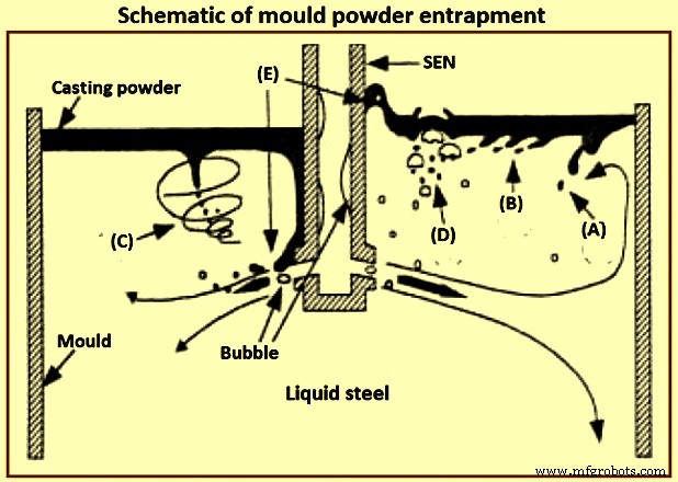
图 2 模具粉末截留示意图
钢与液态铸粉之间的界面张力决定了钢弯月面的高度,以及助熔剂夹带的难易程度。具体而言,对于与纯铁接触的石灰-二氧化硅-氧化铝炉渣,每米 (N/m) 的界面张力为 1.4 牛顿,从而产生大约 8 毫米的弯液面高度。通过表面活性物质(例如硫)或通过界面交换反应(例如钢中的铝被炉渣中的氧化铁氧化),界面张力降低到低值。与化学反应相关的非常低的界面张力可以通过马兰戈尼效应在界面处提供自发湍流。这种湍流会在界面处形成乳液,从而在钢中产生不希望的渣珠。
耐火衬里侵蚀/腐蚀产生的外源夹杂物 – 耐火材料的侵蚀,包括井块砂、松散的污垢、破碎的耐火砖砌体和陶瓷内衬颗粒,是大外源夹杂物的常见来源,这些夹杂物通常是固体,与钢包和中间包本身的材料有关。这些通常是大而不规则形状的材料。 外源性夹杂物可作为氧化铝异相形核的场所, 或与其他土著内含物聚合。耐火侵蚀产物或机械引入的夹杂物的出现会完全损害原本非常干净的钢的质量。
在一些研究侵蚀过程的研究中,据报道,“釉面耐火材料”和“砖表面的反应层”是由 1,550 摄氏度至 1,600 摄氏度的钢水形成的。内衬表面也可以释放到钢液中。
内衬腐蚀通常发生在湍流区域,特别是在再氧化、高浇注温度和化学反应结合时。下面介绍对内衬侵蚀影响较大的参数。
一些钢种具有很强的腐蚀性(例如高锰和几乎不被杀死且具有高溶解氧含量的钢种)并且会腐蚀衬砖。
再氧化反应,例如钢水中溶解的铝会减少内衬耐火材料中的二氧化硅,生成氧化铁基夹杂物,这些夹杂物非常活泼并润湿内衬材料,导致高流体湍流区域内衬耐火材料的腐蚀。
砖的成分和质量对钢材质量有相当大的影响。其中一家工厂采用了三种材料(高氧化铝、Al2O3-SiC-C 和 MgO-C,磨损率分别为 1 毫米/热、0.34 毫米/热、0.16 毫米/热)。渣线,耐火材料容易被中间包熔剂和熔渣侵蚀,镁碳砖在三者中表现出最高的耐久性。氧化锰优先侵蚀耐火材料的含二氧化硅部分。非常高纯度的氧化铝和氧化锆晶粒可以承受氧化锰的侵蚀。
高锰钢的快速耐火侵蚀可以通过以下方式来限制:(i) 使用非常高纯度的氧化铝或氧化锆耐火材料,(ii) 通过使用强脱氧剂(如铝或钙)完全杀死钢并防止空气吸收来最大限度地减少氧气。二氧化硅基中间包内衬比氧化镁基喷涂内衬差。高铝耐火材料被认为是最有前途的。将氧化钙加入到喷嘴耐火材料中有助于液化壁上的氧化铝夹杂物,只要 CaO 扩散到界面的速度足够快并且喷嘴腐蚀不成问题。可以通过控制喷嘴耐火材料成分(例如避免钠、钾和硅杂质)或用纯氧化铝、氮化硼或其他耐腐蚀材料涂覆喷嘴壁来对抗喷嘴腐蚀。应选择护罩壁表面的耐火材料,以尽量减少与钢的反应,从而产生夹杂物和堵塞。
钢水速度过快会影响沿中间包内壁的内衬腐蚀,例如入口区。垫可以用来防止中间包底部的侵蚀,以及控制流动模式。有人认为,超过 1 米/秒的钢水速度对于侵蚀是危险的。
接触或填充时间过长以及高温会恶化腐蚀问题。在钢包中长时间保持期间,较大的夹杂物会漂浮到钢包渣中。然而,钢与钢包内衬接触的时间越长,钢包腐蚀产物的趋势就越大。解决方案基于为给定钢种开发高度稳定的耐火材料、为高流动区域开发致密耐磨耐火材料嵌件以及防止再氧化。
化学反应产生的外源性夹杂物 – 钙处理不当时,化学反应会因夹杂物改性而产生氧化物。确定这些夹杂物的来源并不总是容易的,例如,含有氧化钙的夹杂物也可能来自夹带的炉渣。
夹杂物聚集和堵塞 – 在表面张力效应的帮助下,任何表面都可能发生固体夹杂物的聚集,包括耐火材料和气泡表面。液态钢中氧化铝的高接触角(134 度至 146 度)促使夹杂物自身附着在耐火材料上,以尽量减少与钢的接触。 1,530 摄氏度的高温使氧化铝能够发生烧结。较大的接触角和较大的夹杂物尺寸有利于夹杂物的团聚。由于碰撞和结块,钢中的夹杂物往往会随着时间和温度的升高而增长。夹杂物在铸锭中的碰撞、团聚和凝聚生长一直是各种研究的主题,其中报道了从添加脱氧剂开始的夹杂物成核以及从纳米尺寸到微米尺寸的碰撞和扩散生长的数值模拟。
氧化铝烧结成簇的基本原理需要进一步研究,尽管一些研究使用分形理论来描述簇形态(特征)。内衬耐火材料表面夹杂物结块最明显的例子是钢水连铸过程中的水口堵塞。
流体流动和凝固对夹杂物的影响 – 钢连铸中的夹杂物分布受钢液流动、传热和凝固的影响。夹杂物截留的一个流行指标是凝固前沿的临界前进速度,它受夹杂物形状、密度、表面能、热导率、冷却速度(凝固速率)和凝固前沿突出条件等几个参数的影响。据报道,诱捕是由阻力和界面力(范德华力)控制的。有人提出,凝固速度越快,被夹住的可能性就越高。夹带的可能性随着凝固时间的增加、偏析的减少、凝固前沿的小突起的减少而降低。枝晶臂间距对夹杂物的截留影响很大,并与推挤、吞噬现象有关;或诱捕。
连续铸造操作、夹杂物和洁净钢
连铸操作控制钢的清洁度。对夹杂物去除的系统研究发现,钢包处理使夹杂物降低约 65% 至 75%,中间包去除夹杂物约 20% 至 25%,尽管有时会发生再氧化,模具去除夹杂物约 5%到 10%。中间包操作对钢的清洁度影响很大。中间包操作中影响钢的清洁度的重要因素是中间包深度和容量、浇注过渡、中间包内衬耐火材料、中间包熔剂、氩气搅拌和中间包流量控制。
顶渣 – 钢包和中间包中的顶部熔渣具有多种功能,例如 (i) 对钢水进行热绝缘(防止过度热损失)和化学绝缘(防止空气夹带和再氧化),以及 (ii) 吸收夹杂物提供额外的钢铁精炼。一种常见的中间包助熔剂是烧焦的稻壳,它价格低廉,是一种良好的绝缘体,并且可以提供良好的覆盖而不会结壳。然而,稻壳中的二氧化硅含量很高(约 80 % SiO2),可以将其还原为夹杂物的来源。它们也非常多尘,并且碳含量高(约 10 % C),会导致超低碳钢受到污染。
在 LCAK 钢的精炼过程中,碱性熔剂(CaO-Al2O3-SiO2 基,二氧化硅含量低于 10%)理论上比稻壳好得多,并且与中间包中的低氧有关。例如,在一项研究中,总氧气已从 25 ppm(百万分之几)和 50 ppm 的范围降低到 19 ppm 和 35 ppm 的范围,助焊剂的碱度从 0.83 增加到 11。据报道,钢厂使用碱性熔剂,模具中的总氧含量较低,钢材缺陷有所减少。然而,更可能的是,基本焊剂是无效的,因为它容易在表面形成结壳,因为它具有更快的熔化速度和高结晶温度。这种结壳导致在浇注过程中钢包长水口周围形成一个开放的无渣眼,这不仅为再氧化提供了过多的区域,而且还给工作平台上的操作员带来了显着的辐射热损失和不适。此外,碱性焊剂通常具有较低的粘度。因此,它们更容易被夹带。为了避免这些问题,一家钢铁厂使用了两层助焊剂,底部的低熔点基础助焊剂吸收夹杂物,顶层稻壳基助焊剂提供绝缘。这已将总氧气从 22.5 ppm 降低到 16.5 ppm。
中间包深度、容量和流量控制装置 – 中间包流动模式旨在增加钢水停留时间,防止“短路”并促进夹杂物的去除。中间包流量受其几何形状、液位、入口(护罩)设计和流量控制装置(如冲击垫、堰、坝、挡板和过滤器)控制。大容量的深中间包增加了钢水和颗粒的停留时间,从而促进了夹杂物的去除。较深的中间包也能阻止涡流的形成,从而在夹渣成为问题之前有更多的时间进行钢包过渡。在过去的 20 年里,LCAK 钢的中间包尺寸在全球范围内逐渐增加,对于板坯连铸机,通常达到 60 吨至 80 吨,深度约为 1.8 米英寸。
如果正确对齐,并且可能与堰和坝一起使用,倾倒垫可以提高钢的清洁度,尤其是在钢包更换期间。例如,在其中一家钢铁厂添加浇注垫已将钢包过渡期间的氧化铝从 48 ppm 降低到 15 ppm。在另一家钢铁厂,总氧气已从 26 ppm(使用圆顶垫)降至 22 ppm(使用轮毂盖垫)。在另一家钢铁厂,通过在大坝上打了 77 个孔,使其充当部分过滤器,钢的清洁度得到了改善。在另一家钢厂,一种由挡板与初始中间包盖相结合的类似技术已将稳态铸造期间中间包中的平均总氧从 39 +/- 8 ppm 降低到 24 +/- 5 ppm。
陶瓷过滤器和 CaO 过滤器在去除夹杂物方面非常有效。然而,它们的成本和堵塞前的有效运行时间通常使它们的使用令人望而却步。将惰性气体从中间包底部注入中间包,可以改善钢液的混合,促进夹杂物的碰撞和去除。在其中一家钢铁厂,通过应用这项技术,中间包中的总氧气量已成功降至 16 ppm。然而,这种技术的危险在于,任何从中间包中逸出并被夹在铸流中的夹杂物气泡都会导致严重的缺陷。据报道,采用该工艺后,中间包钢的氧化物面积分数(0.001 %)比未采用该工艺的钢降低了25 %。
投射过渡 – 浇注过渡发生在浇注程序的开始、钢包更换和水口更换期间以及浇注结束时。这些转变是造成大部分清洁度缺陷的原因。夹杂物在过渡过程中经常产生,并且可以持续很长时间,从而污染大量钢材。已发现在第一炉开始时的条子缺陷指数比第一炉中间高5倍,是连续加热的15倍以上。在这些不稳定的铸造期间,更容易发生夹渣和空气吸收,从而引发再氧化问题。 “自动打开”钢包无需喷枪即可自行打开。切割需要移除护罩,这允许发生再氧化,特别是在铸件的前 650 毫米到 1,200 毫米期间。枪口开炉的总氧含量比自开炉高约 10 ppm。钢包开口砂的仔细填塞有助于实现钢包的自开。由于二氧化硅含量高,钢包砂也是再氧化的来源。
钢包过渡期间的一项改进是停止液体流入模具,直到中间包被填充,并通过塞子鼓泡气体以促进夹杂物浮选。另一个改进是打开带有浸没式罩盖的新钢包。通过这项措施,其中一家钢铁厂的总氧气量从 41 +/- 14 ppm 降低到 31 +/- 16 ppm,并且整个生产过程的质量更加稳定。
例如,在一家钢铁厂,过渡期间中间包中的总氧为 50 ppm 至 70 ppm,而稳态时仅为 25 ppm 至 50 ppm。在其他钢铁厂,差异仅为 3 ppm。 One of the steel plants has reported transitions to have total oxygen only 19.2 ppm relative to 16 ppm at steady state while another steel plant has reported total oxygen of 27 +/- 5 ppm during transitions and 24 +/- 5 ppm during steady casting. At one other steel plant, the nitrogen pickup in tundish is 5 ppm to 12 ppm during the start period of the teeming which decreases to 0 ppm to 2 ppm after around 12 minute of teeming (steady casting state).
Near the end of the teeming of a ladle, ladle slag can enter the tundish, due to the vortex formed in the liquid steel near the ladle exit. This phenomenon needs some steel to be kept in the ladle upon closing (e.g. a four ton of ‘heel’). In addition, the tundish depth drops after ladle close, which disrupts normal tundish flow and can produce slag vortexing, slag entrainment, and increased total oxygen in the mould.
Shrouding, argon protection, and sealing – Steel shrouding from ladle to the mould includes ladle slide gate shrouding, ladle collector nozzle, ladle shroud connection, tundish well block, and top plate of the tundish slide gate. Shroud design variations are of great importance in the operations of the tundish-to-mould transfer of liquid steel. Use of an optimized shrouding system greatly lowers reoxidation during transfer operations. For example, use of a ladle shroud has lowered nitrogen pickup from 24 ppm to 3 ppm relative to open pouring at one of the steel plant. In another steel plant, replacing the tundish pour box with a ladle shroud and dams has lowered nitrogen pickup (ladle to tundish) from 7.5 ppm to 4 ppm, and also has lowered slag entrainment during transitions. At one other steel plant, improving the shroud system from ladle to tundish has lowered the nitrogen pickup from 14 ppm to 3 ppm.
Shrouding the ladle to tundish stream at one of the steel plants has lowered the dissolved aluminum loss from 130 ppm to 70 ppm and has lowered the total oxygen increase by 12 ppm. When pouring without shrouds, which is common in billet casting, the turbulence of the casting stream is very important. A smooth stream entrains much less oxygen than a turbulent or ‘ropy’ stream. For the production of a smooth stream between the tundish and the mould in these operations, the metering nozzle edges are to be maintained and high speed flow in the tundish across the nozzles is to be avoided. A protective tundish cover with carefully sealed edges also helps in lowering total oxygen from 41.5 ppm to 38 ppm.
A variety of inert gas shrouding systems is now available. Total oxygen in the cast product (LCAK steel) can be lowered from 48.5 ppm to 28.5 ppm by shrouding between the ladle and the tundish, and to 23 ppm by this shrouding plus argon sealing. It is very important to carefully seal the joints in the shrouds, both to improve cleanliness and to prevent clogging. Improving the bayonet system between the ladle nozzle and ladle shroud, lowers the nitrogen pickup there from 8 ppm to less than 1 ppm. Stiffening the submerged entry nozzle (SEN) holder and increasing its maintenance has lowered the initial nitrogen pickup from 1.8 ppm to 0.3 ppm in one of the steel plants.
Inert gas can protect the steel from air reoxidation in several ways. To combat air entrainment at the beginning of a cast, the tundish can be purged with inert gas (to displace the air) prior to ladle opening, which lowers both the total oxygen and the nitrogen pickup during startup. Argon injection to pressurize the shrouds can help to prevent the liquid steel from air reoxidation through any joints or leaks. Guidelines for minimum argon gas flow to ensure positive pressure inside the nozzle are to be made. In addition, flooding the joints with argon gas ensures that any leaks aspirate inert gas and not air.
Injecting argon into the tundish stopper rod and improved sealing at one steel plant has decreased nitrogen pickup from tundish to cast product from 5 ppm to 1.8 ppm, has lowered total oxygen in the cast product from 31 ppm to 22 ppm, has decreased the size of alumina clusters in the cast product, and has decreased clogging. Elsewhere, argon injection through the stopper rod lowered the number of inclusions detected by the Mannesmann inclusion detection by analysis surfboards (MIDAS) method by 25 % to 80 %. Injection of argon gas purge through upper plate of the sliding gate has lowered the quantity of 50 micrometers to 100 micrometers sized inclusions from 3 per square centimeter to 0.6 per square centimeter, and lowered 100 micrometers to 200 micrometers macro-inclusions from 1.4 per square centimeter to 0.4 per square centimeter.
Clogging and new techniques at SEN – The nozzle is one of the few control parameters which is relatively inexpensive to change, yet has a profound influence on the flow pattern and hence on the quality of the cast product. Nozzle parameters include bore size, port angle and opening size, nozzle wall thickness, port shape (round, square, or oval), number of ports (bifurcated or multiport), nozzle bottom design (well, flat , or sloped), and submergence depth. Both too large and too small submergence depth increases problems with longitudinal cracks and transverse depressions.
One of the studies has found the occurrence of corundum (Al2O3) covering the bore surface of nozzles used to pour aluminum killed steel ingot early in 1949. Another study has found that nozzle blockage occurred with high levels aluminum (0.0036 %) and that nozzle sectioning revealed dendritic growth of alumina from the nozzle wall onto the bore. Yet another study has observed clogs of aluminum, zircon, titanium, and the rare earths.
Nozzle clogs are caused by reoxidation, or by the accumulation of solid oxides or sulphides, such as alumina and calcium sulphide (CaS) in the steel. In addition to interfering with the production process, tundish nozzle / SEN clogging is detrimental to steel cleanliness for several reasons such as (i) dislodged clogs either become trapped in the steel, or they change the flux composition, leading to defects in either case, (ii) clogs change the nozzle flow pattern and jet characteristics leaving the nozzle, which disrupt flow in the mould, leading to slag entrainment and surface defects, and (iii) clogging interferes with mould level control, as the flow control device (stopper rod or slide gate) tries to compensate for the clog.
The cure for the nozzle clog problem includes improving steel cleanliness by improving ladle practices, implementing smooth and non-reacting refractories, and controlling fluid flow though the nozzle for ensuring a smooth flow pattern. Changing from a three-plate slide gate system to a stopper rod system has reduced clogging at one of the steel plant. Several practices can be used to minimize clogging. In addition to taking general measures to minimize inclusions, clogging through refractory erosion can be countered by controlling nozzle refractory composition, (e.g. avoiding sodium, potassium, and silicon impurities), or coating the nozzle walls with pure alumina, boron nitride, or other resistant material. There are several new techniques at SEN which have reported to improve the fluid flow pattern and inclusion removal, such as (i) swirl-nozzle technique, (ii) step nozzle technique, (iii) multi-ports nozzle, and (iv) oval offset bore throttle plate.
Swirl-nozzle technique – A fixed blade placed at the upstream end of the SEN induces a swirl flow in nozzle. Centrifugal force generated by the swirling flow in the nozzle can distribute the liquid steel equally to its two spouts. Since liquid steel stream with centrifugal force has the maximum velocity in the vicinity of the wall inside the nozzle, it tends to flow out of the upper part of the spout. Hence, the velocity distribution which tends to have higher values toward the lower part of the spout with a conventional nozzle can become uniform. It has been reported that by using this swirl nozzle for the continuous casting, the defect ratio of finish products (coils) has decreases to 25 % of the conventional nozzles, and casting speed has riseby 30 %. Its cost is higher only by 20 % than the cost of the conventional and hence it is cheaper than using an ‘electro-magnetic brake’. This swirl flow pattern can also be generated by the ‘electro-magnetic stirring’ at the nozzle, which can also improve the solidification structure of the cast steel as well.
Step nozzle – The flow pattern at out-ports of conventional SEN is uneven or biased because of the sliding gate of SEN. This biased flow pattern (swirl flow at out-ports of SEN) increases the impingement of the jet, and hence worsens inclusion removal to top surface. By using inner annular steps, the biased flow in mould can be weakened. The calculation suggests that the removal fraction of 50 micrometers inclusions to the top surface of the mould is 2 % with the conventional SEN, but increases to 7 % with the use of the stepped SEN.
Oval offset bore throttle plate – In the conventional system, gate throttling results in a highly skewed and biased flow in the tundish-to-mould flow channel both upstream and downstream of the gate. These effects have considerably diminished the offset bore system. The offset gate design extracts the fluid more centrally from the tundish well nozzle. Hence, the system is less sensitive to any build-up on the walls of the well nozzle, which extends the useful life of the tundish well nozzle and hence, allowing longer tundish sequences. In practice, it has also been found that clogging within the plates of the offset bore gate is considerably reduced as compared to the conventional gate.
Multiple out-ports – It is well known that the surface velocity of the mould has a big effect on slag entrainment and top surface fluctuation. Several defects are related to the surface velocity of the mould. Thus decreasing the surface velocity is very important to improve the steel cleanliness. This task can be targeted by using multiple out-ports at SEN. Addition of a bottom hole at SEN lowers the momentum of the side jets so it is possible to get a good steel flow and meniscus condition even under high throughput which is better stabilized.
Mould and operation of continuous casting machine
The continuous casting mould region is the last refining step where inclusions either are safely removed into the top slag layer or they become entrapped into the solidifying shell to form permanent defects in the steel product. Mcpherson has used the words ‘mould metallurgy’ in 1985 to emphasize the importance of the mould to improve steel cleanliness. The mould flow pattern is very important for avoiding defects since it affects particle transport and removal to the top slag or entrapment by the solidifying shell.
Top surface control – Directing too much flow towards the top surface generates surface defects, due to transients, turbulence at the meniscus, and inclusion problems from slag entrainment. However, decreasing surface flows too much can also generate problems. These include surface defects due to the meniscus region becoming too stagnant, and a higher fraction of incoming inclusion particles being sent deep before they can be removed into the slag. Hence, a balance is to be found in order to optimize the flow parameters to avoid defects.
The most obvious source of surface defects is the capture of foreign particles into the solidifying shell at the meniscus. If the steel jet is directed too deep or has too little superheat, then the liquid surface has very little motion and becomes too cold. This can lead to freezing of the steel meniscus, which aggravates the formation of meniscus hooks. This allows inclusions and bubbles to be captured, the latter forming pinholes just beneath the surface of the cast product. As an example, decreasing surface velocity below 0.4 metre/second (m/s) has been measured to increase surface pinhole defects. For avoiding these problems, the flow pattern is to be designed to exceed a critical minimum velocity across the top surface, which is estimated to be around 0.1 m/s to 0.2 m/s.
Slag entrainment is less likely with deeper nozzle submergence and slower casting speed. For avoiding shearing slag in this manner, the surface velocity is to be kept below a critical value. This critical velocity has been measured in water – oil models as a function of viscosity and other parameters. Entrainment is more difficult for shallower slag layers, higher slag viscosity, and higher slag surface tension.
A maximum limit of the argon gas injection flow rate into the nozzle has been reported as a function of the casting speed, beyond which mould slag entrainment takes place. Increasing casting speed tends to increase transient turbulent fluctuations, and worsens the extent of flow pattern asymmetries. This in turn worsens detrimental surface turbulence and level fluctuations. Improving internal cleanliness frequently needs limiting the maximum casting speed, to avoid pencil pipe defects. Lower casting speed and avoiding variations in casting speed both reduce the rate of slivers. More precisely, it is important to lower the liquid mass flow rate in order to control the jet velocity leaving the nozzle.
Fluid flow pattern – The mould flow pattern is controlled by adjustable parameters such as nozzle geometry nozzle submergence depth, argon gas injection rate, and the application of electro-magnetic forces. It also depends on parameters which normally cannot be adjusted to accommodate the flow pattern, such as the position of the flow control device (slide gate or stopper rod), nozzle clogging, casting speed, strand width, and strand thickness. All of these parameters together form a system which is to be designed to produce an optimal flow pattern for a given operation.
Bubbles, which are injected into the nozzle and the mould, have five effects related to the control of tge steel quality. These effects are (i) helping to reduce nozzle clogging, (ii) helping influence and control the flow pattern in the mould, (iii) generating serious top surface fluctuation even emulsification if gas flow rate is too large, (iv) capturing inclusions as they flow in the liquid steel, and (v) bubbles entrapped solid oxide particles captured by solidified shell eventually lead to surface slivers or internal defects.
Normally, low gas flow tends to double-roll flow pattern, while a high argon flow rate induces single-roll flow. This phenomenon has been studied as early as in 1983. For maintaining a stable double roll flow pattern, which is frequently optimal, the argon is to be kept safely below a critical level. Excessive argon injection can generate transient variation of the jets entering the mould, introduce asymmetry in the mould cavity, and increase surface turbulence. Argon gas bubbles can also be trapped in the solidifying steel shell to form blister defects, such as pencil pipe in the finish product.
It has been observed that inclusion entrapment varies from side to side, which suggests a link with the variations in the transient flow structure of the lower recirculation zone, and the asymmetrical flow pattern (Fig 3), which can be induced by nozzle clogging, by turbulence, and by excessive argon gas injection. It is especially important to keep nearly constant the liquid steel level in the mould, powder feeding rate, casting speed, gas injection rate, slide gate opening, and nozzle position (alignment and submergence).
Electro-magnetic forces can be applied to the liquid steel in a number of ways to alter considerably the flow pattern in the strand. It has been reported that electro-magnetic stirring of outer strands can improve the steel cleanliness, lowering total oxygen in the cast product from 30 ppm to 20 ppm. Another example is the electro-magnetic brake (EMBR), which bends the jet and shortens its impingement depth, to lessen the likelihood of capture by the solidified shell deep in the strand.
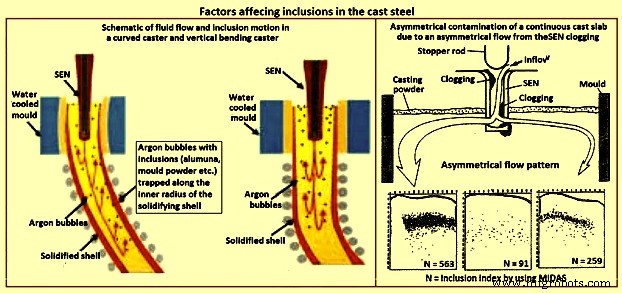
Fig 3 Factors affecting inclusions in cast steel
Casting machine curvature – Continuous casting machines with curved mould are known to entrap more particles than straight (vertical) mould casting machines (Fig 3), since the particles gradually move upwards towards the inside radius while they spiral with the liquid in the lower recirculation zone. Majority of the particles are captured 1 m to 3 m below the meniscus, independent of casting speed, which corresponds to a specific distance through the strand thickness. Frequently, inclusions concentrate at surface and one-eighth to one-fourth of the thickness from the top of the inside radius surface. The vertical bending casting machine has fewer inclusions and pinholes, which are distributed deeper, relative to the curved casting machine. Particle entrapment defects such as pencil pipe can be lessened if at least the top 2.5 m section of the casting machine is straight (vertical).
Inclusions detection methods
The quantity, size distribution, shape and composition of inclusions are required to be measured at all stages of the production of steel. Measurement techniques range from direct methods, which are accurate but costly, to indirect methods, which are fast and inexpensive, but are only reliable as relative indicators. The inclusion detection methods are sometimes divided into two categories namely (i) off-line methods, and (ii) online methods.
Direct methods
There are several direct methods to evaluate steel cleanliness. These methods are described below.
Inclusion evaluation of solid steel sections
Several traditional methods directly evaluate inclusions in a two dimensional section through solidified product samples. The last five of the methods described below add the ability to measure the composition of the inclusions.
Metallographic microscope observation (MMO) – MMO method can only reveal the two-dimensional section of an inclusion though the inclusions are three-dimensional in nature.
Image analysis (IA) – This enhancement to MMO improves on eye evaluation by using high speed computer evaluation of video-scanned microscope images to distinguish dark and light regions based on a grey scale cutoff.
Sulphur print – It is a popular and inexpensive macro-graphic method which distinguishes macro-inclusions and cracks by etching sulphur rich areas. It has the same issues as the other two-dimensional methods.
Scanning electron microscopy (SEM) – This method clearly reveals the three-dimensional morphology and the composition of each inclusion. Composition can also be measured with ‘electron probe micro analyzer’ (EPMA).However, extensive sample preparation is needed to find and expose the inclusion(s).
Optical emission spectrometry with pulse discrimination analysis (OES-PDA) – The optical emission spectrometry (OES) method analyzes elements dissolved in liquid steel. Inclusions cause high intensity spark peaks (relative to the background signal from the dissolved elements), which are counted to give the PDA (pulse discrimination analysis) index.
Laser micro-probe mass spectrometry (LAMMS) – In this method, individual particles are irradiated by a pulsed laser beam, and the lowest laser intensity above a threshold value of ionization is selected for its characteristic spectrum patterns due to their chemical states. Peaks in LAMMS spectra are associated with elements, based on comparison with reference sample results.
X-ray photoelectron spectroscopy (XPS) – This method use x-rays to map the chemical state of individual inclusions which greater than 10 micrometers in size.
Auger electron spectroscopy (AES) – This method use electron beams to map the composition of small areas near the surface of flat samples.
Cathodoluminescence microscope – Under microscope, the steel or lining sample section is stimulated by a cathode-ray (energetic electron-beam), to induce cathodoluminescence (CL). The colour of CL depends on the metal ions type, electric field, and stress, allowing inclusions to be detected.
Inclusion evaluation three-dimensional steel matrix
Several methods directly measure inclusions in the three-dimensional steel matrix. The first four of these scan through the sample with ultrasound or x-rays. The last four of these volumetric methods first separate the inclusions from the steel.
Conventional ultrasonic scanning (CUS ) – In this method, the transducer (typically a piezoelectric) emits a sound pressure wave which is transferred into the sample with the aid of a coupling gel. The sound waves propagate through the sample, reflect off at the back wall and return to the transducer. The magnitude of the initial input pulse and the reflected signals are compared on an oscilloscope to indicate the internal quality of the sample. Obstructing objects in the path of the sound scatters the wave energy. This non-destructive method detects and counts inclusions larger than 20 micrometers in the solidified steel samples.
Mannesmann inclusion detection by analysis surfboards (MIDAS) – In MIDAS method the steel samples are first rolled to remove the porosity and then ultrasonically scanned to detect both the solid inclusions and compound solid inclusions / gas pores. This method has been now renamed as the ‘liquid sampling hot processing’ (LSHP) method.
Scanning acoustic Microscope (SAM) – In this method, a cone-shaped volume of continuous cast product is scanned with a spiraling detector, such as a solid ultrasonic system, which automatically detects inclusions at every location in the area of the sample surface, including from surface to centre-line of the product.
X-ray detection – By this method, inclusions images are detected by their causing variation in the attenuation of x-rays transmitted through the solid steel. An inclusion distribution can be constructed by dividing a sample into several wafers and subjecting each to conventional x-rays to print penetrameter radiograghs for image analysis.
Chemical dissolution (CD) – In the CD method, acid is used to dissolve the steel and partially extract the inclusions. The inclusion morphology and composition can be detected by another method like SEM, or be fully extracted by dissolving the complete steel sample. The three dimensional nature of inclusions can be revealed by this method. The disadvantage is that the acid dissolves away FeO, MnO, CaO, and MgO in the inclusions. Hence, this method is good to detect only alumina and silica inclusions.
Slime (electrolysis) technique – This method is also called ‘potentiostatic dissolution technique’. A relatively large (200 grams to 2 kilograms) steel sample is dissolved by applying electric current through the steel sample immersed in a ferrous chloride or ferrous sulphate solution. This method is used to reveal the individual, intact inclusions. One disadvantage of this method is the cluster inclusions possibly break into separate particles after extraction from steel.
Electron beam (EB) melting – In this method, a sample of aluminum killed steel is melted by an electron beam under vacuum. Inclusions float to the upper surface and form a raft on top of the liquid sample. The normal EB index is the specific area of the inclusion raft. An enhanced method (EB-EV – ‘extreme value’) has been developed to estimate the inclusion size distribution.
Cold crucible (CC) melting – Inclusions are first concentrated at the surface of the melted sample as in the EB melting. After cooling, the sample surface is then dissolved, and the inclusions are filtered out of the solute. This method improves on EB melting by melting a larger sample and being able to detect silica.
Fractional thermal decomposition (FTD) – When temperature of a steel sample exceeds its melting point, inclusions can be revealed on the surface of the liquid and decomposed. Inclusions of different oxides are selectively reduced at different temperatures, such as alumina based oxides at 1,400 deg C or 1,600 deg C, or refractory inclusions at 1,900 deg C. The total oxygen content is the sum of the oxygen contents measured at each heating step.
Magnetic particle inspection (MPI) – This method also called magnetic leakage field inspection can locate inclusions larger than 30 micro-meters in steel sheet products. The test procedure consists of generating a homogeneous field within the steel sheet which is parallel to the sheet surface. If an inhomogeneity (such as an inclusion or a pore) is present, the difference in magnetic susceptibility forces the magnetic flux field to bend and extend beyond the surface of the sheet. The main disadvantage of this method is poor resolution of inclusions which are close together.
Inclusion size distribution after inclusion extraction
Several methods can find three-dimensional inclusion size distributions after the inclusions are extracted from the steel using a suitable method described earlier.
Coulter counter analysis – in this method, particles which flow into the sensor through its tiny hole are detected because they change the electric conductivity across a gap. The method measures the size distribution of inclusions extracted by slime and suspended in water.
Photo scattering method – Photo-scattering signals of inclusions (which have been extracted from a steel sample using another method such as slime, are analyzed to evaluate the size distribution.
Laser diffraction particle size analyzer (LDPSA) – This laser technique can evaluate the size distribution of inclusions which have been extracted from a steel sample using another method such as slime.
Inclusion evaluation of liquid steel
There are several approaches which can be used to detect the inclusion quantity and the size distribution in the liquid steel.
Ultrasonic techniques for liquid system – This method captures the reflections from ultrasound pulses to detect on-line inclusions in the liquid steel.
Liquid metal cleanliness analyzer (LIMCA) – This on-line sensor uses the principle of the ‘Coulter counter’ to detect inclusions directly in the liquid steel. This method is normally used for aluminum and other metals, and it is still under development for steel.
Confocal scanning laser microscope – This new in-situ method can observe the behaviour of individual inclusions moving on the surface of the liquid steel, including their nucleation, collision, agglomeration, and pushing by interfaces. The detected alumina inclusion clustering process on a liquid surface by this method is shown in Fig 4.
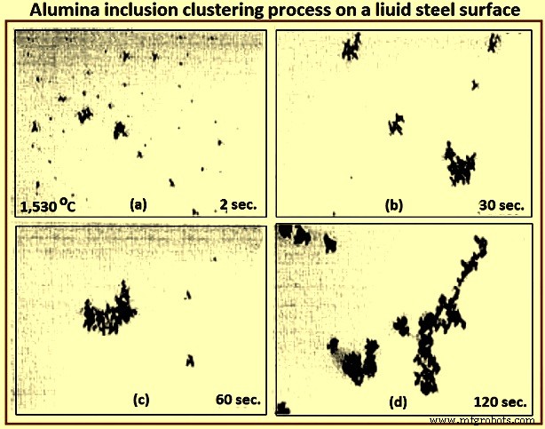
Fig 4 Alumina inclusion clustering process on a liquid steel surface
Electromagnetic visualization (EV) – This Lorentz-force-based detection system is used to accelerate inclusions to the top free surface of the sample of liquid metals and highly conductive opaque fluids. The technique has better resolution than other on-line methods.
Indirect methods
Owing to the cost, time requirements, and sampling difficulties of direct inclusion measurements, steel cleanliness is normally measured in the steel plants using total oxygen, nitrogen pickup, and other indirect methods.
Total oxygen measurement – The total oxygen in the steel is the sum of the free oxygen (dissolved oxygen) and the oxygen combined as inclusions. Free oxygen or ‘active’ oxygen can be measured relatively easily using oxygen sensors. It is controlled mainly by equilibrium thermodynamics with deoxidation elements, such as aluminum. Since the free oxygen does not vary much for example, 3 ppm to 5 ppm at 1,600 deg C for aluminum killed steel. The total oxygen is a reasonable indirect measure of the total amount of oxide inclusions in the steel since there is small population of large inclusions in the steel sample. Hence, the total oxygen content really represents the level of small oxide inclusions only. The total oxygen measured from liquid samples roughly correlates with the incidence of slivers in the product. In particular, tundish samples are normally taken to indicate cleanliness for the cast steel dispositioning.
One of the steel plants needs the total oxygen in the tundish samples less than 30 ppm to ensure shipment of cold-rolled sheet without special inspection. The general conclusions drawn from the data of the total oxygen levels in LCAK steel at each processing step at several steel plants are (i) total oxygen in LCAK steel has steadily decreased with passing years, as new technology is implemented, (ii) plants with RH (Rurhstahl Heraeus) degassing unit achieve lower total oxygen (10 ppm to 30 ppm) than plants with ladle gas stirring (35 ppm to 45 ppm), and (iii) the total oxygen normally drops after every processing step such as 40 ppm in the ladle, 25 ppm in the tundish, 20 ppm in the mould, and 15 ppm in the cast product. Fig 5 shows relationship between total oxygen in tundish and sliver defect index.
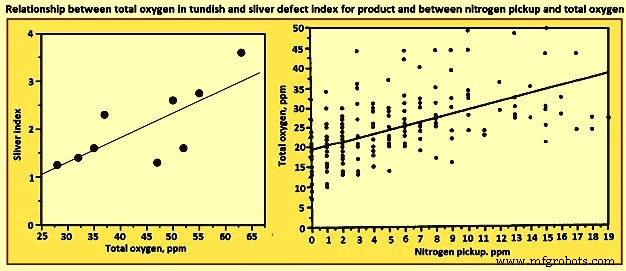
Fig 5 Relationship between total oxygen in tundish and sliver defect index for product and between nitrogen pickup and total oxygen
Nitrogen pickup – The difference in nitrogen content between steelmaking vessels is an indicator of the air entrained during transfer operations. Hence, nitrogen pickup serves as a crude indirect measure of total oxygen, steel cleanliness, and quality problems from reoxidation inclusions. For example, a steel plant restricts nitrogen pickup from ladle to tundish to less than 10 ppm for critical clean steel applications. The oxygen pickup is always many times higher than the measured nitrogen pickup, because of its faster absorption kinetics at the air steel interface. Fig 3 shows relationship between nitrogen pickup and total oxygen. In addition, nitrogen pickup is faster when the oxygen and sulphur contents are low. Hence, for the reduction of the nitrogen pickup, deoxidation is best carried out after tapping. Plant measurements confirm this, as nitrogen pickup reduced from 10 ppm to 20 ppm for deoxidation during tapping to 5 ppm after tapping.
The general conclusion drawn from the data of minimum nitrogen pickup and nitrogen contents measured in LCAK steel at every processing step (except tundish and mould) for several steel plants is that the nitrogen in LCAK steel cast products is around 30 ppm to 40 ppm at the majority of the steel plants. It is controlled mainly by the steelmaking converter or electric furnace operation, but is also affected by secondary steelmaking and shrouding operations. However, the nitrogen pickup is decreasing with passing years, because of new technologies and improved operations. Nitrogen pickup can be normally controlled at 1 ppm to 3 ppm from ladle to the mould. With optimal transfer operations to lessen air entrainment, this pickup can be lowered during steady state casting to less than 1 ppm.
Concentration measurement – For LCAK steels, the dissolved aluminum loss also indicates that reoxidation has occurred. However, this indicator is a less accurate measure than nitrogen pickup since aluminum can also be reoxidized by the slag. The silicon pickup, manganese pickup can be also used to evaluate the reoxidation process.
Lining refractory observation – Analysis of the lining refractory composition evolution before and after operations can be used to estimate inclusion absorption to the lining and the lining erosion. Also, the origin of a complex oxide inclusion can be traced to lining refractory erosion by matching the mineral and element fractions in the slag with the inclusion composition.
Slag composition measurement – Analysis of the slag composition evolution before and after operations can be interpreted to estimate inclusion absorption to the slag. Also, the origin of a complex oxide inclusion can be traced to slag entrpment by matching the mineral and element fractions in the slag with the inclusion composition. However, these methods are not easy because of the sampling difficulties and since changes in the thermodynamic equilibrium are to be taken into account.
Tracer studies for determining exogenous inclusions from slag and lining erosion – Tracer oxides can be added into slags and linings in ladle, tundish, mould, or ingot trumpet, and top compound. Typical inclusions in the steel are then analyzed by SEM and other methods. If the tracer oxides are found in these inclusions, then the source of these inclusions can be decided.
Submerged entry nozzle (SEN) clogging – Short SEN life due to clogging is sometimes an indicator of poor steel cleanliness. The composition of a typical clog during LCAK steel continuous casting consists of Al2O3- 51.7 %, Fe – 44 %, MnO – 2.3 %, SiO2 – 1.4 %, and CaO – 0.6 % , which shows that nozzle clogs are frequently caused by a simultaneous build-up of small alumina inclusions and frozen steel. Hence, SEN clogging frequency is another crude method to evaluate steel cleanliness.
Final product tests
The ultimate measure of cleanliness is to use destructive mechanical tests to measure formability, deep-drawing, and / or bending properties of the final sheet product, or fatigue life of test samples or product samples. Other steel sheet tests include the HIC test and magnetoscopy. Another example is the inclusion inspection method in ultra-sonic fatigue test. These tests are needed to reveal facts such as the potential benefit of very small inclusions (less than 1 micrometer), which are not to be counted against cleanliness.
It can be seen from the above that there is no single ideal method to evaluate steel cleanliness. Some methods are better for quality monitoring while others are better for problem investigation. Hence, it is necessary to combine several methods together to give a more accurate evaluation of steel cleanliness in a given operation.
Since exogenous inclusions can originate from a combination of several sources, methods for their prevention are not likely to be simple. It is only through the correct combination of all these sources and removal mechanisms that the incidence of large inclusions in the steels can be reduced. For the detection of the exogenous inclusions in steel, the methods which are suitable are ultrasonic scanning, microscopic observation, sulphur print, slime (electrolysis), X-ray, SEM, slag composition analysis, and refractory observation.
制造工艺