

高炉炼铁的演变
高炉炼铁的演变
第一次冶铁的起源,隐藏在人类文明史无记载的历史中。古代使用铁器的第一个证据实际上来自埃及,在金字塔的两块石头之间的接合处发现了一种铁器。许多史前铁器的起源可能是陨铁。流星铁含有 5% 到 26% 的镍(Ni),而熔炼的铁只含有微量的镍,因此由流星制成的铁制品可以与熔炼铁的物体区分开来。
4000多年前,人们发现了陨铁。但又过了 2000 年,才开始从开采的铁矿石中生产铁。印度最早发现的冶炼铁可以追溯到公元前 1800 年(普通时代之前)。据说大约在公元前 1500 年,赫梯帝国的臣民亚美尼亚的卡吕布人开始炼铁。当他们的帝国在公元前 1200 年左右崩溃时,各个部落将炼铁知识带到了欧洲和亚洲。整个欧洲和西亚的铁加工知识最终都可以追溯到这个来源。铁器时代始于发现铁的冶炼。
炼铁开始
与硫化铜矿石的还原一样,氧化铁的第一次还原可能是偶然的。正是这种观察力使这些古代冶金学家(他们那个时代的矿工、化学家和技术专家)意识到可以通过氧化矿石的直接碳 (C) 还原在简单的熔炉中生产铁。在公元前 1500 年左右的埃及坟墓的墙上发现了第一个关于冶炼过程的记录描述。 (图 1)这个过程是一个简单的矿坑,里面有矿石和未知燃料,通过使用脚踏波纹管使火势加剧。在接下来的 3000 年里,铁的生产技术并没有发生重大变化,而是由氧化物碳还原生产的海绵铁和捣碎海绵制成的铁制品。
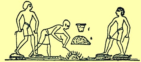
图1埃及古墓中描绘的炼铁过程
地球上的许多地区都存在氧化铁矿石。因此,大致在埃及进行铁矿石还原的同时,其他地区也正在这样做。印度、中国、非洲和马来亚是最初发展炼铁实践的地点。这些国家开发的熔炉都非常相似,这可能很重要。形状和大小有所不同,但功能相同. 化学还原成铁而不熔化,得到的金属比较纯净和柔软,被称为熟铁。它可以锤打成有用的形状。长矛、箭尖、匕首和其他工具和武器都可以用它来制造熟铁。
大约 2000 年,直到大约公元第一个千年(共同时代)结束,铁是通过“开花”工艺在当地的小型炉膛中生产的。这些结构的尺寸在考古调查中是不可用的,但现代重建的布卢姆里炉的内部尺寸为 300 毫米直径。 x 1000 毫米高。在Bloomery过程中,建造了一个炉膛,并在其中放置了多层木炭和铁矿石,直到产生一个土堆。在这个土丘周围建造了一个粘土和砖块外壳,在顶部留有一个洞用于排放废气,在底部留一个洞用于通过操作波纹管产生的空气冲击。然后点燃木炭,风箱工作,直到木炭耗尽。然后外壳被打开,如果这个过程进行得很好,那么就会有一堆海绵状的铁和一滩矿渣。用锤子敲打热的海绵铁以生产铁坯或铁制品。此处描述了在大灯冶炼过程中发生的反应。炭火产生一氧化碳 (CO),热量驱走沼泽矿石中的水分,产生赤铁矿。一氧化碳将赤铁矿还原为氧化亚铁、方铁矿。然后 CO 将方晶石还原为元素铁。反应并没有一直持续下去。它进入平衡位置,因此产生的气体是一氧化碳和二氧化碳(CO2)的混合物。然而,wüstite 也可以与任何沙子反应生成铁橄榄石(铁橄榄石),这是产生的炉渣的主要成分。就冶炼过程而言,这种铁橄榄石是一条死胡同,因为它在熔炉条件下无法还原为元素铁。生产的铁的熔点约为。 1,540 摄氏度,而炉渣熔点约为 1,100 摄氏度。达到的温度足以熔化炉渣,但不足以熔化铁。该过程运行良好,尽管剩余的炉渣仍然含有大量的铁,通常高达或超过 60% 的 FeO(氧化亚铁)。矿渣有两种,一部分是沼泽矿渣的开孔性质,一部分是从红色铁矿石中获得的致密、坚硬且非常难熔的。
炼铁工艺的发展
第一个炼铁工艺的改进是在冶炼孔内衬上石头和泥土,并使用木头和皮革制成的波纹管(图 2)。在中国,铁的使用出现在公元前 600 年左右,在公元前 403 年至公元前 222 年期间广泛传播。中国人开发了优越的炼铁技术,早在公元前200年,基于铸铁器皿的发现就生产了液态铁。中国和印度的古籍都提到炼铁。其他文物包括剑、斧头、镰刀和锄头。到公元 310 年,可以生产出足够数量的铁来竖立印度德里和达尔著名的铁柱。德里的锻铁柱高 18 m,直径 410 mm,重 17 吨。在日本,被称为“Tatara”的传统钢铁制造工艺直到公元 17 世纪才得到充分发展。在北美、南美和澳大利亚,古代居民并不知道炼铁。炼铁技术是欧洲人带到这些国家的。
围绕地中海发展起来的炼铁工艺已经向北传播到整个欧洲。腓尼基人、凯尔特人和罗马人帮助传播了炼铁技术。罗马人向北传播到英国的炼铁技术之一是早期的碗或竖炉。该炉由一个碗形容器或一个 2 m 高的圆柱形竖井组成,该竖井建在山的一侧。用来扇动炉内火的空气是由靠近盛行风的碗底部建造的开口提供的。炉子通过顶部开口装满木炭和铁矿石层,通过下部开口点燃。
关于炼铁是如何被驱动的,有两种理论,一种是风从底部开口吹进来,提供加热过程的空气,另一种是风吹过开口顶部,沿着内侧前壁形成低压区域它通过下部开口吸入空气(图 2)。在这两种情况下,该过程都依赖于风,并且全年都不可靠。产品又是一团海绵铁,通过下部开口取出,然后锤打成最终形状。
另一种早期的炼铁厂是蜂巢炉(图 2)。这个炉子是在平坦的地面上通过交替堆放木炭和铁矿石而建造的。土丘上覆盖着一层厚厚的粘土,连接到波纹管的吹管穿过下部侧壁。底层木炭被点燃并由波纹管提供加压空气。在这批式熔炼结束时,粘土穹顶坍塌。生产的海绵铁从拆除的蜂箱炉中挖出进行锤击。这些熔炉生产的是小块铁,每次生产后都必须拆除和重建冶炼炉。
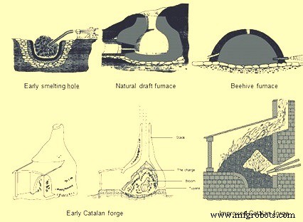
图2早期炼铁过程
这些类型的炼铁工艺在现代使用了数百年,没有太大的改进。然后大约在 8 世纪期间,在西班牙东北部的加泰罗尼亚山区运营的一家小型锻造厂代表了炼铁领域早期的重大冶金进步之一。早期的加泰罗尼亚锻造(图 2)有一个称为炉膛的石制杯子,高约 910 毫米,直径约 760 毫米。底座前部上方一小段距离是一个小开口,可以安装一个称为风口的喷嘴。风口喷嘴连接到波纹管以供空气。炉膛里装满了木炭块,直到风口处。然后将铁矿石放在风口上方,并在矿石上铺上更多的木炭。木炭被点燃,来自风箱的空气将热二氧化碳压在矿石上,从而将铁矿石还原成炽热的块状铁块。被称为大华的铁块重达 160 公斤,可以用钳子从锻炉的炉膛中取出,而不会破坏石头结构。这个数量的铁可以在 5 小时内产生,而以前的技术只能在 5 小时内产生约 23 公斤。在接下来的 200 年里,加泰罗尼亚锻造厂的规模不断扩大,其使用范围扩大到法国、比利时、英国和德国。炉膛的大小增加到 1 平方米,由矩形石块建造。通过使用称为“trompe”的空气吸气器,也增加了通过风口输送的空气量。当水通过错视柱落下时,空气被吸入管中,然后从盒子底部排出。当这个装置被集成到 Catalan Forge 中时,通过风口的爆炸压力为 0.10 到 0.14 kg/sq cm,这远远超过手或脚风箱所能产生的压力。这种额外的鼓风压力加速了冶炼过程并提高了产量。
从 10 世纪到 14 世纪,加泰罗尼亚的熔炉经历了进一步的演变。手或脚操作的波纹管被水车操作的波纹管取代,这增加了空气喷射的体积和压力。接下来,尝试通过增加堆栈的高度并从堆栈顶部装入铁矿石和木炭来捕获来自锻造堆栈的废热,以便可以预热矿石。这些熔炉有一个由 1.8 m 到 4.8 m 高的石砌体制成的烟囱。烟囱高度以及原材料装料的高度可能会增加,这是因为更高的爆炸压力可能会从水车操作的波纹管中迫使这些烟囱向上。
最高的 Stuckofen 熔炉(图 3)不仅有 4.8 m 高的烟囱,而且烟囱的几何形状也发生了变化。炉子的形状是两个截锥体,以最宽的直径连接起来。两个风口成为标准,因为水车驱动两个风箱,其中一个不断被压缩以提供爆炸。熔炉底部有一个开口可以排出炉渣,但必须拆除石料才能提取最终产品,最终产品仍然是重约 318 公斤的铁块。 Stuckofen 熔炉一年可生产 100 至 150 吨,超过了加泰罗尼亚锻造厂的生产能力。这种熔炉的一种副产品是液态铁。由于铁矿石在熔炉中的停留时间较长,以进行化学反应并暴露在较高的温度下,因此铁可以吸收更多的 C,从而降低了熔点。当钢坯从炉中取出时,这种液态铁也被取出。起初它被认为是有害的,因为它太脆而不能用锤子加工。在某些情况下,它被重新装入熔炉,甚至作为废物丢弃。 Stuckofen 高炉被认为是现代高炉 (BF) 的先驱。它被进一步修改为“Blauofen”(吹炉),能够根据铁制造商的判断生产液态铁或锻造级海绵铁。所需产品的这种变化是通过将装料量改变 10% 至 15% 并将风口的位置降低 500 毫米并将它们推入炉内更深来实现的。在 16 世纪,这些熔炉高 6.7 m,每天可生产约 1.8 吨铁,每生产 100 公斤铁可生产约 250 公斤木炭。这些熔炉的预期寿命约为 45 天。
一直以来生产液态铁的熔炉设计的下一步是“Flussofen”(流动炉)。 Flussofen 或第一个 BF 的开发是在 14 世纪在莱茵河谷和法国、比利时和德国的邻近地区。然而,随着战争和炼铁技术的变化,用铁水铸造大炮成为主导产业,而不是用海绵铁锻造剑。早在公元 1300 年,钢铁制造商就积极寻求生产液态铁来铸造枪支。已知 BF 的第一个可靠文件是在公元 1340 年,当时比利时的 Marche Les Dames 的熔炉建成。 Flussofen 或 BF 的传播相对缓慢。欧洲大陆国家有资格从加泰罗尼亚熔炉中生产铁坯的原始方法充分发展出高炉。现代高炉是由Stuckofen和Flussofen逐渐演变而来的竖炉。
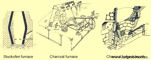
图 3 Stuckofen 炉和木炭炉
木炭高炉的演变
在欧洲大陆开发的木炭高炉(图 3)很快传播到英国,在那里发生了炼铁技术的下一次发展。公元 1565 年在英格兰蒙茅斯郡建造的高炉是在迪恩森林中建造的第一座熔炉,后来成为主要的炼铁中心。该高炉高 4.6 m,炉腹处 1.8 m,这是炉内两个截锥相交的最宽点。到公元 1615 年,有 300 个高炉,平均每个熔炉每天大约 2 吨。增长速度如此之快,以至于导致木炭生产的土地被完全砍伐。在 1600 年代,为了保护剩余的森林,实施了法定限制,许多高炉被关闭。
北美第一座高炉于 1622 年在弗吉尼亚州的 Falling Creek 建造。由于所有工厂工人被杀,铁厂被美洲原住民摧毁,该熔炉从未投入使用。北美第一个成功的木炭高炉始于 1645 年,位于马萨诸塞州的索格斯。这个高炉有一个 6.4 m 高的烟囱,外壁在上升时向内倾斜,底部为 7.9 m 方形。炉子是用花岗岩和其他当地的石头用粘土砂浆粘合而成的。它停在平坦的地面上,地下排水系统被切开以防止潮湿,驱动它的大风箱轮的水使它特别容易受到潮湿的影响。 BF 有一个内部大致呈蛋形的烟囱,最大直径为 1.8 m,称为炉膛顶部。向下倾斜的波什支撑着矿石、熔剂和木炭的装料。一个称为炉膛的方形坩埚位于炉腹底部,并衬有砂岩(图 3)。在内衬和外砌体之间有一个带有沙子、粘土和碎石的内墙,在加热和冷却循环期间充当膨胀和收缩的缓冲垫。两道外墙有大而深的拱门。通过较小的拱门,通过两个 5.5 m 波纹管的前端和两个风口,将爆炸送入高炉。在较大的拱门下是炉膛和铸造地板的工作区。坩埚或炉床充当液态铁的储存器。炉床底部为 460 mm 正方形,但在达到 1.1 m 的全高时扩大到 530 mm。其下部的突出部分,称为前炉,由两堵墙和一个森林或水坝组成。上面,在大坝后面是一堵石头幕墙,叫做“鼓室”,它的底部边缘低于大坝的顶部。通过鼓膜和水坝之间的开口,操作员用勺子舀出用于模具铸造的铁,并用一根称为振铃器的铁棒撬开粘在墙上或积聚在风口鼻子周围的炉渣。为了防止此类操作的磨损,鼓室和大坝都用铁板包裹着。通过在称为煤渣槽口的位置将液体材料耙过坝石来完成除渣。然而,要出铁,需要在一个前炉侧壁和大坝一端之间的一个狭窄空间(称为出铁孔)中打开一个粘土塞。
除了这项复杂的砌体工作外,BF 的安装还涉及木材和皮革工作。在高炉顶部和相邻的断崖之间有一座重型木结构,称为充电桥。原材料是用独轮车从悬崖上的库存中取出的,穿过充电桥到达高炉的顶部。高炉顶部的三个侧面是木制的挡风玻璃,为操作人员将原材料投入到冒烟、火花和偶尔火焰的装料孔中提供了一些安全的庇护所。位于地面的高炉烟囱的两侧被称为铸造房的木制倾斜结构包裹。这种结构为沟槽和模具铸造区域以及波纹管提供了覆盖。两个波纹管由连接到超调水车的凸轮轴以往复方式驱动。波纹管由主轴上的凸轮放气,并由由装满石头的木箱组成的配重充气,并安装在移动横梁上,这些横梁通过切割成容纳它们的孔延伸到铸造房屋顶之外。高炉每生产一吨铁消耗铁矿石 3 吨、熔剂石 2 吨和木炭 2.6 吨。出铁口每天打开两次,每次浇铸时都会排出大约 450 公斤的液态铁。将铁水拉入单沟或舀入砂模,生产锅、锅、炉盘等国产产品。
在接下来的 100 年到 1700 年代,上述炭铁制造仅略有变化。 BF 烟囱的尺寸增加了,吹塑设备也得到了改进。 1700 年代的典型木炭高炉尺寸增加了 9.1 m 高度和 2.4 m 的炉腹直径。只有通过改进导致更高爆炸压力的风力输送设备才能增加高炉尺寸。爆破系统的第一个改进是发明了木制吹风桶,它可以是方形的,也可以是圆形的,类似于用外部钢箍固定在一起的木桶。水车上的偏心曲柄在每一侧都有一个往复式活塞杆和吹气桶。浴缸内的活塞装有皮革以形成密封。当一个活塞上升以压缩一个桶中的空气时,另一个活塞在另一个桶中下降。每个浴缸的顶部都有一个出口管,连接到一个始终处于压力下的公共混合箱。混合箱将压缩空气输送到通向炉风口的空气管道或鼓风总管。一个典型的吹风桶直径为 1.8 m,高 1.8 m,产生 0.14 kg/sq cm 的爆炸压力。 1760 年,英国的约翰·斯米顿(John Smeaton)将木制吹制桶的概念更进一步。他将木桶改造成铸铁桶,首先由水车驱动,然后在 1769 年由蒸汽机驱动。 1769 年,苏格兰建造了第一台使用蒸汽驱动吹制发动机的高炉。蒸汽驱动吹制发动机的发明导致更高的爆破压力,从而允许进一步使用矿物燃料(焦炭和煤)。 1700 年代的这些改进导致高炉产量从 1600 年代高炉的 1 吨/天增加到 1700 年代后期的 3 至 5 吨/天。这与矿物燃料的使用一起导致欧洲的木炭炉数量迅速下降,尽管随着人口向西部迁移,那里有大量木材可供使用,北美的木炭铁产能有所增加。
在 1800 年代,炭铁产量达到顶峰,然后下降。 1800 年代中期,在拥有茂密原始森林的宾夕法尼亚州和密歇根州上半岛发现了优质铁矿石。该地区建造的木炭高炉规模最大,装备最好。这些高炉的堆垛高度为 13.7 m,炉腹直径为 2.9 m。风口的数量从两个增加到三个,炉膛的三个侧面各一个,出铁口在第四个侧面。吹瓶设备通常是水平吹瓶,典型直径可达 1270 毫米,冲程为 1.5 米。电梯式平台升降机取代了装料桥,所有铁矿石和焊剂都被称重,作为标准装料的一部分。木炭仍然被一辆大手推车的体积充电。铁壳板慢慢取代了砌筑石堆,天然石衬里升级为氧化铝砖。
安装在这些木炭炉上的主要技术改进之一是装料设备。最初,原材料通过隧道头倾倒到开口的堆垛中。 BF 操作员意识到开顶熔炉有两个缺点,首先,离开烟囱的可燃气体无法被捕获用于燃烧锅炉,其次,原材料的分配导致熔炉运行效率低下。 1832 年,德国首次尝试捕获气体,结果是在装料孔上安装了一个铰链盖,只有当原材料从独轮车倾倒时才打开(图 4)。一个开口也被放置在位于上烟囱的炉子的一侧。这个开口装有一个称为下降管的管道,将高炉气体输送到地面,在辅助设备中燃烧。
由于原料装料导致高炉效率低下的问题需要一个更复杂的解决方案,该解决方案通过几个步骤进行演变。这种效率低下的原因(用高燃料率描述)是因为细料通过高炉中心的装料孔倾倒在堆的中心,而粗颗粒滚落到炉壁。这导致高炉外围的渗透率更高,因此大部分气体和热量向上移动。这对 BF 操作是有害的,因为 BF 中心的材料在没有准备好熔化的情况下到达了炉腹区域,同时在壁上过多的气流加剧了衬里磨损。解决这一负载分配问题的第一个尝试是引入充电设备“杯锥”(图 4)。它由一个倒置的锥形铸铁漏斗组成,该漏斗固定在炉子的顶部,向装料孔进料。这个锥体大约是喉部直径的 50%。锥体内有一个铸铁杯,它悬挂在一个支点梁上,对着一个配重。使用连接到配重的绞盘手动提升杯子。该设备成功地捕获了气体,但仍有大量粗材料滚到墙上。对杯锥设备的下一个修改是在炉内悬挂一个铸铁截锥(图 4)。这导致原材料的峰值移动到更靠近炉壁的位置,因此粗颗粒现在也可以滚动到炉子的中心,从而产生更好的中心渗透性和气流。
完全消除杯子和锥体的下一个进料步骤是悬挂一个向下开口的倒锥体(图 4)。这是第一个钟形 BF 顶部。该钟成功地推动了壁峰,从而减少了外围的气流并增加了中心的气流,但是随着钟的每次降低,高炉气体从烟囱中逸出。对此的解决方案是为充电孔安装一个铃铛和一个盖子。当材料从独轮车中倾倒出来时,盖子已打开,但钟罩已关闭,气体仍留在 BF 中。然后盖上盖子,倾倒钟,这也将气体保留在高炉中,同时产生适当的负荷分布。这些改进的结果是提高了高炉内的物理和化学反应效率,从而减少了燃料需求,提高了生产率并减少了耐火衬里的磨损。
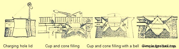
图4 BF顶级设备的演变
由于许多设计改进导致高炉产量增加,液体产品(铁和炉渣)的去除成为一个问题。木炭高炉的产量在此期间从每天 1 吨增加到 25 吨。每天通过出铁口前的一条沟进行两次铸件无法处理如此高的吨位。铸造房屋建筑的尺寸增加到大约 12 m 宽和 21 m 长。铸造车间包含用于铸铁和除渣的单独区域。用于除铁的一侧由一个称为槽的大沟槽组成,该槽从熔炉前部向下倾斜到充满沙子的铸造车间地板。然后它溢出到两个流道系统中。每个系统上的主流道与铸造车间的长度平行。当这个跑步者下坡时,会定期建造一系列水坝。在每个大坝前的一个直角处,沙子中形成了一个称为“母猪”的较小的跑步者。然后从这头母猪身上长出许多称为“猪”的蛀牙。之所以应用这些名称,是因为该系统看起来像一排正在哺乳母亲的小猪(图 5)。有几排平行的母猪和猪是通过在铸造房地板上的潮湿沙子中推动 D 形木板产生的。在浇注过程中,由于每头母猪和猪都充满了液态铁,主浇道上的沙坝被一根棒子撞倒,熔融金属从山坡下流到下一个母猪和猪床。有两个完整的系统允许更频繁地铸造 BF。由于一侧装满了铁水,另一侧的猪被移走,床被重新改造。
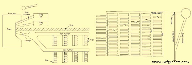
图 5 铸造车间的猪床
铸造房的另一侧用于除渣。矿渣不断地从大坝前部顺着矿渣流道跑到矿渣坑中。高炉前部的渣坝被分成两半,每半喂一个单独的渣流道和渣坑。渣坑是沙中的一个大凹陷,底部有山脊。当需要清除凝固的炉渣时,这些脊充当了断裂点。在一些铸造厂,使用悬臂式木制起重机吊起大块炉渣。如果铸造厂操作员发现渣层太厚,他们通常会在液态渣的中心放置一根钢筋。然后当炉渣在钢筋周围冷却时,可以用绳索或链条缠绕它,然后用起重机吊起大块的炉渣。除渣方面,还有两套完整的渣系统,一个在使用的同时,另一个可以清洗和准备。
据了解,“铸造”一词的起源来自对液态铁从熔炉中“浇铸”出来的看法。铸造操作由两部分组成。在第一部分,当高炉中形成液态炉渣时,它会漂浮在液态铁的顶部,直到它达到足够高的水平,以便在鼓室和大坝之间流入渣流道和矿坑。铸造的第二部分是从炉膛中取出液态铁。首先是关闭爆破,然后用大锤将尖头棒打入出铁口。液态铁顺着槽流进每头连续的母猪和它的猪身上。当铁水停止流动时,人工用沙子和耐火粘土或沙子和煤的潮湿混合物堵塞出铁口。然后将鼓风送回熔炉。
浇铸完成后,铸造厂的操作员从猪床中取出凝固的铁。当猪凉到可以处理的时候,它们就被送出去了。这个循环每天重复六次,每次铸件生产 4-6 吨。生产的生铁分为不同的等级。木炭铁的硫含量低,因此产生了一种坚韧的灰口铸铁,用于生产轨道和轨道车车轮,以支持 1800 年代不断扩大的铁路。
木炭高炉在 1800 年代后期停产,因为它们的生产成本不再能够满足来自矿物制铁实践的竞争。
基于矿物燃料的炼铁
由于维持木炭炼铁所需的原始森林枯竭,因此有必要寻找替代燃料来源。这种替代燃料以烟煤、无烟煤、焦炭甚至泥炭的形式出现。在 1700 年代和 1800 年代,焦炭和无烟煤炼铁的发展相互平行,并与木炭生产并存。烟煤和泥炭的使用受到限制,从未成为主要的炼铁燃料。使用矿物燃料炼铁始于英国,因为木炭生产造成的森林砍伐首先发生在英国。
1708 年,亚伯拉罕·达比在什罗普郡租用了一个小型木炭高炉,到 1709 年他开始生产焦炭。从 1709 年到 1718 年,焦炭与木炭的混合比例越来越高,1718 年高炉使用 100% 的焦炭。直到 1750 年,三个定期使用可乐的 BF 都属于达比家族。焦炭的使用在 1750 年至 1771 年期间传播开来,共有 27 个高炉使用焦炭生产铁。焦炭的使用增加了铁的产量,因为它比木炭强。它可以支撑更多原材料的重量,因此可以增加BF的尺寸。 Coke also improved permeability in the BF, allowing a larger volume of wind to pass through the furnace. This larger volume of compressed air was provided by the steam engine and blowing cylinders.
The use of coke in continental Europe spread slowly. Coke was used in Le Creussot, France in 1785, Gewitz, Silesia in 1796, Seraing, Belgium in 1826, Mulheim, Germany in 1849, Donete, Russia in 1871 and Bilbao, Spain in 1880. In North America, the first use of 100 % coke as the fuel was in 1835 at Huntington, Pennsylvania. However, since 1797, coke was mixed with other fuels in BFs of US.
The efficient use of coke and anthracite in producing iron was accelerated not only by the use of steam-driven blowing equipment but also by the invention of preheating of the air being blown in the BF. In the beginning of the 19th century, it was believed that use of cold blast improved both the quantity and quality of pig iron since it was observed that the production of the BFs was more in winter months and it was erroneously concluded that the lower blast temperature was the reason. But the BF performance improved during the winter months due to the fact that the air was having lower humidity so that more combustion of fuel was supported by a given volume of air blown into the furnace.
In 1828, James Neilson patented his invention of supplying preheated air blast to the tuyeres. The heating equipment was a simple wrought iron box having dimensions 1.2 m x 0.9 m x 0.6 m. This wrought iron box was externally heated. The maximum blast temperature which could be attained with this box was 93 deg C and one box was needed for each tuyere. In 1832, Neilson improved his invention by constructing a larger oven by joined flanges, formed a continuous length of 30 m and provided a heating surface of 22.3 sq m. This oven, which was fired with solid fuel, produced a hot blast temperature of 140 deg C. Since this invention, continuous modification and improvement in the hot blast ovens were made and by 1831, Dixon developed a taller oven with U-shaped pipes that supplied hot blast at 315 deg C. By 1840, about 55 % of pig iron at Great Britain was produced with hot blast.
With the increase in the hot blast temperature, there was decrease in the quantity of fuel needed and increase in the BF production. However the hot blast equipment needed a lot of maintenance. The cast iron pipes supported within a brick oven had different expansion characteristics, which resulted in several cracked pipes. Another issue was that the delivery equipment used for the cold blast, which consisted of solid tuyeres and flexible leather joints between pipes, could not withstand the high temperatures. Another issue with the original hot blast systems was the increased cost of solid fuel to heat the ovens. These issues helped further improvements in hot blast equipment. First, solid fuel used for heating was replaced with BF gas. Initially primitive heat exchanger type hot blast equipment was built on top of the BF and simply used the waste heat to preheat the cold blast running through the cast iron pipes. Then the BF gas from the furnace top was conveyed to the hot blast oven where it was burned to generate heat. This type of hot blast oven became quite complex with numerous rows of vertical pipes. The issue of cracking of the cast iron pipes was tackled by eliminating the pipes and using refractory. For using this method, 2 to 4 stoves were installed for each BF. As one stove was being heated by the burning the BF gas, another was being drained of its heat by heating of the cold blast. In 1854, the Cambria Iron Works was the first plant in the US to use regenerative stoves. The stoves were constructed of iron shells, internally lined with refractory and containing refractories with multiple passages for the blast. A typical stove of this design had 186 to 232 sq m of heating surface. These stoves were representative of those produced by Cowper and Whitwell in 1857. The Whitwell stoves erected in 1875 were 6.7 m in diameter, 9.1 m high and had a total heat surface of 8546 sq m. These were the first stoves to use hexagonal refractory checkers, cast iron checker supports, and a semi elliptical combustion chamber to improve distribution of gas through the checkers. These stoves could supply hot blast to the BF with temperatures of 454 deg C to 566 deg C. This stove design has remained basically the same till date with minor modifications in refractory type, checker shape and stove size.
The other improvement in equipment required by the use of hot blast was the design of the tuyeres and the tuyere stock. The solid cast iron or cast copper tuyeres used on cold blast furnaces were replaced by water cooled tuyeres which were hollow, conical shaped castings which had water circulating through their interior. The pipes from the blowing engines to the tuyeres, which were jointed with leather on cold blast furnaces, were redesigned with metal-to-metal seats. As hot blast temperatures increased the inside of these blast mains and tuyere stocks were lined with refractory, which required an overall increase in size.
The use of hot blast was applied to both coke and anthracite furnaces. As blast pressure increased with new blowing engines, it was found that anthracite could be charged with charcoal to improve the BF productivity. During 1986 the first attempt was made to use anthracite in a cold blast furnace in eastern France. This attempt failed since the ignited anthracite broke up into small pieces and blocked the blast from entering the BF. The evolution of coke iron making and anthracite iron making paralleled each other in the US during the 1800s. In 1826, a small BF was erected in Pennsylvania to operate exclusively on anthracite coal. This practice was unsuccessful both there as well as at other places in the US. During 1833, Dr. Frederick Geissenhainer successfully used hot blast in experiments to smelt iron with anthracite coal. In 1836 the Valley furnace in Pennsylvania used 100 % anthracite and in 1837, George Crane produced 36 tons of anthracite iron per week from one of his BFs at South Wales. David Thomas was the most successful iron maker in using the anthracite in the BF. In 1838 he came to the US and built the Catasauqua BF in 1840 (Fig 6). The furnace was 10.7 m square at the base with 3.6 m bosh and a height of 13.7 m. The hot blast stoves, fired with coal, were capable of heating the blast to 315 deg C. Since this BF successfully produced 50 tons of good foundry iron per week, the furnace was used as a model for the construction of blast furnaces built for using anthracite as a fuel. By 1856 there were 121 anthracite furnaces in operation in the US.
Other fuels were also tried for iron making in the BF. These were peat and bituminous coal. Peat BFs were similar to charcoal furnaces and typically were no higher than 6.7 m. Because the peat was physically weak, the use of these furnaces was located near to the peat deposits and they never played a major role in iron making evolution. Bituminous coal had been used to supplement charcoal prior to the introduction of hot blast. In the 1830s, splint coal was used in Scottish hot blast furnaces. In 1856, there were 6 BFs in Pennsylvania and 13 BFs in Ohio using bituminous coal. The bituminous coal era of iron making was essentially finished by 1895. This method of iron making never became a major force since the coal broke up into small pieces as the BFs were made larger and used higher blast pressure. With coke being the strongest and most available fuel, the evolution of 100 % coke furnaces continued. However there were initial setbacks probably due to low strength coke. By the 1840s coke quality had improved through the use of beehive ovens. In 1867, the ‘Monster’ blast furnace was built at Norton, England. This coke furnace was 25.9 m high, 7.6 m across the bosh and had a working volume of 735 cum. An example of a large coke furnace in the US in 1884 was the Etna furnace located near Pittsburgh. This furnace was 21.3 m high, 6.1 m in diameter at the bosh, 3.4 m in diameter at the hearth and had seven 7 inch (178 mm) tuyeres, three Whitwell stoves and three blowing cylinders that were 2.1 m in diameter. This BF produced 115 tons/day in 1881, 161 tons/day in 1882 and 182 tons/day in 1883. The coke furnace design at this time was very similar to the anthracite furnaces of the same era (Fig 6).
Further evolution of coke blast furnace
The evolution of BFs using 100 % coke continued with major improvements being made between 1872 and 1913. Several technological improvements were made which were centered on the hard-driving BF practice of using more powerful blowing engines, higher blast temperatures, bigger furnaces, better charging equipment, improved raw material preparation and production of clean BF gas.
Blowing equipment design and capacity was a major step to higher production in the hard-driving BFs. Blowing cylinders were replaced with large steam reciprocating blowing engines capable of providing a greater volume of blast air at a significantly higher blast pressure. These blowing engines were of the walking beam, steam condensing type. The steam cylinder’s piston rod was connected to a gallows beam and then by a crank to a heavy, large diameter flywheel. The blowing cylinder’s piston rod was connected to the other end of the gallows beam and each stroke of the steam cylinder provided a corresponding stroke of the blowing cylinder. Cold blast pipes were fitted to each end of the vertically positioned blowing cylinder so that air was compressed on both directions of the stroke. The flywheel provided momentum for the return stroke of the steam cylinder. The air that was compressed in this manner left the cold blast pipes and entered the cold blast main which connected to the hot blast stoves. Prior to this type of blowing engine the normal blast volume was 210 cum/min at a blast pressure of 0.28 kg/sq cm. This blowing engine could produce 456 cum/min at a blast pressure of 0.64 kg/sq cm. Then in 1910, the final major step in blowing engine improvement was implemented in the form of a turbo-blower. The first turbo-blower was installed for the BF of the Empire Steel Co. in New Jersey and was capable of delivering 636 cum/min of air blast. This turbo- blower was the direct ancestor of the modern turbo-blower which can deliver up to 7500 cum/min of blast volume at 4.00 kg/sq cm of blast pressure.
Another major improvement in high productivity BFs was to increase the charging capacity. In the 1870s the BFs were equipped with water driven elevators. In 1883, the first skip hoists were installed. Skips have become larger and faster into the 20th century and existed as both buckets and cars mounted on wheels. In the early 1960s some skip charging systems were replaced with large conveyor belts.
The improvements in furnace charging capacity also included automatic coke charging systems, scale cars in the stock house, two bell tops and the rotating distributor (Fig 6). Automatic stock line measurement was invented in 1901 by David Baker. In 1903, JE Johnson also began to measure top gas temperature and its analysis.
By 1850 as the furnace size increased, the furnace top could be closed. A single bell and hopper arrangement could be used for charging the furnace that kept the top of the furnace closed and sealed. The single bell and hopper system permitted large quantity of gas to escape every time the bell was opened. Soon a second bell and hopper was added above the first so that a gas tight space could be provided between the two bells to prevent the blast furnace gas escaping when the small bell was opened. The upper bell and hopper did not have to be as large as the lower one because several charges could be deposited through it on the lower bell and the upper bell could be closed before the lower bell was opened for dumping the charges in the furnace
Attempts to improve burden distribution occurred in the early 1990s with the McKee rotating top. After each skip of material was charged onto the small bell, the small bell hopper was rotated 60 deg, 180 deg, 240 deg, 300 deg, or 0 deg. This prevented a peak of raw material directly below the skip bridge which had resulted in uneven gas distribution and uneven lining wear. The next attempt to improve burden distribution was done in Germany in the late 1960s. This was accomplished by installing movable panels at the throat of the BF that could be set at different angles for ore or coke. This movable armour has been installed on large numbers of BFs.
The two bell system continued to be the only charging system for the blast furnaces around the world till S.A. Paul Wurth in Luxembourg, developed bell less top (BLT) charging system and the first successful industrial application of BLT charging system was in 1972. This equipment used air tight material hoppers that fed a rotating raw material delivery chute which could be set at numerous angles during the hopper discharge into the furnace. The result was the almost unlimited placement of each material anywhere on the burden surface which allowed the operator to achieve maximum fuel efficiency.
The BLT charging system took over from two bell charging system since it provided a number of advantages to BF operators. During 2003, Siemens VAI introduced Gimbal concept of charging.
Another attempt in the direction of the continuous improvement of the BFs for increasing the production was towards improvements in the cleaning of BF gas. As blast volume and pressure increased at the tuyeres, the velocity and volume of gas leaving the BF top also increased. More flue dust was then carried by this waste gas and if it was not removed, it began to plug up stove checkers which subsequently restricted blast volumes to the furnace. The first step in gas cleaning was the introduction of the dust catcher in the 1880s. With the introduction of the soft iron ores in 1892, the dry-type dust catcher was not sufficient. In 1909, Ambrose N. Diehl introduced a wet gas cleaning system. It consisted of a series of nine high-pressure spray towers and a set of four rotary washers. From 1914 to 1924, several types of tower washers equipped with multiple banks of sprays and baffles were tried at various furnaces. Gas disintegrators which contained high speed rotary drums were also tested in 1907. In 1929 electrostatic precipitators were used successfully at South Works of U.S. Steel. Today, combinations of tower-type gas washers, Venturi scrubbers and mist eliminators are the most common types of gas cleaning equipment.
The newest wet gas cleaning equipment is an annular gap scrubber which cleans the gas as well as controls top pressure. The final result of all these gas cleaning improvements was a decrease in stove checker brick hole diameter with an increase in stove size because plugging with dirt had been virtually eliminated. The resulting increase in stove heating surfaces has ultimately allowed modern stoves to deliver up to 1270 deg C hot blast temperature. The associated top pressure control allowed by modern gas cleaning equipment has resulted in furnace top pressures up to 2.3 kg/sq cm. This higher top pressure in turn increases the density of gases, decreases gas velocity and increases gas retention time in the furnace, yielding better gas-solid reactions, improved reducing gas utilization and lower fuel rates.
Recently, on the newly built and reconstructed BFs, particularly in China, dry cleaning of BF gas by bag filters has found the wide application. Dry cleaning of gas has several advantages over wet gas cleaning using scrubbers and Venturi tubes.
The quest for higher production rates in the late 1870s and onwards forced changes in the size of the furnace size and its configurations. In the 1870s, the furnaces were 22.9 m high. In 1880, the BF size increased to 24.7 m high, 6.1 m bosh diameter and 3.4 m hearth diameter. It produced 120 tons/day with a 1574 kg/ton coke rate. Just ten years later, in 1890, BF was constructed with a stack 28.0 m high and with 6.7 m bosh. It produced 325 tons/day. Then in another 10 years, in 1901, BF was started with similar stack and bosh dimensions as earlier furnace but the hearth diameter was increased to 4.4 m. This furnace produced 463 tons/day at 1113 kg/ton coke rate. The other subtle change with these size increases was the lowering of the bosh/stack bend line and the steepening of the bosh angle. This change was detrimental as the furnaces saw poor burden descent and slipping with these bosh angles. To eliminate these problems, the hearth diameter of these size furnaces was increased up to 6.7 m in 1927. This bigger hearth furnace produced 880 tons/day at a coke rate of 922 kg/ton. The first 1000 ton/day furnace was commissioned in 1929. This furnace was equipped with a hearth diameter of 7.6 m. In 1955, Great Lakes’ A furnace was the largest in the world with a 9.2 m hearth and 24 tuyeres. The next leap in blast furnace size increase occurred during the 1960s as Japan rebuilt their outdated steel plants. Today, furnaces with 15 m hearth diameter, 40 tuyeres and four to five tap holes, are common in Europe and Asia.
Along with the larger furnaces, higher blast temperatures and increasing driving rates, came the need for better BF refractory lining and cooling systems. In the 1880s a high duty fireclay brick with around 40 % alumina and 46 % silica was typical. However, C refractories were used in German BFs since 1886.
While refractory technology was relatively unknown at this time, methods to cool the lining seemed to be the answer to the wear problem. Beginning about 1880, there were simultaneous developments in efforts to maintain furnace linings by means of pipe coils around the bosh or by cooling plates embedded in the brick. One of the first uses of a bronze bosh plate is believed to be an installation made by Julian Kennedy at one of about 1890. An early reference to the use of water-cooled hearth jackets is on the furnace was in 1882. At this time, cooling of the hearth sidewalls and bosh was the concern and stack cooling was not felt to be necessary.
Fritz W Lurman, a well-known blast furnace man of the time opined in 1892 that ‘irrespective of the use of so called refractory materials, the best means of maintaining the walls of the blast furnace is with cooling water’. Coolers with water circulating in them are installed between the shell of the blast furnace and the refractory lining in the upper part of the furnace to protect these components from heat radiation. In addition to having its own coolers, the part of the shell adjacent to the hearth and the bottom of the furnace is also cooled in some furnaces on the outside by water sprays.
Function of blast furnace cooling system is to cool the furnace shell and prevent from the overheating and subsequent burn through. Cooling system removes the excess heat generated in the blast furnace which is otherwise loaded on the shell. Cooling system thus prevent the increase of the shell and lining temperature. Various methods exist for cooling of the shell for the blast furnace. In earlier times, cooling boxes of different size, number and design were used for transferring heat of the furnace to a cooling medium in conjunction with external cooling (spray cooling, double shell). Blast furnaces with cast iron cooling staves are operating since mid-1900s. Cast iron stave cooling was originally a Soviet discovery from where it travelled initially to India and Japan. By 1970s, cast iron cooling staves have attained world-wide acceptance. Since the introduction of these cast iron stave coolers, the development work of blast furnace cooling got accelerated and today a wide variety of coolers are available for the internal cooling of the furnace shell to suit extreme condition of stress in a modern large high performance blast furnace.
The higher charging rates were also wearing out the throat of the furnace faster. In 1872, iron or steel armour was built into the brickwork of the furnace throat at a furnace. Since that time, various types of armour have been used in the stock line area.
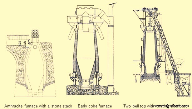
Fig 6 Early blast furnaces
The first important developments in brick making technology did not occur until the 1900s. In 1917, the first machine-made brick was introduced with its resulting increase in density and strength. In 1935, vacuum pressed bricks further improved brick quality. In 1939, super-duty alumina brick containing up to 60 % alumina was first available. In the 1930s, carbon blocks were used in German furnace hearths. Today many varieties of alumina, carbon, and silicon carbide refractories are available for BF lining. The improvements in furnace cooling and lining have increased typical campaign lengths from two years in the 1880s to more than ten years in the 1990s. Today campaign life of BFs has further increased to 20 years.
Another area of the BF which was forced to change with increased production was the casting operation. The old style tymp and dam open front of the furnace was no longer adequate. In 1867, the Lurman front was patented to eliminate the tymp and dam. It consisted of a cast iron panel which was water cooled and had separate openings for iron removal (still known as a tap hole) and for slag removal (known as the slag or cinder notch). This design was changed by the 1880s by rotating the slag notch 90 deg from the tap hole. Both the tap hole panel and slag notch panel were water cooled. By separating these two liquid tapping points, more room was available to set up the furnace for the increasing number of casts required at higher production rates. The area in front of the tap hole was completely available for pig beds while the slag pits were moved around to the side of the furnace (Fig 5). During normal operation, the slag notch was opened with a bar as the liquid slag level approached the tuyeres. The slag was flushed into pits or special slag cars. When the slag notch blew wind out of the opening, it was closed with a manual stopper. By tapping the slag off between iron taps, a greater volume of the hearth was available for liquid iron which resulted in larger cast tonnages. The iron casting process in the 1880s did not change much from previous operations but pig beds were bigger and in 1909 a slag skimmer was installed to skim the floating slag off of the iron as it flowed down the trough.
In 1896, the installation of a pig casting machine invented by EA Uehling finally brought about the complete elimination of the pig bed in the cast house. Next the open-top brick lined ladles were introduced. These ladles carried about 10 tons to 100 tons of hot metal and required the furnace and cast house to be elevated above ground level so the ladles could be placed under the cast house floor. Though the pig beds have got eliminated but troughs and runners remained and spouts going into the ladles were added to the cast house. In 1915, there was first use of the torpedo type ladles. These railroad mounted ladles carried 90 tons but were increased to 150 tons by 1925. Today, the iron ladle design is similar but capacities up to 400 tons are available. Open-type ladles mounted on rail cars are still used today.
Prior to 1890, the tap hole was opened with a bar and sledge hammer. Then in 1890 the first pneumatic rock drill was used. The tap hole was manually stopped with wind off the furnace until 1914 when HA Berg developed the remote controlled mud gun which pushed a clay plug into the furnace with a wind on. In 1906, the first oxygen lancing was used to melt skulls in the tap hole. Modern BFs have evolved to include remote controlled tap hole drills, hydraulic mud guns, cast house slag granulation units and iron tilting spouts to feed an unlimited number of iron ladles. BFs may also have from one to four tap holes and two to six slag pits depending on their size. Removing the bottleneck in the cast house allowed the first 1000 ton/day operation in 1929 and led to 1990s production levels of 12,000 ton/day.
A parallel line of improvement activities which rapidly evolved starting in the late 1800s was iron ore preparation. Iron ore used in iron making consists of many geological forms such as red hematite, specular hematite, magnetite, limonite, fossil ores, bog ores and carbonates. The metallic iron content of these ores ranges from approximately 30 % in the bog ores to 72 % in some hematites. All iron ores are mixed with other compounds in the earth which are undesirable in the smelting process. Beginning in the 1700s, iron ore was roasted with charcoal in open pits or enclosed kilns. The object of roasting or calcining was to liberate all volatile constituents, such as water, carbonic acid or bituminous substances, and to soften and crack the ores, making them more permeable to reducing gases. In the 1800s, iron ore screening was introduced to more closely size the ore for improved gas permeability inside the furnace. At first, hand screening equipment was used but, by the 1870s, steam-driven ore washers consisted of one or two drums that were perforated with holes or slots for the fine material to exit with the wash water while the final sized and washed ore exited the inside of the drum into a wheelbarrow or stockpile.
As iron production increased, the purest iron ores were depleted in many areas so lower grade ores had to be mined. These ores had undesirable impurities and methods to concentrate these ores to higher iron percentages were required. In 1880, Thomas A. Edison obtained a patent for an electromagnetic separator. A demonstration plant was built in Michigan and produced 893 tons of magnetic concentrate in 1889.
Pilot plants to pelletize taconite concentrates were built in 1948. By 1956, two commercial-scale taconite mining and processing operations were producing pellets. The first straight grate pellet machine was made in 1956 and the first grate-kiln pellet machine was put into operation in 1960. Pelletizing technology spread throughout the world from the US. The newest development in pelletizing was the introduction of raw limestone, dolomite or olivine into the pellet to improve its metallurgical properties which, in turn, improved BF productivity and fuel rates.
Iron ore agglomeration also took a separate route from pelletizing earlier in the 1900s. Sintering process originated in the nonferrous industry as a batch process in the late 19th century. Up to the 1950s, most sinter had a basicity ratio of less than 1.0. However, over the next fifteen years, it was realized that a basic sinter with a basicity ratio of more than 1.0 brought a pre-calcined flux source into the BF which resulted in a fuel rate savings.
One of the final technological improvements in iron making over the last 100 years has been tuyere level injectants. The first recorded use of injectant was in 1871 when there was a chilled hearth on the Morgan charcoal furnace. Because blast could not enter the tuyeres due to chilled material, a hole was punched through the furnace wall above the salamander and a large tuyere was installed. Coal oil was then forced under pressure into the tuyere from a pipe running from the top of the furnace. Six days and seven barrels of oil later the salamander had been melted and the furnace was running smoothly. In the first decade of the 1900s early tests with oxygen injection were made in the small BF in Belgium. The first large scale oxygen enriched blast was used in 1951. The benefits of pure oxygen injection are increased BF production due to increased fuel burning capacity and an ability to use more hydrocarbon tuyere injectants. The evolution of hydrocarbon injectant occurred in the 1940s and 1950s. In 1944, William L. Pogue submitted a patent for the use of coal injection. Then in 1953, natural gas injection was implemented. In the early 1960s, injection of oil and tar through lances was developed at numerous steel companies after substantial coke savings were proven by testing in an experimental BF in 1959. By 1967, a large number of the BFs were using some form of fuel (mostly pulverized coal) injection. Today, many BFs use fuel injectants 40 % to 45 % of the fuel rate. The final tuyere injectant, which evolved concurrently with fuel injection, was moisture injection. Historically, hot blast temperatures were limited as excessively high temperature combustion zones resulted in poor burden descent. The injection of moisture consumed coke more rapidly than air alone and produced a gas that was both richer in carbon monoxide and hydrogen and was less dense. These factors improved the rate of heat transfer between gases and solids and the rate of reduction of the burden in the furnace stack, which resulted in a smooth running furnace.
The combination of moisture injection, fuel injection and oxygen injection permitted the increase of hot blast temperature and the use of all of these tuyere level variables further improved productivity and reduced fuel rates in modern BFs.
Evolution of BF iron making as a science
Historically, iron making was more an art than a science. Early iron producers learned their trade through years of training from the previous generation. Many improvements in iron making practice were based on instinct or pure luck. However, by the mid-nineteenth century, science was creeping into the developments in iron smelting.
Charles Schinz of Germany, one of the earliest researchers of chemical and physical phenomena occurring inside a BF, attempted to make quantitative mass and energy balances of BF operation but he was severely limited by the lack of accurate thermodynamic data. He conducted laboratory experiments to determine heat capacity and heats of formation and was apparently the first to determine the reducibility of iron ore. He defined different zones of the BF and the major chemical reactions taking place in each zone. The results of his work were published in 1868.
Several principles which are recognized today were postulated by Sir Lothian Bell, during the late 1800s. He published a book in 1872 which is recognized as the first text book on BF iron making. In 1884, he was seemingly the first to document the function of the different slag components and their effect on melting temperature. He also observed that BF slags are complex structures and there is a range of slag compositions which results in its good fluid properties and desulfurizing capability. His most important contribution was his understanding of chemical reactions. He recognized the importance of CO and CO2, and was the first to start defining equilibrium in the Fe-O-C system. Further, Bell discussed preheating and pre-reduction of iron ores and the importance of the furnace stack where these reactions occurred. He also made carbon, oxygen and nitrogen balances of the BF operations and showed that some of the charged carbon was consumed in the stack by CO2 in the ‘solution loss’ reaction.
A contemporary of Bell was ML Gruner, a professor of metallurgy in France, further expanded Bell’s methods of determining BF heat balances by comparing many different furnace operations. He also believed that the minimum fuel rate for BFs would be achieved when solution loss was eliminated.
JE Johnson, Jr. was the first American scientist to explore the BF process and published two books on BF design and operation in the early 1900s. He applied the first and second laws of thermodynamics to iron making and explained how fuel rate was impacted by blast temperature. He postulated that there was a critical furnace temperature above which a minimum amount of heat is required. This minimum amount of heat he called ‘hearth heat’. In his book, published in 1913, Johnson produced a diagram showing chemical reactions and isotherms in the BF. The application of the critical temperature and hearth heat concepts further convinced furnace operators that the BF process was rational and predictable.
During the period from 1920 to 1930, the flow of solids and gases in the BF was studied extensively by a group of workers named PH Royster, SP Kinney, CC Furnas, and TL Joseph. This group was interested in physical and chemical phenomena occurring in BFs and in order to understand these phenomena they felt it was necessary to sample and probe operating furnaces. Their work started with a small experimental BF and spread to commercial furnaces. The results of their studies showed that the flow of gases and solids was not uniform across any horizontal plane in the BF and that improving gas-solid contact in the stack of the furnace could significantly increase the efficiency of the iron making process. Furnas and Joseph continued this work and determined that raw material size and reducibility was critical in gas-solid reactions. This important work led to the understanding of burden distribution and the optimization of iron ore sizing as it impacts both reducibility and permeability.
In 1962, R. Stephenson explained the role of solution loss. Previously, it had been thought the production of CO by reacting with CO2 and carbon was a waste of fuel. Stephenson pointed out that iron oxide reduction is a combination of indirect reduction and direct reduction and that indirect reduction followed by solution loss is direct reduction. Using these considerations to determine carbon rates for all combinations of these two reduction routes as a function of solution loss, results can be plotted on the ‘carbon-direct reduction diagram’. In the 1960s and early 1970s, the best applications of these BF theories were put into practice in Japan. Currently, the Japanese improvements have spread in the form of large, highly automated BFs to other places.
The theory and practice of iron smelting technology have come a long way in the last 4000 years. The transition from sponge iron produced in forges to liquid iron produced in BFs in the 1300s was the first major step in advancing iron making technology. Then came the change from cold blast, charcoal furnaces to hot blast, coke furnaces in the mid-1800s which brought iron making into the modern era. The better understanding of iron making reactions and improved equipment evolved into the hard-driving furnace operation centered in the 1880s to 1900s. Finally, the revolution in scientific applications to iron smelting, the installation of more sophisticated equipment, and the advent of electronically controlled systems has accelerated BF iron making into the current state as demonstrated by the operation of around 12,000 tons/day BFs with fuel rates less than 460 kg/ton.
制造工艺