

铁矿石烧结理论与实践
铁矿石烧结理论与实践
铁矿石烧结是一个通用术语,用于描述铁矿石粉、熔剂、燃料(焦炭粉)和工厂返回细粉(例如轧机氧化皮、高炉粉尘)的烧结混合物(原料混合物或生混合物)的过程, 和返回的烧结细粉等) 被转化为特定形式的团块。它包括将粒度小于 10 毫米的烧结混合物加热到使炉料混合物的每个晶粒表面开始熔化并且形成的熔体在晶粒之间形成液体桥的温度,从而确保在凝固后形成一种称为烧结体的固体多孔材料,筛分尺寸通常为 5 毫米至 30 毫米(根据当地要求,筛分尺寸可达到 50 毫米),并且可以承受高炉 (BF) 内的操作压力和温度环境。
烧结过程是涉及熔化和同化反应的热操作。烧结过程的第一阶段是熔体的形成,其中涉及细铁矿石颗粒和熔剂之间的反应。初始熔体是在加热过程中通过铁矿石和熔剂之间的反应由粘附的细粉产生的。然后,核粒子被部分同化或溶解到初级熔体中,形成更多的熔体。在完全熔化之前,由于在最高温度下停留时间短,烧结温度下降,然后熔体凝固,矿物相沉淀,形成结合相。
在烧结过程中,在高温下发生化学反应,铁矿石和熔剂结合在一起,形成由铁矿石、钙铝硅铁氧体 (SFCA)、硅酸二钙和玻璃相组成的烧结饼。 .烧结反应还可以调节每种矿物的体积分数,从而影响烧结矿的质量,进而影响高炉的性能。
烧结的第一阶段是烧结混合物的造粒(球化或粒化),包括在混合鼓中将其均质化几分钟并添加 6% 至 8% 的水。然后将粒状烧结混合物装载到可渗透的烧结条炉篦上。床顶被气体燃料加热到高温,空气通过炉排被吸入。在短暂的点火时间后,停止加热床顶,狭窄的燃烧区或火焰前锋 (FF) 向下移动穿过床,依次加热每个床层。在床中,颗粒被加热到1250℃至1350℃的温度范围以实现它们的软化,然后部分熔化。在一系列反应中产生了一种半熔融材料,在随后的冷却中结晶成几种不同化学和形态组成的矿物相。
在烧结过程中,焦炭的燃烧产生了一个高温区(燃烧区),该高温区通过烧结床向下移动。细颗粒反应较快,形成初级熔体,部分溶解粗矿颗粒。断续烧结过程的烧结床横截面示意图如图 1 所示。焦炭燃烧的进程决定了温度分布和床中不同区域的形成。随着燃烧区向下移动,通过空气吸入发生熔化相的凝固,从而形成烧结区。燃烧区下方的区域由烧结混合物(未反应的材料)组成,可以分成两个区域。燃烧区正下方的区域对应于烧结混合物被燃烧区的热气脱水,而该区域下方的区域是烧结床的冷部分,蒸汽被冷凝。
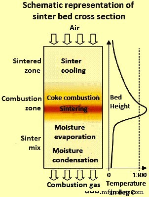
图1烧结床横截面示意图
原则上,烧结反应涉及细矿石与熔剂的反应,导致形成熔融相,该熔融相在固-液反应期间用于同化粗矿石。在烧结过程中形成的熔体充当粘合相。由于 SFCA 因其在烧结矿中的丰富性及其对烧结矿质量的显着影响而被认为是结合相中最重要的成分,因此专门研究了烧结反应,以控制在烧结过程中形成的 SFCA 相的浓度和微观结构。烧结过程。熔融相的体积在烧结过程中起主要作用。过度熔融导致玻璃状结构均匀,还原性低,而非常低的熔融浓度导致烧结矿强度不足,导致大量返矿。
工艺能量由焦粉燃烧提供。在燃烧区之前,水蒸发,挥发性物质被驱走。在燃烧区,发生反应,形成坚固的烧结物。离开燃烧区的气体产生的大部分热量被吸收用于床层下层的干燥、煅烧和预热。当燃烧区到达床底时,整个过程就完成了,热烧结饼从炉排上倾倒出来,在热破碎机中粗略破碎。
烧结是一个连续的过程。烧结带由一系列托盘组成,每个球团都有侧壁和可渗透的炉排,其中装有烧结混合物,通过点火罩下方,受到下吸风,倾翻,然后返回到装载位置。钢绞线下方的风箱通过气体净化系统与风机相连。
烧结混合料
形成烧结床的烧结混合物主要由铁矿石、焦粉、熔剂和返回细粉组成。烧结过程中烧结矿混合物的行为和烧结矿的质量很大程度上取决于铁矿石的化学、粒度和矿物学成分。矿石特性影响烧结行为,因此它是烧结矿生产的一个重要方面。已经对烧结混合物成分对烧结相的影响进行了各种研究,这反过来又会影响碱度(CaO/SiO2)、温度、热状态以及 Al2O3(氧化铝)和 MgO(氧化镁)含量对铁素体含量的影响,总赤铁矿、磁铁矿氧化再氧化赤铁矿、还原性指数(RI)、还原降解指数(RDI)和翻转指数(TI)、孔隙率和结焦率。
烧结过程中烧结混合物的行为取决于其化学成分。为了检验烧结混合物的化学成分对熔体形成和同化反应的影响,已经进行了几项研究。铁矿石化学成分的微小变化可以引起烧结过程中相形成的显着改变。
烧结矿质量取决于结合相的形成,而结合相又取决于铁矿石的烧结能力。另一方面,铁矿石的反应性受其粒度的显着影响,这决定了烧结混合物的反应表面积和堆积密度(孔隙率)。因此,铁矿石的粒度对于控制烧结过程中的烧结反应很重要。
矿石粒度的变化影响烧结过程。已经发现,细矿石颗粒的同化能力大于粗颗粒。细颗粒的反应表面积大,导致高反应速率。然而,较高浓度熔体的形成会导致熔体粘度增加,从而导致熔体流动性下降。因此,在烧结混合物中加入粗颗粒对于提高烧结床的渗透性是必要的,这与熔体和固体颗粒之间的大规模运动增加有关。
铁矿石平均粒度影响烧结床的渗透性,进而影响烧结矿的微观结构和生产率。较大的颗粒有利于扩散结合,而较小的颗粒有利于烧结过程中的熔渣结合。高比例的小颗粒形成过多的熔体,导致烧结矿质量劣化,而大量粗颗粒形成的烧结矿导致烧结矿强度下降。研究发现,铁矿石平均粒度的增加提高了烧结矿的生产率。
在对掺入大颗粒的烧结床的可烧结性进行研究期间,发现使用较大的矿石颗粒会提高烧结床的渗透性以及工艺过程中的烧结反应。当大颗粒放置在床中时,颗粒周围会形成低密度区域。由于烧结床渗透性的增加,气体流速以及 FF 速度在大颗粒周围高于细颗粒。因此,由于熔体的高流动性,大颗粒周围可以迅速发生熔体反应和同化。
粒度分布也影响压实球团的堆积密度,从而影响烧结速率。由细颗粒组成的混合物的填充密度通过用粗颗粒代替其中一些来提高。在压实过程中,固体颗粒可以靠得更近,从而导致颗粒之间的大量接触和高堆积密度(低孔隙率)。用大颗粒代替细颗粒导致填充密度增加到最大值,之后随着粗颗粒的较高比例降低。最大填充密度出现在粗颗粒之间的所有空隙都被小颗粒填充的点。因此,粗颗粒的存在可以产生具有更高填充密度(更低孔隙率)的压实粉末,从而提高烧结率。
矿石混合物中的超细粉含量,特别是负 50 微米(微米)细粉部分,在造粒中起着至关重要的作用,首先是在核心颗粒周围开始形成涂层,然后将较大的颗粒粘合在一起。尺寸与涂层的粘附细粒。
焦炭是铁矿石烧结的最佳燃料。尺寸分类是一个关键因素。焦炭粒径小于 3 毫米时可实现最佳经济性和效率。一些研究表明,烧结矿生产率和还原性的最佳焦炭尺寸在 0.25 毫米和 3 毫米之间。另一项研究表明,尽管焦炭尺寸小于 0.25 毫米会对生产率产生负面影响;它不影响燃烧过程的效率。此外,较粗的部分是优选的并且在消耗方面更经济。不同焦粉粒度级分的比较表明,使用粗焦(小于 3 毫米和大于 1 毫米)比使用细焦(小于 1 毫米)获得更好的结果。细焦主要被认为是在颗粒周围形成表面涂层的颗粒中的粘附细粒。细焦燃烧较快,而粗焦燃烧较慢并且会扩大 FF,从而可能导致生产力损失。此外,粗燃料更经济,可以提高烧结矿产量,提高 RDI 并降低 SO2 排放。
在烧结罐试验中研究了烧结床中焦炭粒度对生产率、焦炭消耗和烧结矿质量的影响。这些测试表明,较粗的焦粉馏分导致更高的 FF 速度和更好的燃烧效率。细焦的燃烧效率较差,产生的热量较少,烧结温度较低。因此,为了保持烧结矿质量,需要在使用细焦时提高焦炭率。
烧结混合料的造粒
造粒的目的是使细颗粒相互粘附,形成较粗的颗粒。因此,粒状矿石的粒度范围较小,因此对气体通过的阻力较小。
造粒对于铁矿石的烧结至关重要,因为良好的烧结床渗透性在很大程度上决定了工艺进行的速度,从而决定了烧结厂的生产率。烧结混合物的造粒通常在烧结过程之前在转鼓中进行几分钟,同时添加 6% 至 8% 的水。完整的造粒过程大约需要30分钟到1个小时,包括加湿、造粒和插入烧结机。
新日铁公司 (NSC) 对粒状烧结混合物的结构进行了初步研究。这些研究创造了术语“准粒子”,有时也称为伪粒子(图 2),它由铁矿石核组成。在烧结过程中,这种准颗粒保持部分未熔化,被更细的带有二氧化硅(SiO2)脉石的矿石颗粒包围,并且存在高碱度(CaO/SiO2)。
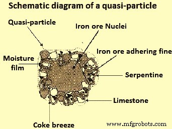
图2准粒子示意图
在造粒过程中,当细颗粒(小于0.2毫米)附着在大颗粒(大于0.7毫米)的表面形成颗粒时,形成准颗粒。中间颗粒(0.2 毫米至 0.7 毫米)难以造粒,没有明确的作用。在实践中,由于中间颗粒对造粒的不利影响和对烧结床渗透性的不利影响,需要尽量减少中间颗粒的量。烧结混合物中水含量的增加会导致中间颗粒充当粘附细粒,这些细粒难以粘附到粗粒上,并且可能在干燥阶段脱落。中间粒子也可以作为核并形成与具有较粗核形成的那些相比具有较小尺寸的准粒子。这会显着降低烧结床的渗透性以及烧结过程的生产率。
在烧结过程中,由于赤铁矿与含有少量 SiO2 和 Al2O3 的 CaO-Fe2O3 熔体发生固液反应,铁氧体会在附着在晶核上的层中形成。可用于制粒的水分高度影响粘附力。其他因素如原子核的性质、粒子的形状和表面性质是次要的。
待烧结的烧结混合物中的水分含量是造粒过程中非常重要的参数。将细颗粒粘附到晶核以形成准颗粒的过程受到可用于造粒的水分(总水分减去烧结进料组分吸收的水分)的强烈影响。最大产量是通过最佳水分添加来实现的,这低于最大透气性所需的水分。正常运行在最大渗透率所需值的 0.85 倍左右。这是因为随着 FF 的接近,水分从上部蒸发后在床的底层凝结。冷凝通常发生在烧结的前 2 分钟,在烧结混合物达到其露点温度之前。
对水分添加的良好控制是必不可少的。需要调整搅拌筒中的加水量以保持设定的水分水平。手动方法需要自动控制,因为它可以确保更快速的响应和更一致的烧结线给料。
通过在转鼓中滚动材料进行的造粒通过粘附增加颗粒尺寸,这主要是由于两种力的作用,即(i)颗粒的“互锁”,和(ii)通过产生的吸引力颗粒之间的液相“桥梁”。可以通过改变待烧结混合物的形成顺序来改变联锁力大小的重要性,从而有利于给定成分(例如返回的烧结细粉)提供的粒化核的聚集作用。
联锁力的大小也可以通过修改烧结混合物的形成顺序来改变,以包括选择性造粒或预附聚过程。在这种情况下,这涉及使用额外的工艺线分别处理矿石细粉和精矿,一些返回的烧结细粉和石灰。这些材料与水混合并在转鼓或圆盘中进行微粒化,然后在造粒转鼓之前引入主造粒回路。在这个过程中,返回的烧结细粉充当核心,石灰充当凝聚剂。这种做法可以在不损失生产力的情况下使用更多的细粉。
后一种力(桥梁)是由添加到混合物中的水产生的,并且它们的效果可以通过使用添加剂来增加。在这两种情况下(互锁和桥接),粒状颗粒的强度都不高。仅确保粒状混合物可以在烧结炉篦上运输和分层而不会破裂就足够了。将粒状混合物送入烧结炉篦子时,其粒度分布范围为 1 mm 至 10 mm。
在三维图像中找出颗粒结构的研究通常使用 3D X 射线断层扫描技术来完成。在一项这样的研究中,铁矿粉(精矿)、返回的烧结矿粉和石灰石的混合物以 20:80、50:50、80:20 和 100:0 的精矿/矿石比制备,并且生产的烧结矿的碱度为0.8、1.4 和 2.0。在烧结混合物中加入更多的精矿使造粒变得更加复杂。
超细颗粒不仅能附着在粗颗粒上,还能在结合中等尺寸颗粒的同时形成耐久的晶核,而且在烧结混合物中使用的超细颗粒越多,颗粒的尺寸分布就越难以预测。属于不含粗矿的烧结混合物(精矿/矿石比为100:0)的颗粒没有晶核,很少有石灰石颗粒粘附在最初由球团机制形成的表面,并呈现出与球团相似的结构。造粒行为不能用任何一个单一的因素来完全解释,例如精矿/矿石比,矿石矿物学、脉石的组成和数量、热消耗和混合物中的水分含量的变化,都是非常相关的因素。
烧结矿生产率与床层渗透率直接相关。反过来,渗透性与颗粒尺寸分布和平均颗粒尺寸有关,这取决于水分的添加。作为水分的函数,渗透率上升到最大值。由于床层底层的水分凝结,使用最大渗透性所需的 85% 的水分可获得最大生产率。
在为预测许多不同性质的铁矿石的造粒行为而进行的一些研究中,提出了一个方程来计算原料混合物的最佳水分,作为铁矿石的性质、成分和粒度的函数。矿石。最佳水分含量定义为达到最大床渗透性所需的最低量。该方程式适用于每种矿石和矿石混合物,并添加了焦炭、熔剂和返回的烧结细粉。实验值与计算值具有良好的相关性。
在其他一些关于造粒的研究中,设备被设计用来确定几种类型的铁矿石和矿石混合物的水分容量。含水量被定义为矿石颗粒之间可以保留的最大含水量。可以看出,水分容量随着外表面积的增加而增加,随着矿石孔隙体积的增加而减少。确定最佳水分 (W) 和水分容量 (MC) 之间比率的公式是 W =6.94 + 0.12 MC。实验数据表明W和MC之间有很高的相关性。
基于进一步的研究和初步研究,已提出的计算最佳水分 (W) 作为铁矿石性质、成分和粒度的函数的公式为 W =2.28 + 0.427 L + 0.810 A – 0.339 S + 0.104D + 0.036 E 其中 L 是矿石在加热过程中的失重,单位为克,A 是矿石中 Al2O3 的百分比,S 是矿石中 SiO2 的百分比,D 是小于 0.2 mm 的矿石粒度分数,E 是矿石粒度分数在 0.2 毫米和 1 毫米之间。已经确定,具有更高水分容量的样品需要更高的水分含量才能实现最佳的床渗透性。将渗透率与矿石性质直接联系起来是不可能的。
还进行了研究,通过确定氧化铁与水之间的接触角和铁矿石造粒适应性来确定水分添加和润湿性对造粒的影响。该研究考虑了不同类型的矿石以确定各种参数之间的相互作用,即(i)矿石性质(孔隙度),(ii)水分含量,(iii)润湿时间,(iv)矿石-水接触角的测量,(v)表面粗糙度,(vi) 造粒滚筒的 rpm,(vii) 细颗粒的粘附细率 (AR),和 (viii) 准颗粒的断裂强度 (FS)。针铁矿矿核的造粒效果最好,具有高孔隙率、低粗糙度和低接触角(更湿润)。
一些烧结厂也使用了两阶段造粒系统。两级造粒系统有助于处理细矿石,同时提高工艺的FF速度、渗透率和生产率。
改进传统的造粒工艺是有利的,特别是当使用针铁矿和褐铁矿时,这些矿石通常比赤铁矿具有更高的 Al2O3 含量并导致烧结物性能劣化。在这方面,研究表明,当滚筒混合机中的常规造粒阶段之后是第二阶段时,烧结矿质量会提高。在第一阶段,铁矿石和返回的烧结细粉的混合物被放入转鼓中。在第二阶段,将焦炭、石灰石和白云石添加到由第一阶段产生的混合物中,所获得的颗粒由主要由铁矿石组成的核形成,并被焦炭和熔剂包围。由于石灰石中的 CaO(氧化钙)与铁矿石中的 Fe(铁)分离,这种涂层造粒工艺改善了熔剂形成反应。这导致在较低温度下进行烧结,提高了渗透性和生产率,并减少了二次赤铁矿的形成,从而提高了 RDI。由于形成了更多的微孔,TI 和还原性也得到了改善,这也防止了导致 RDI 劣化的裂纹的扩展。
第二阶段转鼓中的混合时间非常重要,已将 50 秒左右确定为最佳时间。较短的时间不允许核被焦炭+助熔剂很好地覆盖。较长的时间会导致准粒子的破坏,因为在(核的)颗粒中包含焦炭和熔剂,并产生与单级常规造粒中获得的准粒子相似的准粒子。
已经对焦炭和石灰石涂层造粒方法进行了详细研究,目的是提高生产率、还原性和高炉操作。该技术包括将焦炭和石灰石涂覆在已在滚筒混合器的主要部分中造粒的准颗粒的表面。焦炭和石灰石由带式输送机从鼓式混合机末端高速注入,以实现对准颗粒的包覆。包衣造粒时间是最重要的控制因素,可通过改变输送机速度进行调整。正常时间在40秒到60秒之间,时间越短,准粒子未全部被包覆,时间越长准粒子被破坏。
还进行了研究以评估单独造粒的颗粒(焦炭涂层和石灰石涂层)的偏析,并且在两种造粒情况下,与传统生产率相比,生产率都有所提高。焦炭涂层改善了准颗粒的内聚应力,从而改善了湿区的渗透性。使用石灰石涂层的烧结矿呈现出较低的二次赤铁矿含量和具有抗裂性(改进的 RDI)、更多的原生赤铁矿和 SFCA(改进的 RI)以及改进的熔体流动性的结构。高炉竖井效率提高1%,还原剂用量可降低7公斤/吨铁水。
日本的一些烧结厂也采用了选择性造粒技术。该技术用于烧结高 Al2O3 含量的铁矿石,否则由于 Al2O3 轴承材料的低反应性和初级熔体的高粘度而难以烧结。选择性造粒包括筛选矿石并将具有较低 Al2O3 含量的较大尺寸部分送至常规造粒回路,而将具有较高 Al2O3 含量的较小尺寸部分造粒成尺寸为 2 毫米至 5 毫米的颗粒,并加入到常规造粒回路。较小尺寸的部分包含粘土矿石,其 Al2O3 含量高,需要较高的熔化温度。选择性造粒获得了比常规造粒具有更高Al2O3含量的粒核。在此过程中,细粉通过与石灰石反应而附着在Al2O3含量较低的晶核上,促进了较低温度的初生熔体的形成。
选择性造粒工艺原料处理率高,可连续处理粘性原料。此外,实现了燃料焦炭减少和鼓风机功率减少。此外,提高了生产率并降低了FeO含量。还原性的提高反过来导致高炉中焦炭消耗的减少。烧结矿的RDI值也有所提高。
火焰前端
火焰前沿或燃烧区温度对烧结时间和生产率有非常大的影响,因为它对 FF 渗透率有影响。通常,FF 温度的降低对生产率非常有利,因为 FF 对气流的阻力是气体速度的 3 次方的函数。提高 FF 温度会显着增加气流阻力并导致烧结时间增加并降低生产率。测量烧结床中不同水平的温度可以监测燃烧区的运动,并将 FF 速度的概念定义为温度升高最快的水平通过床的速度。图 3 显示了理想的烧结床温度(热量)分布。
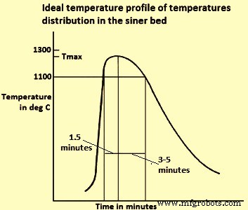
图3理想的烧结床温度分布
高温区(高于 1100 摄氏度)的加热时间需要较短(1.5 分钟),因为该区的氧分压测量值 (pO2) 由于焦炭燃烧和 FeO 较低,这对烧结矿的还原性有害, 很容易形成。冷却时间(至 1100 摄氏度)需要很长(从 3 分钟到 5 分钟),以便通过形成脉石基质来实现坚固的烧结结构,这有利于 SiO2(二氧化硅)的存在。在床的几个位置测量了时间-温度曲线,表明燃烧区的宽度和Tmax随着它下降通过床而增加。
为了达到均匀的 Tmax,在一些烧结厂中进行了两层烧结。它包括在上层制备焦炭含量高于下层的床,以抵消 Tmax 升高的趋势。除了控制床中热量分布的两层外,还开发了连续测量设备,直接发出整个床的温度分布信号,以及测量通过烧结炉排吸入的体积分布的装置。热分布可以通过调整拉坯速度和烧结混合物中的焦炭含量来控制。
最大 FF 温度与烧结矿结构之间存在关系。当在低于 1300 ℃的温度下进行烧结时,在 1200 ℃左右,在烧结床中产生熔体(主要由 Fe2O3 和 CaO 组成),氧化铁和细颗粒在熔体中同化。如果熔体渗入赤铁矿晶粒,则会发生界面破坏,留下初级赤铁矿(未熔化),这被认为有利于烧结,因为它提高了 RI。当 CaO 和 Al2O3 在熔体中同化时,它与氧化铁反应生成针状铁酸钙(尺寸小于 10 微米),其中含有 Al2O3 和 SiO2 作为固体溶解物,根据一般反应 Fe2O3 + CaO + SiO2 + Al2O3 ? SiO2·CaO·(Fe, Al)2O3。钙铝硅铁氧体(SFCA)具有良好的还原性,赋予烧结体机械强度,提高破碎指数(SI)和翻转指数(TI),被认为是对烧结体结构非常有益的成分。
在低温(低于 1300 摄氏度)烧结过程中,磁铁矿的形成减少(FeO 减少),并且烧结提高了 RI 并降低(提高了)RDI。此外,在 BF 中实现了烧结体还原性的最佳结构,它由被针状铁素体晶格包围的赤铁矿核(未熔化)形成。当在高于1300℃的温度下烧结时,部分铁素体溶解并熔化,转化为赤铁矿或磁铁矿,并转化为脉石成分。 When the melt cools it forms as new phases of (i) large ferrite crystals, whose reducibility is inferior to the acicular ferrite, and (ii) secondary hematite, which is detrimental to the RDI. Fig 4 illustrates schematically the development of the different structures of sinter as a function of the Tmax reached in the bed.
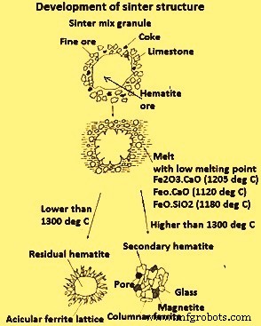
Fig 4 Development of sinter structure
Tab 1 shows the variance of the phase composition and sinter quality indices as a function of the temperature Tmax.
| Tab 1 Typical values of phase composition and sinter quality at maximum temperature in the bed | ||||
| Subject | Unit | Tmax in deg C | ||
| Around 1200 | Around 1250 | Around 1300 | ||
| Primary hematite | % | 50 | 42 | 22 |
| Secondary hematite | % | 5 | 5 | 20 |
| Magnetite | % | 10 | 15 | 20 |
| SFCA | % | 35 | 38 | 30 |
| Glass+2CaO.SiO2 | % | 7 | 10 | 12 |
| FeO | % | 35 | 30 | 15 |
| Porosity | % | 3 | 4 | 5.5 |
| RDI | % | 30 | 32 | 36 |
| Reducibility index | % | 72 | 70 | 64 |
| Shatter index (SI) | % | 93 | 94 | 95 |
The best results are obtained in the temperature of around 1250 deg C, with a maximum percentage of ferrites, high primary hematite, low secondary hematite, good porosity, and good quality indices (FeO, RDI, RI and SI).
Softening and melting of sinter in BF
The BF operation is dependent upon the geometry and condition of the cohesive zone, which is limited by the softening (ST) and melting (FT) isotherms. The cohesive zone is constituted by alternate layers of soft sinter and coke. The latter (known as ‘coke window’) allows the reducing gas to pass through to the BF shaft. Hence, it is important for the cohesive zone to be as narrow as possible, in order to facilitate the penetration of the reducing gas, and as low as possible in the BF, so that the furnace preparation zone above the cohesive zone is sufficiently large to allow the reduction of iron oxides. In order to fulfill both conditions the ST and FT is to be as high as possible and the difference between them is to be minimal. Part of coke consumption saving in BF takes place due to the improved sinter quality, in particular its reducibility and high temperature properties.
Several studies have been carried out into the fundamental mechanism underlying the softening and melting of the sinter in the BF. The sequence which takes place during softening and melting consists of (i) pre-softening, (ii) softening, (iii) exudation, and (iv) dripping stage. The softening mechanism is related with the melting rate of the core as a function of the temperature. Deformation is considered to be directly related with the macro-porosity generated by the transfer of melt from the core to the outer layer. Initial melt formation plays a role in the start of softening, reduction, retardation and dripping of melt from the bed.
In one of the studies in an experimental unit which reaches a maximum temperature of 1400 deg C, the softening and melting of sinters has been determined for different basicities (range 1.5 to 3.0), MgO contents (range 3.3 % to 10 %) and many sinter reducibility grades. The softening-melting range has been defined as the temperature range between the point of reversal (T1 softening) and 10 % contraction (T2 melting). It has been noticed that the behaviour of BF improves (lower and narrower cohesive zone) as the sinter/ore ratio in the BF charge increases.
Another study done for finding the effect of the FeO content in sinter (sinter type A 10 % and sinter type B 12 %) on softening and melting, and its impact on the BF working. The sinter with more FeO caused early softening of the burden, a phenomenon which is undesirable in the BF. Unreduced FeO is reduced at a higher temperature, according to the equation FeO + C =Fe + CO, and such direct reduction in a higher amount leads to a higher coke rate in the process. A lower wind volume, production and productivity have also been noticed in comparison with the behaviour of BF when operating with a sinter load with 10 % FeO. A drop in the MgO content in sinter from 1.75 % to 1.5 % gives rise to changes in furnace behaviour which is attributed to variations in the softening and melting temperatures.
Another study has been carried out to find the influence of the material composition on softening and melting properties in the BF burden materials. The experimental part has been carried out in a unit which simulates BF environment, operating under load up to a temperature of 1580 deg C. Sinter showed a high softening temperature (around 1400 deg C) but a relatively low meltdown ratio and poor high temperature permeability. An increase in sinter basicity has been seen to be detrimental to the fluidity of melted slag and iron in the BF, resulting in more melted slag and iron being blocked in the coke layer, thus decreasing the percent meltdown and increasing the gas resistance of the sample bed. For this reason it is important to lower the sinter basicity. On the other hand, an increase in Al2O3 (range from 0.9 % to 2.6%) or MgO lowered the slag melting point, thus favouring a reduction in high temperature gas resistance. Sinter presents better softening and melting behaviour than pellets or ore, but worse meltdown and high temperature gas resistance. It has been seen that a mixed burden containing 65 % sinter, 20 % lump ore, and 15 % pellets is slightly better than other compositions in terms of FT and ST, meltdown and high temperature gas resistance.
In an another study it has been found that the softening temperature comes down as the gangue content in the ore increases, due to the fact that gangue forms compounds with low melting point such as 2FeO·SiO2, FeO·SiO2·CaO, and Fe2O3·SiO2·CaO (Fig 5). The alkalis contained in gangue can also form compounds with a low melting point such as Na2SiO3, K2SiO3, and NaAlSi2O6. The softening temperature of the sinters produced at temperatures between 1300 deg and 1350 deg C depends on the composition and mineralogy of the sinter.
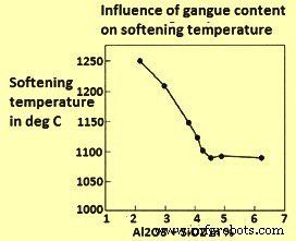
Fig 5 Influence of gangue material on softening temperature
The permeability resistance K of the sinter bed is generally evaluated by the sinter softening property test. When K is plotted against the bed temperature, integrating the curve obtained in the 1000 deg C to 1600 deg C interval, the KS bed resistance parameter when calculated, it has been found that a reduction in the SiO2 content and an increase in MgO in sinter improves both its permeability (lower KS) and the sinter softening property. The action of SiO2 is due to a decrease in the melt which fills the voids in the bed. The action of MgO is due to an increase in the melting point of CaO-FeO-SiO2 slag. The Al2O3 content has little effect on the sinter softening property.
In another study, it has been found that as the sinter is improved when the Al2O3 content is decreased from 1.8 % to 1.5 %, the sinter has better reduction and softening-melting in the BF. Also the permeability resistance index in the cohesive zone is improved. This may be due to the amount of melt having low melting point being little owing to the improved reduction efficiency and lower Al2O3 content.
The softening and melting behaviour of three lump hematite ores and a sinter has been determined in an outfit which operates under load. It has been found that the beds of lump ores contract much earlier than sinter by the formation of fayalite, with a low melting temperature component to be around 1175 deg C to 1205 deg C. No fayalite forms in sinter and at higher temperature melts which are generated appear to be more viscous, resulting in less bed deformation. There is not an appreciable difference for the softening and melting temperatures for sinter and for 80 % sinter and 20 % lump ore blend. With this blend as ferrous burden in the BF, the permeability remained in the normal operating range, the same that when the BF operate with 100 % sinter, with no indication of non-uniform gas flow conditions or abnormal cohesive zone issues and gas utilization efficiency even improved slightly.
An important property of melts is that they coalesce, transforming the uniformly packed bed of granules into sinter particles and very large channels in the bed. The coalescing behaviour of melts needs to have a favourable influence on the flame front properties in determining the permeability of the sinter bed.
Reactions in the process of sintering
During the sintering process, several chemical reactions between iron ores and fluxes are taking place at a specific maximum temperature, resulting in conversion of loose materials into a solid mass. These reactions are defined as sintering reactions and involve the formation of the melting phase followed by the assimilation of large particles into the melt.
Studies have been carried out regarding the sequence of formation of phases during iron ore sintering (Fig 6). These studies found that the sintering reactions occurred in the FF and consisted of reactions between a fraction of iron ore and the principal flux. This led to the formation of a liquid phase which formed the bonding phase. It has also been that the sintering reactions start within the layer of adhering fines where fine reactive ores and fluxes are in intimate contact. Hence, solid – solid reactions are the first reactions to occur, generating the primary melt. However, large particles are almost inactive during this first stage due to their large reaction area.
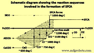
Fig 6 Sequence of formation of phases during iron ore sintering
The sintering reactions consist of melt formation and assimilation reactions (Fig 7). A relevant starting point was a pseudo-particle consisting of a large core particle (nucleus) and a coating layer of adhering fines and fluxes. Fig 7 (i) represent the basic structure of pseudo-particles formed during the granulation. The sintering reactions begin within the layer of adhering fines, where fine materials are in intimate contact. With the increase in temperature (at about 1100 deg C), calcium ferrites are the first product to form by solid-solid reactions between hematite and lime. At around 1200 deg C, calcium ferrites decompose and form the initial liquid melt, which can dissolve SiO2 and Al2O3. This stage of the sintering process is schematically represented in Fig 7 (ii). As the sintering process progresses, the liquid melt starts reacting with the nucleus particles, resulting in a dissolution of the nucleus particle and formation of more melt as shown in Fig 7 (iii). The assimilation reaction depends on the properties of both the initial melt and nucleus particle. The more reactive is the melt, the greater is its ability to dissolve the solid nucleus. Similarly, the greater is the reactivity of the solid nucleus, the more is the amount which gets assimilated.
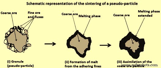
Fig 7 Schematic representation of the sintering of a pseudo-particle
In principle, the sintering reactions involve reactions of fine ores with fluxes resulting in the formation of a melting phase which is used during solid-liquid reactions for the assimilation of coarse ore. The melt which forms during sintering acts as the bonding phase.
During the sintering process, the formation of the melt occurs in the FF where the temperature is higher than 1100 deg C. Then, the melt solidifies to become the bonding phases which make up the majority of other phases within a sinter. The bonding phase is generally consists of the SFCA phase in association with iron oxides and silicates. SFCA is considered to be the most important bonding phase because of its great influence on the properties of sinter.
In the process of sintering the temperature of the sinter mix is increased to achieve its partial melting and to produce a molten material which, during cooling, crystallizes or solidifies into several mineral phases which agglomerate the structure as a whole. The energy for this process is supplied by burning of the coke breeze.
A study to determine the sequence of reactions in SFCA formation has been carried out using a combination of XRD (X-ray diffraction), DTA (differential thermal analysis), and EPMA (electron probe micro analyzer). The first ferrites formation reactions are solid-solid reactions which start in the temperature range of 750 deg C to 780 deg C and end at 1200 deg C, the melting temperature of these ferrites, following the sequence dicalcium ferrite (C2F) to calcium ferrite (CF) to calcium diferrite (CF2) (Fig 6) as per the following equations.
Fe2O3 + 2CaO =2CaO·Fe2O3 at 750 deg C to 780 deg C
2CaO·Fe2O3+Fe2O3 =2[CaO·Fe2O3] at 920 deg C to 1000 deg C
CaO·Fe2O3+Fe2O3 =CaO·2Fe2O3 at 1050 deg C to 1150 deg C
CaO plays an extremely important role during sintering as it combines easily with Fe oxides in the mix to produce calcium ferrites. The melt formation reaction starts at the point of contact between the ore fines and CaO. At the same time, the solid-solid SFCA formation reaction starts at around 1050 deg C and continues in a solid-liquid reaction above 1200 deg C. The presence of Al2O3 increases the stability of SFCA, and lowers the temperature at which these ferrites start to form. Above 1200 deg C, solid-liquid (solid-melt) reactions predominate, with the presence of a molten phase which reinforces the assimilation of material to form ferrite as per the following equation.
CaO·Fe2O3 + Al2O3 + SiO2 =CaO·SiO2·(Fe, Al)2O3
The sequence of SFCA formation reactions is shown in the schematic diagram (Fig 5). Al2O3 is highly reactive and enters the solid dissolution with the C2F, CF and CF2 phases, as indicated in the shaded region of Fig 5. In this study it has been also seen that SiO2 does not react with Fe2O3 or CaO and remains inert until SFCA start to form at temperatures higher than 1050 deg C.
Study has also been done on the formation of 2CaO·Fe2O3 at 1000 deg C from a stoichiometric mixture of Fe2O3 (Fe ore) and CaCO3 (lime stone). Fe2O3 is reduced to Fe3O4 and FeO before the calcination of limestone starts, as a function of the partial pressure of O2, which is determined according to the CO content in the CO+CO2 reducing mixture. The order which is found for the reaction rate of Fe oxide with CaO, for the formation of dicalcium ferrite is FeO -> Fe3O4 -> Fe2O3.
Throughout the process, the Fe oxide can simultaneously be reduced by CO produced in the partial combustion of coke-coal as per the following equation.
2 Fe2O3 + CO =Fe3O4 + FeO +CO2
Fe3O4 can oxidize to Fe2O3. FeO can oxidize to Fe3O4 or Fe2O3, and can initiate with outside energy, low melting point following slag formation reactions.
FeO + CaO =CaO·FeO at 1120 deg C
FeO + SiO2 =SiO2·FeO at 1180 deg C
FeO+CaO+SiO2 =CaO·SiO2·FeO at 1220 deg C
Silica from the iron ore can react with the molten ferrite as per the following equation to form calcium silicates and precipitate hematite or magnetite, depending on the pO2 in the reaction system, together with the silicate formed.
CaO·Fe2O3 + SiO2 =CaO·SiO2 + Fe2O3
The sequence of reactions shown above has been widely studied due to its importance in sintering. In one of the study calcium ferrite (CF) samples and CF + Al2O3 and CF + SiO2 samples have been sintered. It has been shown that the addition of Al2O3 is more effective to dissolve the hematite in CF, and the addition of SiO2 is more effective to raise the CF formation rate. CF2 and CF2 + Al2O3 (3 % to 9 %) + SiO2 (1 % to 7 %) samples have been sintered to prepare SFCA, monitoring the evolution of these processes by XRD. Al2O3 solubility in CF2 at 1250 deg C is 5 % -7 % and SiO2 solubility is 2 % to 4 %. Monoclinic structure CF2 changes to triclinic when it reacts with Al2O3 and SiO2 to form SFCA. The addition of SiO2 at 1200 deg C causes partial decomposition of CF2 into calcium silicates. As the Al2O3/SiO2 ratio increases, formation of hematite decreases and SFCA formation increases. The Fe3+ ion (radius 0.65 angstrom) in tetrahedral centres is replaced by smaller ions (Si4+, 0.40 angstrom and Al3+, 0.54 angstrom), in such a way that the unit cell volume tends to decrease as more Si4+ and Al3+ are added to the CF2.
制造工艺