

X射线荧光光谱分析
X射线荧光光谱分析
X射线荧光(XRF)是一种发射光谱技术,在元素鉴定和测定领域得到了广泛的应用。该技术依赖于发射特征 x 辐射,通常在 1 keV 到 60 keV 的能量范围内,在外部能源(例如电子束、带电粒子束或 x -射线束。在大多数样品基质中,X 射线光谱法可以检测浓度低于 1 微克/克样品 (1 ppm) 的元素。在薄膜样品中,它可以检测到十分之几微克的总量。最初,X 射线光谱法在与冶金和地球化学分析相关的应用中得到广泛接受。最近,X 射线光谱法已被证明在环境样品分析、石油产品中硫和磨损元素的测定、法医样品的应用以及电子和计算机相关材料的测量中具有重要价值。
X 射线荧光 (XRF) 光谱法是解决许多分析问题的通用工具。可以对金属、合金、玻璃、水泥、矿物、岩石、矿石、聚合物以及环境和生物材料等各种样品中的主要、微量和微量元素进行定性和定量测定。从钠 (Na) 到铀 (U) 的元素通常使用能量色散 X 射线荧光 (EDXRF) 光谱仪测定,而波长色散 X 射线荧光 (WDXRF) 光谱仪的应用可以有效测定低至低 Z 元素甚至铍(Be)。尽管样品无需处理即可进行分析,但如果应用适当的样品制备,可以确保获得高质量的结果。这可以从样品(金属、合金)的简单清洁和抛光、使用或不使用粘合剂(陶瓷、矿物、矿石、土壤等)的粉末和造粒、用适当的助熔剂(陶瓷、岩石、矿石、等)用酸(金属、合金)消解。这样可以消除或最小化由表面粗糙度、粒度效应或材料不均匀性引起的误差。
伦琴在 1895 年发现了 X 射线。H.G.J. Moseley 发展了原子结构和 X 射线发射之间的关系,并于 1913 年发表了第一个 X 射线光谱,这是现代 X 射线光谱学的基础。 Moseley 认识到使用 X 射线技术进行元素定量测定的潜力。常规 X 射线仪器的发展,导致了今天已知的 X 射线光谱仪,发生在接下来的几十年中。柯立芝于 1913 年设计了一种与目前使用的 X 射线管相似的 X 射线管。索勒在 1924 年实现了 X 射线准直。1928 年盖格和穆勒对气体 X 射线探测器的改进最终导致弗里德曼和伯克斯在 1948 年设计了第一个商业 WDXRF。最近,其他探测器,如锗和锂掺杂的硅半导体探测器导致了改进的 X 射线光谱仪设计。现代能量色散仪器有助于对各种样品中的元素进行定性鉴定。能量色散 X 射线光谱的信息含量是在单次测量中从无机材料中可获得的最高信息量之一。光谱峰的位置和强度提供了定性和定量信息,背景强度提供了样品基质整体组成的信息。
X 射线光谱法是少数可应用于不同形式的固体样品的技术之一。尽管大多数 XRF 光谱仪都用于实验室,但许多 XRF 光谱仪正在用于生产和质量控制的常规分析以及特殊任务中。 EDXRF光谱仪结构示意图如图1所示。
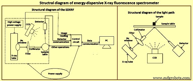
图1 EDXRF光谱仪结构示意图
电磁辐射
电磁辐射是一种能量形式,可以在空间中传播,并且可以与原子和分子相互作用以改变它们的能量状态。这两种特性对光谱学都很重要。电磁辐射表现出的行为需要两种理论来解释。波动理论描述了电磁辐射的行为,例如折射、反射、衍射和散射。辐射被定义为由两个正交波组成的能量形式,每个波具有相同的频率和波长。一个是振荡电场,一个是振荡磁场,因此产生了电磁辐射一词。
在真空中,波在空间中的传播速度是光速(c =3 × 10 的 10 cm/s 次方)。这导致了一个重要的基本关系,由方程 w.v =c 表示。该表达式表明电磁辐射的波长 (w) 与其频率 (v) 的乘积等于其速度。电磁辐射的波长在多个数量级上变化。例如,正常 AM 广播波段中的无线电波具有数百米的波长,紫外线波长在 10 纳米到 100 纳米(纳米)的范围内。相比之下,可用于光谱学的 X 射线范围为 0.01 nm 至 10 nm(图 2)。
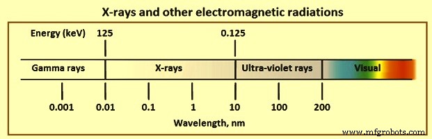
图 2 X 射线和其他电磁辐射
对于波长色散光谱仪,使用波长单位通常更方便,但对于能量色散 X 射线光谱仪 (EDS),能量描述更方便。但是,相互转换很简单。
几种常用的 X 射线特性描述非常重要。电磁辐射强度的正确含义是单位时间单位面积的能量;但是,检测器每单位时间的计数数经常用作强度。因为面积是所用探测器的有效面积,而时间是一个可调参数,所以使用计数是对 X 射线强度的实际描述。术语硬 X 射线或软 X 射线经常用于分别区分短(0.01 nm 至 0.1 nm)和长(0.1 nm 至 1 nm)波长的 X 射线。 X射线属于电磁波谱的高能区。
X 射线发射
X射线是由原子电子轨道的扰动产生的。这可以通过多种方式完成,最常见的是用高能电子、X 射线或加速带电粒子轰击目标元素。前两个经常直接或间接地用于 X 射线光谱分析。电子轰击导致连续的 X 射线能量以及目标元素的辐射特性。在 X 射线光谱学中会遇到这两种类型的辐射。
连续体 – 发射的 X 射线具有相对于能量的平滑、连续的强度函数,称为连续辐射或轫致辐射。可以通过多种方式生成 X 射线连续谱。然而,最有用的是用于轰击 X 射线管中的目标的电子束。连续谱是高能电子撞击目标逐渐减速的结果,这是各种能量轨道电子的分布。当撞击的电子与束缚的轨道电子相互作用时,它们的一些动能转化为辐射。转化的量取决于所涉及的电子的结合能。因此,关于每次交互转换多少能量存在某种统计概率。
撞击电子与目标元素的轨道电子相互作用的概率随着元素的原子序数增加而增加,因此,连续谱发射的强度随着目标元素的原子序数增加而增加。此外,相互作用的概率随着电子束中每单位时间的电子数量或通量而增加。因此,连续谱的强度随着电子束电流的增加而增加,以毫安表示。此外,撞击电子与目标元素的紧密束缚电子相互作用的能力随着轰击电子的动能而增加。由于电子束中电子的动能随着加速电势的增加而增加,连续谱的积分强度随着电子加速电势的增加而增加,以千伏表示。最后,表现为 X 射线光子的最大能量等于撞击电子的动能,而这又与加速势有关。连续体中最大强度的能量位于最大发射能量的三分之二左右。此外,目标材料内的 X 射线吸收或 X 射线管和检测器中用于窗口的材料的吸收。因此,强度分布可能会发生一些变化,尤其是在低 X 射线能量下。
特征发射 – 撞击目标的大部分电子与目标元素的轨道电子以非特异性相互作用的形式发生相互作用,导致内部轨道电子的扰动很少或没有扰动。然而,一些相互作用会导致电子从这些轨道中射出。由此产生的空位或空穴代表高能不稳定状态。如果轨道空位位于最内层的壳层中,则来自外壳层的电子会级联填充它们,这会导致能量较低且状态更稳定。该过程释放的能量可能表现为 X 射线。可能发生的每个跃迁都导致发射具有目标元素特征的尖锐 X 射线线和所涉及的跃迁。这些特征辐射线与连续谱一起发射。
X 射线吸收
撞击样品的 X 射线与样品元素发生两种重要的相互作用:吸收和散射。辐射的吸收可以通过在 X 射线光谱中的样品激发中相当大的特定相互作用或通过影响从样品发射的 X 射线强度的更一般的相互作用来发生。 X射线的散射导致观测光谱中的背景强度。
质量吸收 – 当 X 射线束穿过材料时,光子(电磁场)会以非特定方式与目标元素轨道中的电子相互作用,从而降低 X 射线束的强度。相互作用可导致电子的光电喷射或 X 射线束的散射。在任何一种情况下,总的结果经常被描述为强度随吸收材料的路径长度呈指数下降。质量吸收系数是给定元素在特定 x 辐射能量下的特征。其值随X射线的波长和目标元素的原子序数而变化。
光电效应是导致 X 射线穿过物质时吸收的最重要的过程。光电效应是电子从 X 射线靶中元素的轨道中射出。这个过程通常是 X 射线吸收的主要贡献者,并且是样品中元素发射的 X 射线光谱的激发模式。主要由于光电过程,质量吸收系数随着入射 X 辐射能量的增加而稳步降低。给定元素的吸收与能量曲线具有明显的不连续性。这些是光电过程特别有效的特征能量的结果。
分散 – 当 X 射线光子撞击原子集合时,光子可以与目标元素的电子相互作用,从而导致 X 射线光子的散射,如图 3 所示。来自样品的 X 射线散射为在 X 射线光谱中获得的光谱中背景信号的主要来源。 X 射线的散射主要是由元素的外部弱电子引起的。如果碰撞是弹性的,则发生散射而不会损失能量,称为瑞利散射。如果没有弹性,X 射线光子会失去能量以引起电子的喷射,并且散射是不相干的。 X 射线光子的路径发生偏转,光子有能量损失或更长的波长。这是康普顿散射。
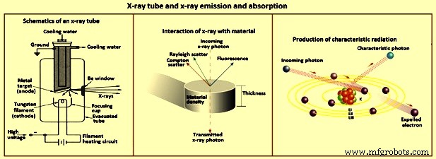
图3 X射线管和X射线发射和吸收
散射以两种方式影响 X 射线光谱。首先,由于电子数量更多,散射辐射的总量随着原子序数的增加而增加。然而,具有低原子序数矩阵的样品显示出较大的观察散射,因为样品的自吸收减少。其次,“康普顿与瑞利”散射强度之比随着样品基质原子序数的降低而增加。与康普顿散射相关的能量损失导致辐射波长发生可预测的变化。
元素和 X 射线之间的关系
元素与X射线的不同关系如图4所示。
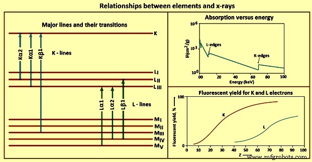
图 4 元素与 X 射线的关系
吸收 – X 射线光子可以与被吸收或散射的元素的轨道电子相互作用。吸收与元素原子序数的关系对于选择X射线光谱的最佳操作条件具有重要意义。
对于给定元素或物质,在给定 X 射线能量和在每个 X 射线能量下,每种元素或物质的质量吸收系数不同。由于与轨道电子相互作用的概率较高,质量吸收系数随着目标材料元素的原子序数增加而增加。在给定的原子序数下,质量吸收系数随着 X 射线辐射的波长而减小。这些是从原子的不同轨道光电射出电子所需的特定能量的结果,是元素的特征。
吸收边缘是质量吸收与入射 X 辐射的波长或能量的关系图中的不连续点或临界点。吸收边缘能量是从元素的轨道光发射电子的确切量。主量子数越低,从该壳层射出电子所需的能量就越高。可以发射 L 个电子的 X 射线的波长比从 K 壳层发射一个电子所需的波长更长(能量更少)。也就是说,对于给定元素,K吸收边能量大于L吸收边能量。
排放 – 光电效应是一种 X 射线吸收机制,通过该机制在原子的电子轨道中产生不稳定状态。一旦形成内部轨道中的空位,就会通过发射激发元素的 X 射线特性而弛豫到稳定的基态。 1s 的能量 电子被价电子的状态屏蔽,使得吸收边能量和发射的X射线的能量基本上与原子的氧化态和键合无关。
K 行 – 一旦光电效应在 K 壳层中产生空位,激发态就会通过用来自外轨道的电子填充空位来放松。由于称为选择规则的量子力学规则,只允许某些转换。遵循选择规则的跃迁被称为允许(图表)线,那些不被称为禁止的跃迁,而那些导致原子在发射时在内轨道中具有两个或更多空位的跃迁被称为卫星(非图表) ) 行。 K 线的数量,以及观察到的元素的确切线数,部分取决于填充轨道的数量。
L 线 – 由于大多数 WDXRF X 射线光谱仪的实际能量范围为 0 keV 到 100 keV,而 EDXRF 光谱仪的实际能量范围为 0 keV 到 40 keV,因此要考虑使用 K 线以外的发射线。对于给定的元素,L 线被激发的 X 射线能量低于 K 线。 L线的使用对于原子序数高于45左右的元素特别有价值。
M 行 -M 线在常规 X 射线光谱中的应用有限。对于原子序数低于 57 左右的元素,没有观察到这些线,当观察到时,跃迁能很低。这些线的唯一实际用途是钍、镤和铀等元素。它们只在这些情况下使用,以避免干扰样品中其他元素的 L 行。
荧光产率 – 电子通过光电过程从原子轨道射出,有两种可能的结果,即 X 射线光子发射或二次(俄歇)电子射出。每个激发的原子都会发生这些事件之一,但不会同时发生。因此,二次电子的产生与样品中激发原子的 X 射线光子发射竞争。发射 X 射线的受激原子的比例称为荧光产额。该值是所考虑的元素和 X 射线线的属性。低原子序数元素也具有低荧光产率。再加上低能X射线具有较高的质量吸收系数,X射线光谱法对低原子序数元素的检测和测定具有挑战性。
元素间效果 – 对于 X 射线光谱中的跃迁,元素的给定系列(K、L、M)的发射线没有能量等于或大于该系列的吸收边。一个重要的结果是,从一个元素发射的 X 射线不能从该元素的其他原子的同一轨道光发射电子。但是,由元素混合物组成的样本可以显示通常称为元素间效应的相互作用。样品中元素的这种相互作用经常需要特殊的数据分析。
WDXRF 光谱仪
1950 年代商业引入的 X 射线光谱仪被称为波长色散仪,它表示从样品发射的辐射使用索勒准直仪进行准直,然后撞击分析晶体。根据布拉格定律并取决于 X 射线的波长或能量,晶体将辐射衍射到不同程度。这种辐射的角度色散允许顺序或同时检测样品中元素发出的 X 射线。
同步仪器通常包含多组分析晶体和检测器;一个针对样品中的每种所需分析物进行调整。虽然价格昂贵,但这些仪器对于预选元素的常规测定非常有效,但除了安装时选择的元素外,不容易转换为测定元素。
更常见的是包含称为测角仪的机械系统的顺序仪器,该系统可以改变样品、分析晶体和检测器之间的角度。这样,可以通过测角仪的移动来选择所需的 X 射线波长。序列 WDXRF 光谱仪可以由计算机控制,用于自动测定许多元素。自动 WDXRF 光谱仪的定量应用是有效的,因为可以对仪器进行编程,使其转到正确的角度进行所需的测定。然而,定性应用的效率较低,因为要对光谱进行缓慢扫描。
X 射线管 – 各种能源可用于在产生 X 射线发射的元素原子中产生激发电子态。其中包括电子束、带电粒子束和 X 射线。电子束以扫描电子显微镜 (SEM) 和电子微探针分析等技术直接照射到样品上。然而,使用电子束需要高真空以避免电子的能量损失。 X 射线光谱法最好用作多功能分析工具,而不是专用工具。许多样品不适合高真空或非导体,在电子束下会导致充电问题。因此,这种能源对于 X 射线光谱仪来说是不实用的。
发射 X 射线的放射性同位素是激发原子发射 X 射线的另一种可能性。然而,可以在实验室安全处理的同位素源的 X 射线通量对于实际应用来说太弱了。由于这些源通常只发射几条窄的 X 射线线,因此需要几条才能有效地激发许多元素。 X射线光谱仪最实用的能源是X射线管(图3)。
WDXRF 光谱仪需要高效的大功率激发才能表现良好。因此,X射线管的稳定性和可靠性很重要。所有组件都处于高真空状态。灯丝由 6 V 至 14 V 的灯丝电压加热。加热的灯丝热发射电子。在灯丝和目标阳极之间流动的电子通量将受到高度调节和控制。这种电子流是电流,通常以毫安为单位测量。管电流通常称为mA。
在灯丝(阴极)和目标阳极之间施加几千伏的电势,用作电子的加速电势。该电压通常以千伏为单位。阳极通常为铜,靶表面镀有诸如铑、银、铬、钼或钨等元素的高纯度沉积物。用于 WDXRF 光谱测定的 X 射线管的工作功率为 2 kW 至 3 kW。这种功率的大部分以热量的形式消散,因此需要对 X 射线管进行水冷。这些 X 射线管的电源和相关电子设备很大。电子以与施加的管电势相当的最大动能撞击目标。如果电子的动能超过对应于从目标材料的原子中射出内轨道电子的吸收边缘能量,则该管发射目标元素特征的X射线线。束中的电子与目标元素的电子的相互作用也导致连续谱的发射。连续谱的面积和最大强度的波长取决于电位、电流和阳极成分。
分析晶体 – X 射线管发出的 X 射线直接照射到样品上。在大多数 X 射线光谱仪中,样品被放置在 X 射线管上方,即所谓的倒置光学系统。这有助于使用底部表面而不是顶部来定位液体表面。从样品发射的 X 射线被准直并撞击在分析晶体的表面上,从而分散辐射。来自样品的多色 X 射线平行光束从晶体中的不同晶格平面衍射。如果辐射通过衍射从不同晶格平面传播的额外距离等于波长的整数倍,则会发生增强。如果不是这种情况,则会发生相消干涉。布拉格定律允许计算为分析晶体选择波长的角度。
探测器 – WDXRF 光谱仪中的检测器和相关电子设备检测从分析晶体衍射的 X 射线,并拒绝不需要的信号,例如分析晶体的高阶或低阶衍射或检测器噪声。两个检测器通常串联放置。第一种是充气或流动气体比例检测器。这些探测器由与外壳绝缘的电线组成。外壳前部和后部的薄聚合物窗口允许 X 射线进入和可能退出。在电线和外壳之间施加了几百伏的偏置电位。
虽然可以使用多种气体,但典型的气体是 P-10,即 90% 氩气 (Ar) 和 10% 甲烷的混合物。当 X 射线进入检测器时,氩气被电离以产生许多 Ar+-e- 对。阳极线收集电子,外壳阴极壁上的电子中和 Ar+ 离子。结果是进入探测器的每个 X 射线光子的电流脉冲。 P-10 填充比例检测器对于检测能量小于约 8 keV(波长高于约 0.15 nm)的 X 射线光子最有效。更高能的X射线倾向于通过比例探测器。
通常位于比例计数器后面的第二个检测器通常是闪烁检测器。该探测器由掺铊的碘化钠晶体 [NaI(Tl)] 组成,当被 X 射线光子撞击时,它会发出一束蓝色 (410 nm) 光。晶体安装在检测光脉冲的光电倍增管上。产生的光子数量与入射 X 射线光子的能量成正比。在电子处理之后,闪烁脉冲串被转换为与 X 射线光子能量成比例的电压脉冲。这两个检测器可以独立或同时操作。在同时操作中,检测器的工作电位和输出增益将被调整,以便给定能量的 X 射线光子从两个检测器产生相同的脉冲高度电压。两种探测器类型都需要大约 1 微秒才能在脉冲之间恢复。当入射光子速率大于约 30,000/s 时,一些计数可能会丢失。来自探测器的 X 射线脉冲的脉冲高度区分拒绝从分析晶体衍射的更高或更低阶的 X 射线。
操作基础 – 当考虑样品并选择分析元素时,第一个决定是选择发射线。在没有特定干扰的情况下,通常使用最有可能的能量线。对于原子序数小于 75 左右的元素,这通常是 K 线,因为许多 WDXRF 光谱仪可以在 X 射线管的 100 kV 电位下工作。在可能的情况下,选择 X 射线管,其发射能量正好高于用于分析物元素的吸收边缘的能量线。当这种管子不可用时,激发是通过使用一个可用的X射线管的连续谱来完成的。
X 射线管的电位应设置为吸收边缘能量的 1.5 倍左右或更高。检测器将根据要使用的波长区域进行选择。比例计数器用于长于约 0.6 nm 的 X 射线,闪烁检测器用于波长短于约 0.2 nm 的 X 射线,两者都用于 0.2 nm 至 0.6 nm 的重叠区域。选择允许检测所需波长的分析晶体。大部分参数选择是通过计算机控制进行的。
能量色散 X 射线光谱仪
在 WDXRF X 射线光谱仪中使用测角仪是基于将样品中各种元素发射的 X 射线分解为成分的要求。在许多类型的光谱学中都使用色散装置来完成这项任务。如果可以实现足够的分辨率,则需要没有机械组件的仪器。 1960年代中期锂漂移硅探测器的发展及其在X射线探测中的应用催生了光谱分析领域,即EDXRF光谱法。
WDXRF 光谱仪中使用的 X 射线管的额定功率为 2 kW 到 3 kW,并且是水冷的。 EDXRF 光谱仪中使用的那些以低得多的功率运行,并且通常是空气冷却的。典型的管子范围从 9 W 到 100 W。有不同的阳极材料可供选择,每个 X 射线光谱仪制造商都提供特殊的 X 射线管功能。然而,经过多次试管设计试验,大多数仍然采用传统的“侧窗”设计,尽管它比 WDXRF 光谱仪中使用的要小得多。电子管和相关电源设计的一个主要因素是电子管的稳定性和电压。
直接 X 射线管激发的替代方法是使用次要目标激发。在这种模式下,X 射线管用于照射次要目标,其特征 X 射线荧光又用于激发样品的 X 射线发射。由于使用次要靶时效率损失很大,因此需要比直接激发更高瓦数的 X 射线管。
次要目标激发有时具有显着优势。例如,为了确定铁样品中钒和铬的低浓度水平,可以用铁次要目标激发这些元素,而无需激发样品中的铁。对于直接管激发,这很困难。需要几个次要目标来涵盖广泛的要素。支持使用次要目标激发作为激发的单色辐射源。这一优势的意义在于,许多用于直接从基本 X 射线方程计算强度的基本参数计算机程序都需要单色激发辐射。
在实践中,次要目标激发只接近理想的单色辐射。与二级目标技术相比,采用适当初级过滤器的直接管激发性能良好。因此,直接 X 射线管激发对于能量色散光谱 (EDS) 的大量应用来说仍然是最实用的。 EDS 技术的主要优势在于其同时进行多元素分析的能力。尽管会出现需要选择性激发的特殊情况,但这通常可以通过智能使用适当的 X 射线管和滤光片来实现。任何限制同时多元素能力的基本设计特征都会削弱 EDXRF 光谱仪的优势。
Since direct x-ray tube excitation is the most common method used in EDS, there are factors which govern the selection of an x-ray tube. In wavelength-dispersive techniques, several x-ray tubes are normally available for the spectrometer. These can be changed for different applications. This is not normally the case with EDS-systems, since many WDXRF spectrometer has few if any choices of primary filters. In wavelength-dispersive techniques, it is customary to attempt to excite the desired element by the characteristic emission lines of the tube anode material, but the continuum is used more efficiently in EDXRF spectrometers. The use of EDXRF spectrometers has been enhanced by computer control of tube current and voltage and selection of the primary filter. Selection and efficient use of a single x-ray tube is important in the configuration of an EDXRF system.
Characteristic lines emitted by an x-ray tube have much larger intensity at their maxima than the continuous radiation emitted. These lines are to be used for excitation whenever possible. In addition, use of a primary filter between the x-ray tube and the sample can effectively approximate monochromatic radiation impinging on the sample from these characteristic lines. EDXRF spectrometers normally offer various x-ray tube anode materials. For selecting the x-ray tube anode material, the applications most likely to be encountered are to be considered.
The principal concern is to select an anode which has characteristic lines close to, but always higher, in energy than the absorption-edge energies to be encountered. None of the characteristic lines are to create spectral interference with elements to be determined. This includes consideration of such details as the Compton scatter peak for the characteristic lines. In addition, it is difficult to perform determinations of the element of the anode material. This is especially true with samples having low concentrations of that element.
Rhodium is a favourable tube anode material for general-purpose use. The characteristic lines of this element are efficient for the excitation of elements with absorption edges to around 15 keV. The excitation efficiency for the K lines of the transition elements is low. However, the continuum can be used efficiently in this region. Rhodium also has characteristic L lines at around 2.7 keV to 3.0 keV. These are efficient for the excitation of the K lines of low atomic number elements, such as aluminum, silicon, phosphorus, and sulphur. However, in these cases, a silver anode is preferable because of the Compton scatter radiation from the rhodium lines. The characteristic lines and the continuum from the x-ray tube can be used for excitation.
Although the elements of many samples can be excited effectively using a combination of the characteristic x-ray lines from the tube anode element and the continuum, more monochromatic radiation is sometimes desired. One such situation involves enhancing the use of fundamental-parameter computations which permit quantitative determination of elements without the need for several concentration standards. A more frequent situation is the need to reduce the background in the spectrum energy range to be used in the analysis. Use of primary filters placed between the x-ray tube and the sample can be effective in these cases and are normally incorporated under computer control in commercial spectrometers.
The object is to filter the primary radiation from the x-ray tube and selectively pass the characteristic lines of the anode element. This is accomplished using a filter made of the same element as the tube anode. Since x-rays of a given line (K, L, and so on) of an element are lower in energy than the absorption edge for that element, the photoelectric component of the mass absorption coefficient is small. Such a filter does not efficiently absorb the characteristic line emitted by the x-ray tube. The higher energy x-rays from the continuum are efficient for the photoelectric process in the filter and are highly attenuated by absorption. X-rays of lower energy than the filter material absorption edge are absorbed more efficiently as the energy decreases.
The result is x-radiation striking the sample with an intensity which is largely determined by the characteristic lines of the tube anode and that approximates monochromatic radiation. Increasing the thickness of the filter decreases the total intensity, with further gain in the monochromatic approximation.
Detectors – The selective determination of elements in a mixture using x-ray spectrometry depends upon resolving into separate components the spectral lines emitted by the different elements. This process needs an energy-sorting or wavelength-dispersing device. For the WDXRF spectrometer, this is accomplished by the analyzing crystal, which needs mechanical movement to select each desired wavelength according to Bragg’s law. Optionally, several fixed-crystal channels can be used for simultaneous measurement. In contrast, EDS is based on the ability of the detector to create signals proportional to the x-ray photon energy. Hence, mechanical devices, such as analyzing crystals, are not needed.
Several types of detectors have been used, including silicon, germanium, and mercuric iodide. The solid-state, lithium-drifted silicon detector [Si(Li)] was developed and applied to x-ray detection in the 1960s. By the early 1970s, this detector was firmly established in the field of x-ray spectrometry and was applied as an x-ray detection system for SEM and x-ray spectrometry. The Si(Li) detector provides excellent resolution. It can be considered as a layered structure. Under reversed bias of around 600 V, the active region acts as an insulator with an electric-field gradient throughout its volume.
When an x-ray photon enters the active region of the detector, photo ionization occurs with an electron-hole pair created for each 3.8 eV of photon energy. Ideally, the detector is to completely collect the charge created by each photon entry and result in a response for only that energy. Some background counts appear because of energy loss in the detector. Although these are kept to a minimum by engineering, incomplete charge collection in the detector contributes to background counts. From 1 keV to 20 keV, an important region in x-ray spectrometry, silicon detectors are efficient for conversion of x-ray photon energy into charge.
Analyzer systems – The x-ray spectrum of the sample is obtained by processing the energy distribution of x-ray photons which enter the detector. One x-ray photon entering the detector causes photo-ionization and produces a charge proportional to the photon energy. Several electrical sequences are to take place before this charge can be converted to a data point in the spectrum. A detailed knowledge of the electronics is not necessary, although an understanding of their functions is important. Upon entering the Si(Li) detector, an x-ray photon is converted into an electrical charge which is coupled to a field effect transistor (FET). The FET and the electronics comprising the preamplifier produce an output proportional to the energy of the x-ray photon. Using a pulsed optical preamplifier, this output is in the form of a step signal. Since photons vary in energy and number per unit time, the output signal, due to successive photons being emitted by a multi-element sample, resembles a staircase with various step heights and time spacing. When the output reaches a determined level, the detector and the FET circuitry reset to their starting level, and the process is repeated.
The preamplifier output is coupled to a pulse processor which amplifies and shapes the signal into a form acceptable for conversion to a digital form by an analog-to-digital converter (ADC). Amplification is necessary to match the analog signal to the full-scale range of the ADC. This process involves the energy calibration of the spectrometer. Drift in the gain and/or offset (zero) of the amplification results in errors in the energy assigned to the x-ray photons producing the signal. Hence, these calibrations are to be as stable as possible, and calibration is to be routinely checked.
The energy calibration is important for qualitative identification of the elements and for precise quantitative results when using spectrum-fitting programs. The amplifier provides gain and zero controls for calibrations. Normal operation in x-ray spectrometry is to set the time on the system clock to be used to acquire the spectrum. The processing of the pulses is not instantaneous. At high count rates, the time needed can become significant. When a pulse is detected and processing initiated, the clock is ‘stopped’ until the system is ready to process a new photon. The length of time the clock is off is called dead time; the time the clock is on is called live time. Their total is real time. The system monitors live time. If the spectrometer is operated with a 50 % dead time, the real time is twice the live time.
Processing of the pulse created by a photon is to be complete before another pulse occurs. A pulse pile-up rejector circuit blocks a pulse if it is received too soon. Once activated, the pulse pile-up rejector prevents the new signal from being processed if a second x-ray enters the detector before a prior pulse is fully processed. If analysis of the prior pulse had not yet been complete, it is also to be blocked from further processing. If this blockage is not performed, pulse pile-up occurs, resulting in an artifact which appears at energies equal to the sum of the photon energy of the first and second photons to enter the detector. These are frequently called sum peaks.
Despite pulse pile-up rejection circuitry, sum peaks are observed for intense peaks in the spectrum. This is the result of two photons entering the detector simultaneously or within a time difference faster than the fast discriminator can act. Sum peaks can be observed at twice the energy of an intense peak and / or at the sum of the energies of two intense peaks in the spectrum. Sum peaks decrease rapidly in intensity with count rate. The importance of electronic pulse-processing components to system performance is easily overlooked in EDS. However, stability, linearity, and proper calibration of these components are important for the use of the spectrometer.
EDXRF spectrometers require a dedicated computer system for data acquisition. Early spectrometers were heavy, unwieldy units which used hard-wired multichannel analyzers which could acquire data, but could do little to process it. Current spectrometer and data systems based on microprocessor technology are available as table-top units.
Fundamentals of operation – The simultaneous multi-element capability of EDS complicates the selection of optimum conditions because of the factors to be considered for each element. The compromises in spectroscopy are to be made, but the initial selection of instrument operating conditions can follow a logical sequence of decisions.
Qualitative analysis needs similar procedures, normally with less stringent requirements. Once a sample is received for analysis and the elements to be determined by x-ray spectrometry are identified, the next decision is to ascertain which x-ray lines are to be used for the determinations. As a general rule, K lines are used upto a K absorption-edge energy a few keV below the characteristic line of the x-ray tube anode element. The continuum can be used for excitation if the voltage to the x-ray tube is set sufficiently high to place the continuum maximum at energy higher than the absorption edge and if a back-ground filter is used. In these cases, K absorption-edge energies can be used upto around 66 % of the maximum operating kV of the x-ray tube. However, the observed peaks lie on a continuum background and reduce the signal-to-noise ratio.
For a 50-kV x-ray tube, absorption edges as high as 30 keV can be used if the element is present in sufficient concentration. For a 30-kV rhodium or silver tube, one is restricted essentially to excitation by the characteristic tube lines. This is of no great concern unless there is a special interest in the elements between atomic numbers 41 and 50 (niobium to tin). Elements above atomic number 50 (40 for a 30-kV system) are normally to be determined using the L lines of their x-ray spectra.
To excite all L lines, the incident x-ray photon energy is to exceed the LI absorption edge. For practical use, the energy of the L lines is to be higher than around l keV. For the L line spectra, this needs atomic numbers higher than 30. At such low x-ray energies, absorption of the x-rays and low fluorescent yield in the L emission in this region needs high concentration of the element to be determined and excellent sample preparation. Overlap of the K lines of the low atomic number elements in this region also causes difficulty. For example, the K lines of phosphorus overlap with the L lines of zirconium and the M lines of iridium at around 2 keV. These problems are to be considered, but are to a large degree solved by careful use of processing software.
Once the x-ray spectral lines are selected for determination of the elements, the next step is to decide whether all analyte elements in the sample can be determined with one instrumental setting. Although the multi-element capability of EDS is useful, all elements in every sample cannot be determined with a single set of instrument parameters. Some applications need more than one condition, such as a mixture of low atomic number elements and transition elements. The transition elements are best determined by excitation using the K lines of rhodium or silver and the low atomic number elements with the L lines or a properly adjusted continuum using a background filter. Computer control of instrument parameters facilitates changing the conditions. Whether automatic or manual control is used, all samples are to be analyzed under one set of conditions, then analyzed again using the alternate set. This is preferred over changing conditions between samples.
X-ray tube operating voltage affects the efficiency of excitation of each element in the spectrum and the integrated x-ray photon flux from the tube. The tube current affects the flux only. Hence, once the operating kV has been set, the tube current typically is adjusted until the system is processing counts efficiently. System dead time is to be maintained below, but near, 50 %. The voltage and current settings for the x-ray tube have a sensitive effect on the rate of information acquisition and count distribution among the respective spectral peaks for a given type of sample.
Selection of primary tube filter thickness is important. If the filter is changed, the tube current, and sometimes the voltage, frequently needs resetting since the filter alters the intensity distribution of the x-rays striking the sample. When characteristic tube lines are used for excitation, the filter is normally made from the tube anode element. The intensity of the transmitted x-rays decrease exponentially with increasing filter thickness. It is common to have two or three primary filters made from the tube anode element in the filter holder. The selection is to reflect optimum count rate corresponding with reasonable current and voltage settings. Thicker filters attenuate lower energy radiation more effectively and reduce the excitation efficiency for the element with low absorption coefficients.
The remaining decision is the choice of atmosphere in the sample chamber. If x-rays below around 5 keV are to be implemented, use of a vacuum can be advantageous. Intensity can increase sufficiently to reduce significantly the counting time needed to achieve an adequate number of counts. If the concentration of elements yielding these x-rays is sufficiently high, the vacuum may not be needed. Because of the extra precautions needed in sample criteria and handling, a vacuum path is not to be used unless significant benefit is realized. Similar reasoning applies to the helium atmosphere.
These guidelines are useful for initial selection of operating conditions. The instrumental parameters are interactive, and a change in one parameter needs adjustment of another. For example, selection of a thicker primary filter or a decrease in the tube voltage needs an increase in the tube current.
Sample preparation
The care taken to determine the best method of sample preparation for a given material and careful adherence to that method frequently determine the quality of results obtained. Sample preparation is the single most important step in an analysis, yet it is frequently given the least attention. In most cases, the stability and overall reproducibility of x-ray instrumentation are the least significant factor affecting the precision of analytical measurements. Frequently, the precision of analytical results expected from x-ray spectrometric determinations is expressed in terms of the theoretical statistics of measurement of x-ray intensities.
When replicate samples are prepared and actual standard deviations measured, deviations are found to be larger than those predicted by counting statistics. If precision is poor, any one analytical result can also be poor, since it can differ substantially from the ‘true’ value. The variety of sample types which can be analyzed using x-ray spectrometry necessitates different sample preparation techniques.
Samples are frequently classified as infinitely thick or infinitely thin based on measurement of the attenuation of x-rays. Samples are considered to be infinitely thick if further increase in the thickness yields no increase in observed x-ray intensity. The critical value for infinite thickness depends on the energy of the emitted x-radiation and the mass absorption coefficient of the sample matrix for those x-rays. For pure iron, the critical thickness is around 40 m for iron x-rays.
Although infinitely thin samples afford several advantages, it is rarely feasible to prepare them from routine samples. Many samples fall between these two cases and need extreme care in preparation. In addition to preparation of the sample, precise positioning of the sample in the spectrometer is critical for quantitative determinations.
Solid samples – These are defined as single bulk materials, as opposed to powders, filings, or turnings. Solid samples can frequently be machined to the shape and dimensions of the sample holder. The processing is not to contaminate the sample surface to be used for analysis. In other cases, small parts and pieces are to be analyzed as received. The reproducible positioning of these samples in the spectrometer is critical. It is frequently useful to fashion a wax mould of the part which fits into the sample holder. Using the mould as a positioning aid, other identical samples can be reproducibly placed in the spectrometer.
Samples taken from unfinished bulk material frequently needs surface preparation prior to quantitative analysis. Surface finishing can be done using a polishing wheel, steel wool, or belt grinder, with subsequent polishing using increasingly fine abrasives. Surface roughness less than 100 micrometers is normally sufficient for x-ray energies above around 5 keV, but surface roughness of less than 20 micrometers to 40 micrometers is needed for energies down to around 2 keV. Several precautions are necessary. Alloys of soft metals can smear on the surface as the sample is polished, resulting in a surface coating of the soft metal which yields high x-ray intensities for that element and subsequently high analytical results.
Polishing grooves on the surface of the sample can seriously affect the measured intensity of low-energy x-rays. This can be examined by repetitive measurement of the intensity of a sample after 45 degrees or 90 degrees rotation. Use of a sample spinner reduces this effect. If a sample spinner is not available, the sample is to be placed in the spectrometer such that the incident x-radiation is parallel to the polishing direction.
Powders and briquettes – Powder samples can be received as powders or prepared from pulverized bulk material too inhomogeneous for direct analysis. Typical bulk samples pulverized before analysis are ores, and refractory materials. Powders can be analyzed using the spectrometer, pressed into pellets or briquettes, or fused with a flux, such as lithium tetra borate. The fused product can be reground and pressed or cast as a disk. For precise quantitative determinations, loose powders are rarely acceptable, especially when low-energy x-rays are used. Pressed briquettes are more reliable. However, experience indicates that the best compromise is reground and pressed fusion products. This technique eliminates several problems associated with particle-size effects.
Particle-size effects result from the absorption of the incident and emitted x-rays within an individual particle. If the mass absorption coefficient of the sample matrix is high for the x-radiation used, particles even a few microns in diameter can considerably affect attenuation of the radiation within each particle. If the sample consists of particles of various sizes, or the particle size varies between samples, the resulting x-ray intensities can be difficult to interpret. This problem is compounded by the tendency of a material composed of a mixture of particle sizes to segregate when packed.
Determination of elements using low-energy x-radiation can lead to errors from particle-size effects of as much as 50 %. If the needed speed of analysis prohibits use of fusion techniques, direct determination from packed powders can be considered. The sample is to be ground, if possible, to a particle size below the critical value. The grinding time needed frequently can be ascertained by measuring the intensity from a reference sample at increasing grinding times until no further increase is observed. The lowest energy x-ray to be used in analysis is to be selected for this test.
Briquettes or pressed powders yield better precision than packed powder samples and are relatively simple and economical to prepare. In several cases, only a hydraulic press and a suitable die are needed. In the simplest case, the die diameter is to be the same as the sample holder so that the pressed briquettes fit directly into the holder. The amount of pressure needed to press a briquette which yields maximum intensity depends on the sample matrix, the energy of the x-ray to be used, and the initial particle size of the sample. Hence, prior grinding of the sample to a particle size which is less than 100 micrometers is advisable.
A series of briquettes are to be prepared from a homogeneous powder using increasing pressure. The measured intensity of the x-ray lines to be used in the analysis is plotted versus the briquetting pressure. The measured intensity is to approach a fixed value, perhaps asymptotically. Pressures of 138 MPa to 276 MPa may be needed. For materials which do not cohere to form stable briquettes, a binding agent is needed. Acceptable binding agents include powdered cellulose, detergent powders, starch, stearic acid, boric acid, lithium carbonate, polyvinyl alcohol, and commercial binders.
Briquettes which are not mechanically stable can be improved by pressing them into backing of pre-pressed binder, such as boric acid, or by the use of a die which presses a cup from a binding agent. The sample powder can then be pressed into a briquette supported by the cup. Improved results are frequently achieved if around 0.1 mm to 0.5 mm is removed from the surface of the briquette prior to the measurement.
Fusion of materials – Fusion of materials with a flux can be performed for several reasons. Some refractory materials cannot be dissolved, ground into fine powders, or converted into a suitable homogeneous form for x-ray spectrometric analysis. Other samples can have compositions which lead to severe inter-element effects, and dilution in the flux reduces these. The fused product, cast into a glass button, provides a stable, homogeneous sample well suited for x-ray measurements. The disadvantages of fusion techniques are the time and material costs involved as well as the dilution of the elements which can result in a reduction in x-ray intensity. However, when other methods of sample preparation fail, fusion frequently provides the needed results.
Low-temperature fusions can be carried out using potassium pyro-sulphate. More common are the glass-forming fusions with lithium borate, lithium tetra-borate, or sodium tetra-borate. Flux-to-sample ratios range from 1:1 to 10:1. The lithium fluxes have lower mass absorption coefficients and hence less effect on the intensity of the low-energy x-rays. An immense variety of flux-additive recipes are reported for various sample types. Lithium carbonate can be added to render acidic samples more soluble in the flux. Lithium fluoride has the same effect on basic samples. Lithium carbonate also reduces the fusion temperature. Oxidants, such as sodium nitrate and potassium chlorate, can be added to sulphides and other mixtures to prevent loss of these elements.
Filters and ion-exchange resins – Various filters, ion-exchange resin beads, and ion-exchange resin-impregnated filter papers have become important sampling substrates for samples for x-ray spectrometric analysis. Filter materials can be composed of filter paper, membrane filters, glass fiber filters, and so on. Filters are used in a variety of applications. One widely used application is in the collection of aerosol samples from the atmosphere. Loadings of several milligrams of sample on the filter can correspond to sampling several hundred cubic meters of atmosphere. Such sampling can be performed in any environment. Many elements can be determined directly on these filters by x-ray spectrometric analysis. Particulate samples collected in this way present problems, stemming primarily from particle-size effects, which are reduced in part by the need to collect two particle-size regions using dichotomous samplers. With these units, particles are separated into those smaller and those larger than around 2 micrometers in diameter.
The smaller particles tend to represent man-made materials; the larger ones are of natural origin. The smaller particles show fewer particle-size effects, and an x-ray spectrometric determination of even low atomic number elements, such as sulphur, is possible. Glass fiber filters are frequently used for this purpose. Filters can also be used for non-aerosol atmospheric components, such as reactive gases. Filter materials can be impregnated with a reagent reactive to the gas which traps it chemically. Sampling is accomplished by conveying atmospheric gases through a treated filter under carefully controlled conditions. An example is a damp filter treated with ferric ion solution used to trap hydrogen sulphide. The excess iron can be rinsed from the filter, but the precipitated ferrous sulphide remains. The sulphur can be determined directly or indirectly by measuring the iron x-radiation. The key to determining atmospheric components is the development of suitable standards.
Filters can be used to determine solution components in ways parallel to those described for atmospheric components. Particulate materials can be filtered directly from solution. For example, particulate materials in environmental water samples are defined as that which is filtered using a 0.45 micrometer pore diameter membrane filter. Hence, filtration of particles from water can be accomplished using such filters, and direct x-ray spectrometric analysis performed. Application of filter sampling to dissolved elements in water is becoming more common. The principle is similar to the reactive reagent-impregnated filter application to atmospheric gases. In some cases, the filter can be impregnated with ion-exchange resins which trap ions as the solution passes through the filter.
Procedures using ion-exchange resin-impregnated filters are to be carefully checked, since several passes of the solution can be needed, and distribution of the ions across the paper thickness is seldom uniform. However, for solutions, a reaction can be performed prior to filtration. For example, many ions can be precipitated quantitatively from aqueous solution, even at parts per billion concentration levels. The precipitates can be collected using 0.45 micrometers pore diameter membrane filters, which are then mounted between two Mylar sheets retained by ring clips on a standard plastic sample cup. Simultaneous multi-element determinations are then performed using XRF spectrometer.
Detection limits on the filters of as low as a few tenths of a microgram are common. If 100 g of sample solution is used, this corresponds to the detection limits of a few parts per billion in the sample. Standards are easily prepared as aqueous solutions. ‘Standard reference materials’ (SRM) for environmental waters and industrial effluent water are available.
Thin-film samples – Thin-film samples are ideal for x-ray spectrometric analysis. The x-ray intensity of an infinitely thin sample is proportional to the mass of the element on the film, and the spectral intensities are free of inter-element and mass absorption coefficient effects. However, in practice, perfect thin-film samples are rarely encountered. Powder samples of sufficiently small and homogeneous particle size can be distributed on an adhesive surface, such as cellophane tape, or placed between two drum-tight layers of Mylar film mounted on a sample cup.
More important thin-film types are platings and coatings on various substrates. Analysis of these sample types is increasingly important for the electronics industry. Of particular concern are measurements of film thickness and composition. Several techniques can be used, including the substrate intensity attenuation method, the coating intensity method, various intensity ratio methods, and the variable takeoff angle method. The last method is not practical in most commercial spectrometers. To be infinitely thin to most x-rays used in x-ray spectrometric analyses, the samples are to be 10 micrometers to 200 micrometers thick.
Liquids – Liquids can also be analyzed using x-ray spectrometry. The design of x-ray spectrometric instrumentation using inverted optics, in which the sample is above the x-ray source and detector, facilitates the use of liquid samples. This convenient geometry demands caution in the preparation of liquid samples to avoid damaging the source or detector by such accidents as spills and leaking sample cups.
Quantitative standards are easily prepared for liquid samples. However, since solvents are normally composed of low atomic number elements, the Rayleigh and Compton scatter intensity is high, which increases background and leads to high limits of detection. These problems can be minimized by use of suitable primary tube filters, which reduce the scattered x-radiation in the analytically useful region.
Care is to be taken with liquids containing suspended solids. If the suspension settles during the measurement time, the x-ray intensity of the contents of the sediment is enhanced. The x-ray intensity from solution components or homogeneous suspension can decrease as a result of sediment absorption, which leads to erroneous results. This possibility is tested by brief, repetitive measurements, beginning immediately after a sample is prepared. Any observed increase or decrease in intensity with time indicates segregation in the sample. In these cases, an additive which stabilizes the suspension can be used, or the suspended content can be collected on a filter for analysis.
Special sample types – Applications of x-ray spectrometric analysis do not always provide convenient samples which can fit one of the above categories. Non-destructive analyses are occasionally needed on production products which are not 32 mm diameter circles of infinite thickness. Examples include computer disks, machined parts, and long, coated strips or wire. In these cases, a sample compartment which accommodates the samples can frequently be designed. With the development of the mercuric iodide detector, which can provide adequate resolution for many analyses without a liquid nitrogen dewar, special analytical systems for on-line and non-destructive analysis of large samples can become increasingly feasible.
制造工艺