

5 单元 4:偏置镗头
目标
完成本单元后,您应该能够:
- 识别偏置镗头
- 说明如何更正转台的设置。
偏移镗头
偏置镗孔是一种适合铣床主轴的附件,允许大多数钻孔具有更好的光洁度和更大的直径精度。当公差不允许钻头或没有足够大的钻头或铰刀时,偏置镗头用于制造大孔。偏心镗头可用于扩大孔,或在某些情况下调整孔中心线。
安全:
确保所有固定螺钉在操作前都已拧紧。确保偏置镗头在镗孔时有一个间隙可以装入孔中。转动铣刀前拆下内六角扳手。运行前仔细检查磨机速度。
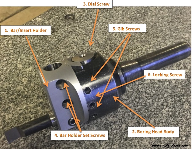
图 1. 偏置镗头
偏移镗头和工具
图 1. 显示偏置镗头。请注意,可以在直角轴上调整镗杆。这一特性使得镗刀可以精确定位以钻孔不同直径的孔。
这种调整比调整镗杆架中的刀具或更换镗杆更方便。偏心镗头的另一个优点是,带刻度的千分尺轴环允许刀具在不使用百分表或其他测量装置的情况下以 (0.001) 的增量精确移动指定的量。
偏移镗头
一个镗头具有三个主要组成部分:
- 无聊的头身
- 杆架/刀片架
- 表盘螺丝
镗头主体具有黑色氧化处理,可防止生锈。杆架或刀片架 (#1) 进行了缎面镀铬处理以提高耐磨性。刻度盘螺钉 (#3) 已经过精密磨削,可在燕尾滑块中准确移动杆架/刀片架。绞线张力已在工厂预设。不应松开两个凸角螺钉 (#5) 进行尺寸调整。这些螺钉仅用于调节压条压力,并用红蜡填充以防止意外调节。锁定螺钉 (#6) 是唯一用于改变钻孔头尺寸的螺钉。
直径调整
调整 Allied Criterion 标准镗头的直径:
1. 松开锁紧螺丝(#6)。
2. 顺时针转动刻度螺丝(#3)增大直径,逆时针转动减小直径。
3. 拧紧锁定螺钉 (#6)。调整标准镗头
程序:
- 设置工作并仔细对齐工作台行程。
2.将铣床主轴的中心与工件上的参考点对齐。
3.用中心钻或定位工具定位孔的位置。
4.钻孔超过½英寸,确保偏置镗头在镗孔时有间隙以适合孔。
5.将钻孔头安装到铣床中。
6.安装镗杆,拧紧定位螺钉,松开锁紧螺钉,将镗杆调整到孔边缘。
7.重新检查工件对齐,以及主轴与参考点的对齐,以确保它没有偏移。如果有明显错误,则需要在处理前重复步骤 6。
8.根据孔尺寸和材料调整铣床速度。
9.在磨机上使用蠕虫饲料。把羽毛笔带到材料上。拉出手柄以接合电源。当达到所需深度时,将手推回以脱离进给,然后关闭 Mill。从孔中取出钻孔头。
10.完成钻孔至所需尺寸。
注意:重复步骤 6-9,直到孔达到所需尺寸。
转台
转台可用于制作圆弧和圆。例如,可使用转台制作虎钳旋转底座中的圆形 T 形槽。转台也可用于分度,其中工件必须在操作之间旋转精确的量。您可以使用转台在铣床上制造齿轮。分度盘使转盘分度更容易。
转台最常见的是“平装”安装,转台围绕垂直轴旋转,与立式铣床的刀具在同一平面内。另一种设置是将转台安装在其末端(或将其“平”安装在 90°角板上),使其绕水平轴旋转。在这种配置中,也可以使用尾座,从而将工件固定在“中心之间”。
工作台安装在辅助工作台上,工件以转台轴线为中心,而转台轴线又以刀具轴线为中心。因此所有三个轴都是同轴的。从这一点开始,辅助工作台可以在 X 或 Y 方向上进行偏移,以将刀具设置为距工件中心所需的距离。这允许对工件进行同心加工操作。将工件偏心放置在距中心一定距离的位置允许切割更复杂的曲线。与立式铣刀上的其他设置一样,铣削操作可以是钻一系列同心且可能等距的孔,也可以是平面或端铣圆形或半圆形形状和轮廓。
可以使用转台:
- 在螺栓上加工扳手平面
- 在圆形法兰上钻等距的孔
- 切一个带有突出柄脚的圆片
- 在无法驱动大型麻花钻 (>0.500″/>13mm) 的小型铣床上通过在圆形刀具路径中铣削来创建大直径孔
- 研磨螺旋线
- 切割复杂曲线(通过适当的设置)
- 以任意角度切割直线
- 切割弧线
- 通过在旋转工作台顶部添加复合工作台,用户可以将旋转中心移动到被切割零件的任何位置。这样就可以在零件的任何位置切割弧线。
- 切割圆形片
设置转台
在铣床上使用转台时,无论是铣削圆弧还是在某些圆形图案中钻孔,都必须做两件事来设置工件。首先,工件必须在转台上居中。其次,转台必须在主轴下方居中。然后可以将铣床移动一段适当的距离,您就可以开始切割了。
您可以先将工作台置于主轴下方,通过指示工作台中心的孔来使工作台居中。然后您可以将工件安装在工作台上并指示工件。这种方法有两个问题。首先,您假设表格中的孔是真实的并且居中。这可能是真的,也可能不是。其次,这种方法存在累积误差的风险,因为您要从两个不同的特征(转台的孔和工件上的某些特征)进行测量。先将工件在转台上对中,再将转台在主轴下方对中。
要将工件放在转台上,请旋转转台并注意指示器指针的偏转。根据需要调整磨盘的位置(X和Y),直到针不再偏斜。
您可以通过将千分表测试指示器放置在主轴的卡盘或夹头中来拨入转台,然后用手旋转,使指示器尖端与转台的孔接触。如果您的机器可以脱离齿轮,这样做会有所帮助,因此主轴可以自由摆动。使用钻夹头显然也比使用夹头更容易,所以你有一些可以轻松转动的东西。使用鞍座和桌面手轮进行调整。
一旦你找到中心(当你旋转主轴时,指示器的读数会相同,最好将两个刻度盘都设置为“0”,而不是标记一些随机位置。确保你也正确设置了间隙. 将表盘设置为正向读数,因此很容易计算任何变化,而且您永远不必记住您选择了哪种方式来设置反向间隙。我也总是用蜡笔在桌子和马鞍上做标记,这样我就知道在哪里center 位于。如果您想让桌子回到中心以装载另一个零件,它会告诉您当“0”出现时何时停止转动手柄。
一旦您找到了桌子的中心并设置了刻度盘并锁定了桌子和鞍座,您通常会有一些您希望居中的功能。在某些情况下,它可能是一个孔,在其他情况下,它可能是圆形部分的外边缘。在任何一种情况下,通常的做法是使用相同的指示器并将其摆动到孔内或零件的周边。周边可能需要您绕过夹子,这通常可以通过使用羽毛笔将指示器向上移动足够远以清除它们来完成。当您将零件拨入已经定位的桌子时,您点击周围的零件,您不会使用鞍座或桌子把手进行调整。轻轻地夹住夹子后轻敲零件,这样它就不会乱动。你可以通过这种方式获得几乎完美的位置,当然只要机器能够工作就近。
工件在转台上居中后,您现在用手转动主轴,使指示器尖端扫过孔的内部。根据需要调整磨盘的位置,直到没有注意到针偏斜。
设置您的转台
如何使主轴在转台中心上方居中。以下是一些使用方法。
用立式铣床主轴使转台居中
遵循以下步骤:
1. 垂直机头与机台成直角。
2.将转台安装在铣床工作台上。
3. 将测试塞插入转盘中心孔。
4、在铣床主轴上安装百分表。
5. 百分表刚好在测试塞顶部,用手转动机器主轴,使塞子与主轴大致对齐。
6、将百分表与塞径接触,用手转动主轴。
7. 通过纵向(X)和横向进给(Y)手柄调整机器工作台,直到百分表没有移动。
8、锁紧铣床工作台和鞍座,重新检查对中。
9. 必要时重新调整。
一种设置转台的方法
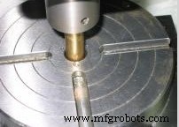
 |  Rough Position  Made a 3/8″ piece of brass and put a 60 degree point on it. It Should fit in the endmill holders. This method it to be quite useful for various setup operations.
|
|
 |  Visual Position  To perform a visual position. Your eye is pretty good and judging when the two circles are centered. Normally within 0.010″ Sometimes.
|
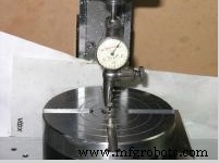
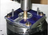
|  Indicate  To get a really accurate, to dial indicate in the rotary table. In the photo it looks like the tip of the indicator is hanging in space, but it is actually touching the back of the hole in the rotary table. I then run the table through 360 degrees of rotation watching for the maximum deflection on the indicator. Then rotate the spindle 90 degrees to the left and 90 degrees to the right. The true center will be half way between the two readings. For the final adjusting for centering that on the same side of the backlash as will be using when cutting. So if the cutter moves from the center to the right side, then want the cutter moving in the same direction when doing the center adjustment. If on the wrong side of the backlash, then well be overcompensate and start over now coming from the correct side.
|
|
 |  Lineup Jig To locate a jig or workpiece on the rotary table. I start off with the initial rough line up.
|
|
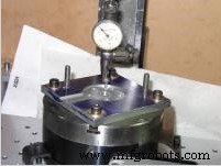 |  Indicate Jig  Centering the jig or workpiece over the center of the rotary table. To do this, rotate the rotary table and adjust the work piece until I get consistent run out all the way around.
|
To Center a Workpiece with the Rotary Table
Often it is necessary to perform a rotary table operation on several identical workpieces, each having a machined hole in the center. To quickly align each workpiece, a special plug can be made to fit the center hole of the workpiece and the hole in the rotary table. Once the machine spindle has been aligned with the rotary table, each succeeding piece can be aligned quickly and accurately by placing it over the plug.
If there are only a few pieces, which would not justify the manufacture of a special plug, or if the workpiece does not have a hole through it center, the following method can be used to center the workpiece on the rotary table.
1. Align the rotary table with the vertical mill head spindle.
2. Lightly clamp the workpiece on the rotary table in the center. Do not move the longitudinal(X) or crossfeed(Y) feed handles.
3. Disengage the rotary table worm mechanism.
4. Mount an dial indicator in the milling machine spindle or milling machine table, depending upon the workpiece.
5. Bring the dial indicator into contact with the surface to be indicated, and revolve the rotary table by hand.
6. With a soft metal bar, tap the workpiece(away from the indicator movement) until no movement is registered on the indicator in a complete revolution of the rotary table.
7. Clamp the workpiece tightly, and recheck the accuracy of the setup.
Radius Milling
To mill the end on the workpiece to a certain radius or to machine circular slots having a definite radius, following procedure below should be followed.
1. Align the vertical milling machine at 90* to the table.
2. Mount an dial indicator in the milling machine spindle.
3. Mount rotary table on the milling machine table.
4. Center the rotary table with the machine spindle using a test plug in the table and a dial indicator on the spindle.
5. Set the longitudinal(X)feed dial and the crossfeed(Y) dial to zero.
6. Mount the workpiece on the rotary table, aligning the center of the radial cuts with the center of the table. A special arbor may be used for this. Another method is to align the center of the radial cut with a wiggler mounted in the machine spindle.
7. Move either the crossfeed or the longitudinal feed(whichever is more convenient) an amount equal to the radius required.
8. Lock both the table and the saddle.
9. Mount the proper end mill.
10. Set the correct speed(RPM).
11. Rotate the workpiece, using the rotary table feed handwheel, to the starting point of the cut.
12. Set the depth of the cut and machine the radius to the size indicated on the drawing, using hand or power feed.
UNIT TEST
1. When is an offset boring head used?
2. Name three major components of Boring Heads.
3. Why is the locking screw tightened after tool slide adjustments have been made.
4. Why does the tool slide have multiple holes to hold boring tools?
5. What determines the cutting speed in boring?
6. For what purpose may a rotary table be used?
7. What is the purpose of the hole in the center of a rotary table?
8. Describe briefly how a rotary table may be centered with a vertical mill spindle.
9. Describe briefly how a single workpiece would be centered on a rotary table.
10. Explain how a large radius may be cut using a rotary table.
Chapter Attribution Information
This chapter was derived from the following sources.
- Tapping Procedures derived from Drilling and Tapping by the University of Idaho, CC:BY-SA 3.0.
- Tramming derived from Tramming Mill Head by the University of Idaho, CC:BY-SA 3.0.
- Dial Indicator (Photo) derived from Dial Gauge by Wikimedia, CC:BY-SA 3.0.
- Milling Machine Procedures derived from Mechanical Engineering Tools by the Massachusetts Institute of Technology, CC:BY-NC-SA 4.0.
- Rotary Table derived from Rotary Table by the University of Idaho, CC:BY-SA 3.0.
工业技术