

蓝牙控制的拾放机器人
组件和用品
 |
| × | 1 | |||
| × | 1 | ||||
 |
| × | 1 | |||
| × | 1 | ||||
| × | 1 | ||||
| × | 1 | ||||
| × | 1 | ||||
| × | 1 | ||||
 |
| × | 1 |
必要的工具和机器
 |
|
应用和在线服务
 |
| |||
 |
|
关于这个项目
介绍
本教程演示了如何构建一个由您的 Android 智能手机控制的拾放机器人。我们已经使用 MIT App Inventor 平台构建了一个移动应用程序。在本教程中,我们将分别讨论这个项目的每个部分。我们将讨论:
- 1 如何控制伺服电机
- 2 如何控制直流电机
- 3 如何使用蓝牙模块
- 4 如何用手机控制机器人
所以我希望本教程涵盖您构建机器人的所有需求。
场景
首先,我们必须知道机器人将如何接受订单。我们正在使用一个蓝牙模块,该模块将连接到我们将在之后构建的移动应用程序。现在我们需要知道我们将使用蓝牙连接通过手机向机器人发送命令。
硬件
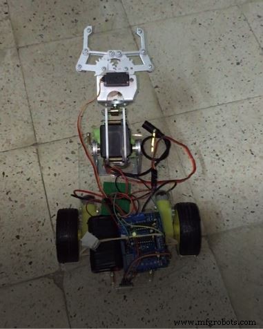
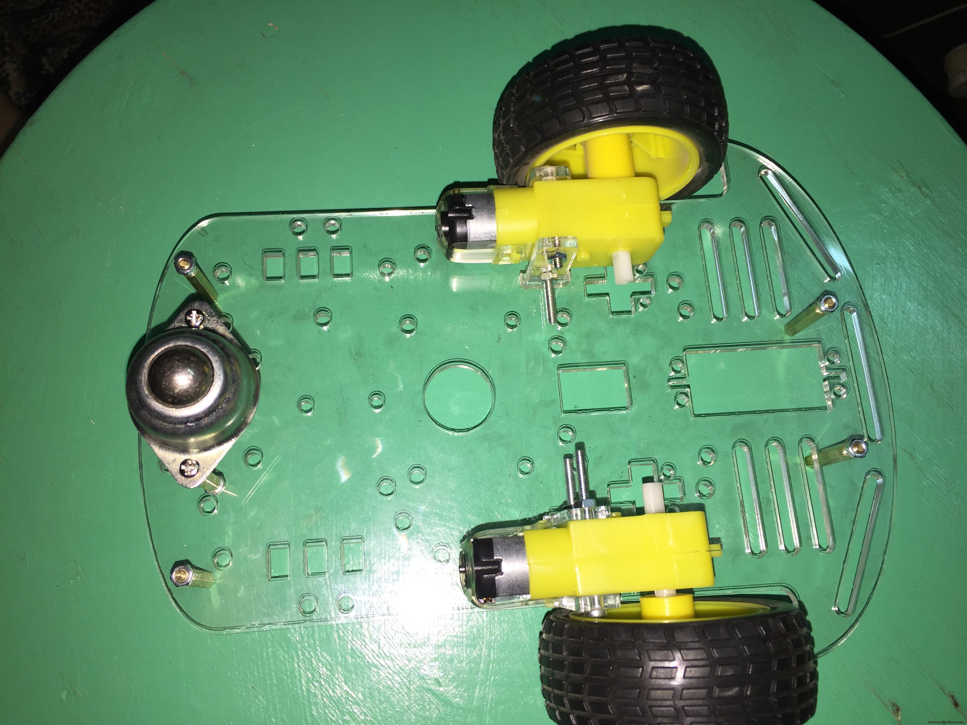
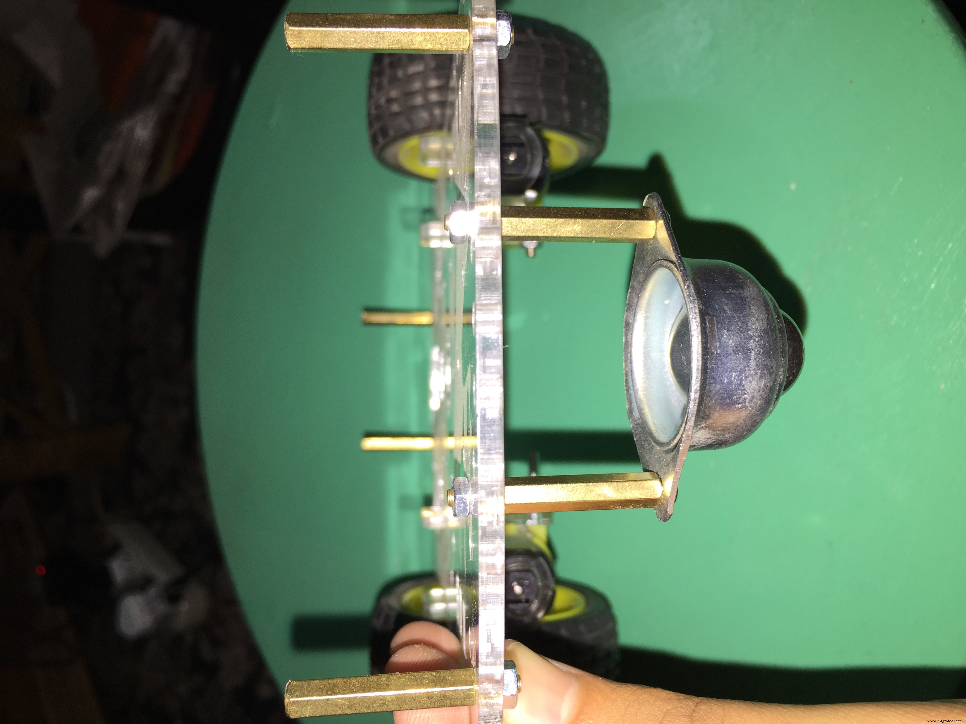
- 该套件需要一些简单的组装,但确实需要一些时间。按照套件随附的说明进行组装,
在程序集结束时,它应该是这样的:
Motor Shield 可让您与您的电机对话。如果您将电机直接连接到 Arduino 板,它将引发火灾! 因为每个电机至少需要 80MA 但数字 Arduino 引脚可以提供的最大电流是 40MA,所以 不要 尝试将电机直接连接到您的 Arduino 板。
- 电机护罩 帮助您控制电机的方向(例如向前、向后和释放)。
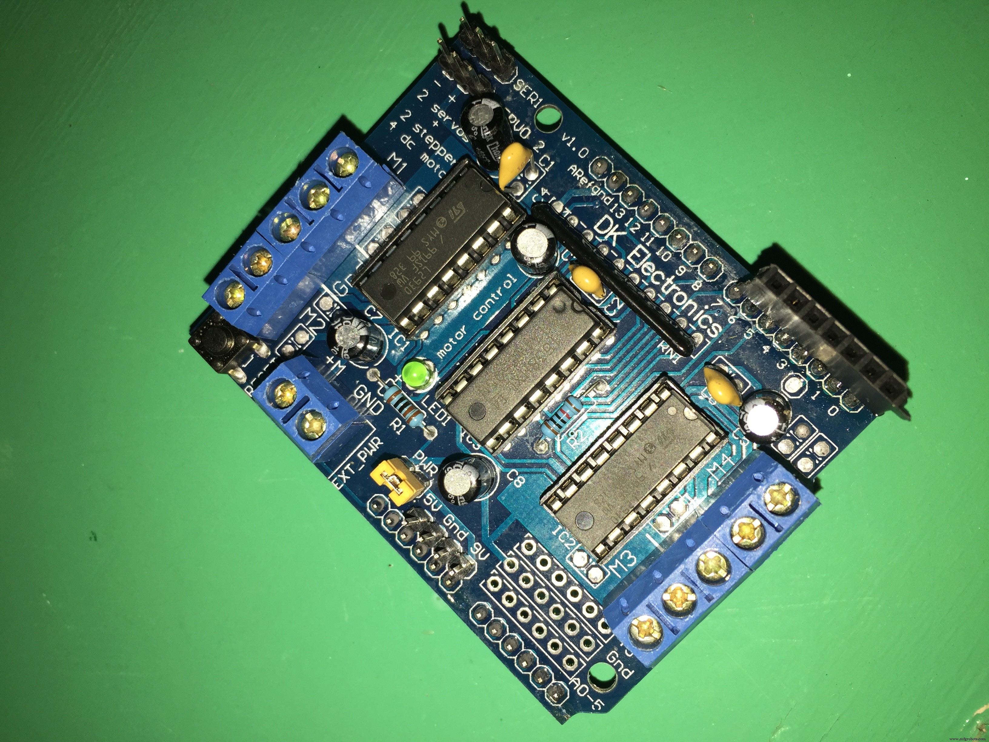
- 电机护罩 允许您控制最多 4 个双向 DC 具有单独 8 位速度选择的电机(因此,分辨率约为 0.5%)。
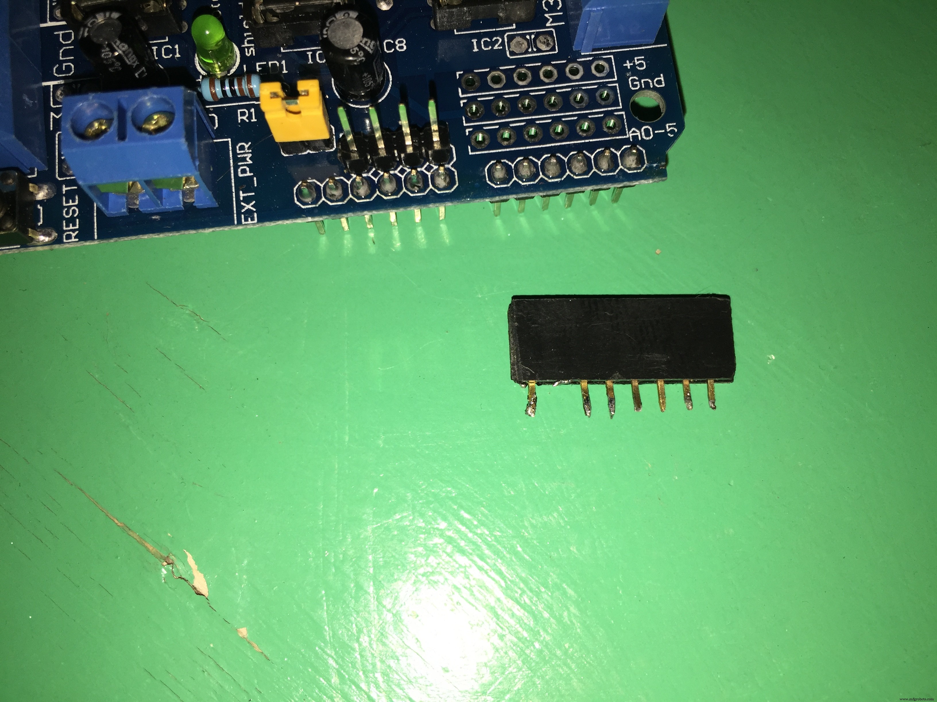
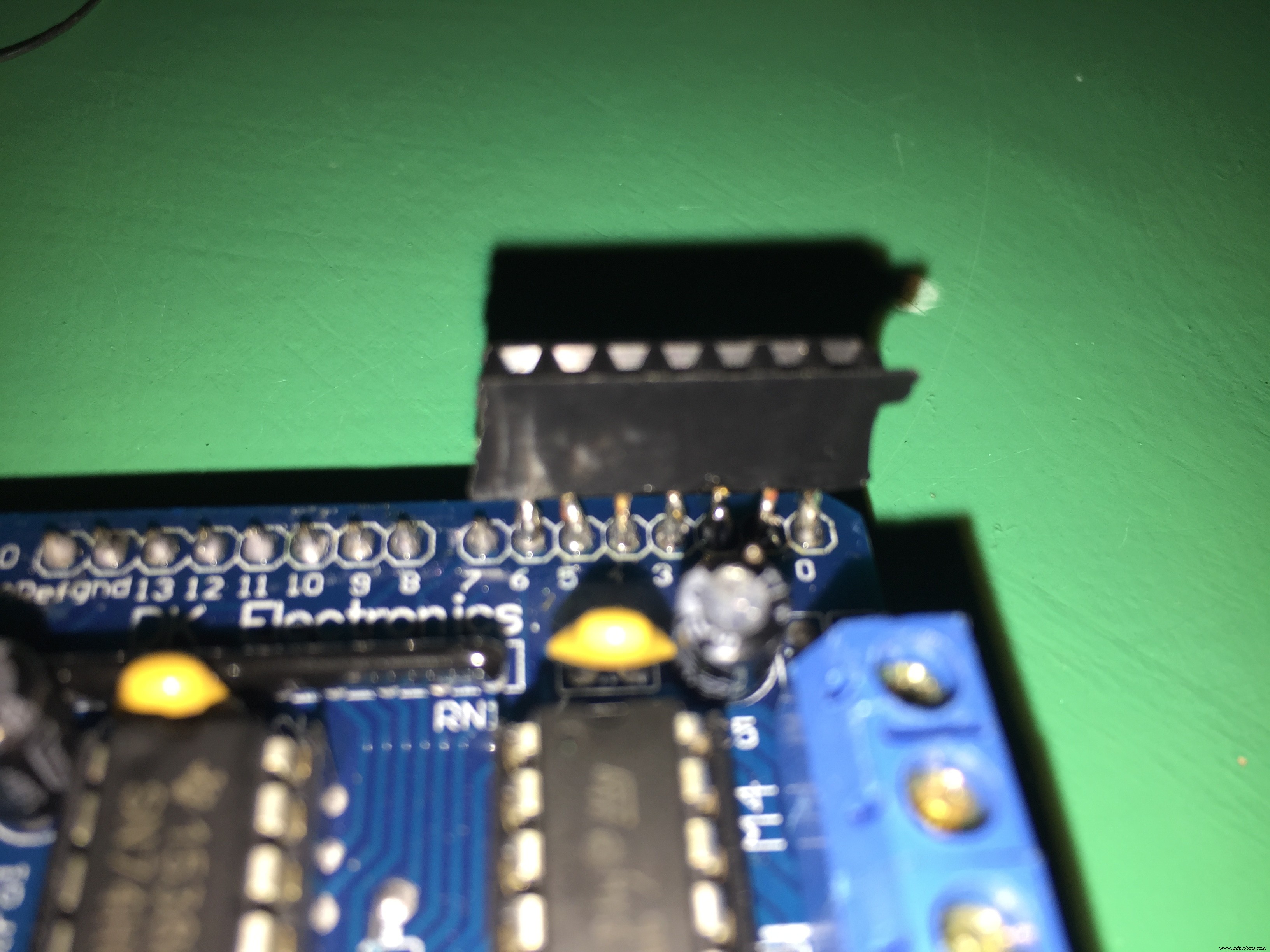
您可以在屏蔽顶部焊接一些排针,以便能够使用 Arduino 针脚。
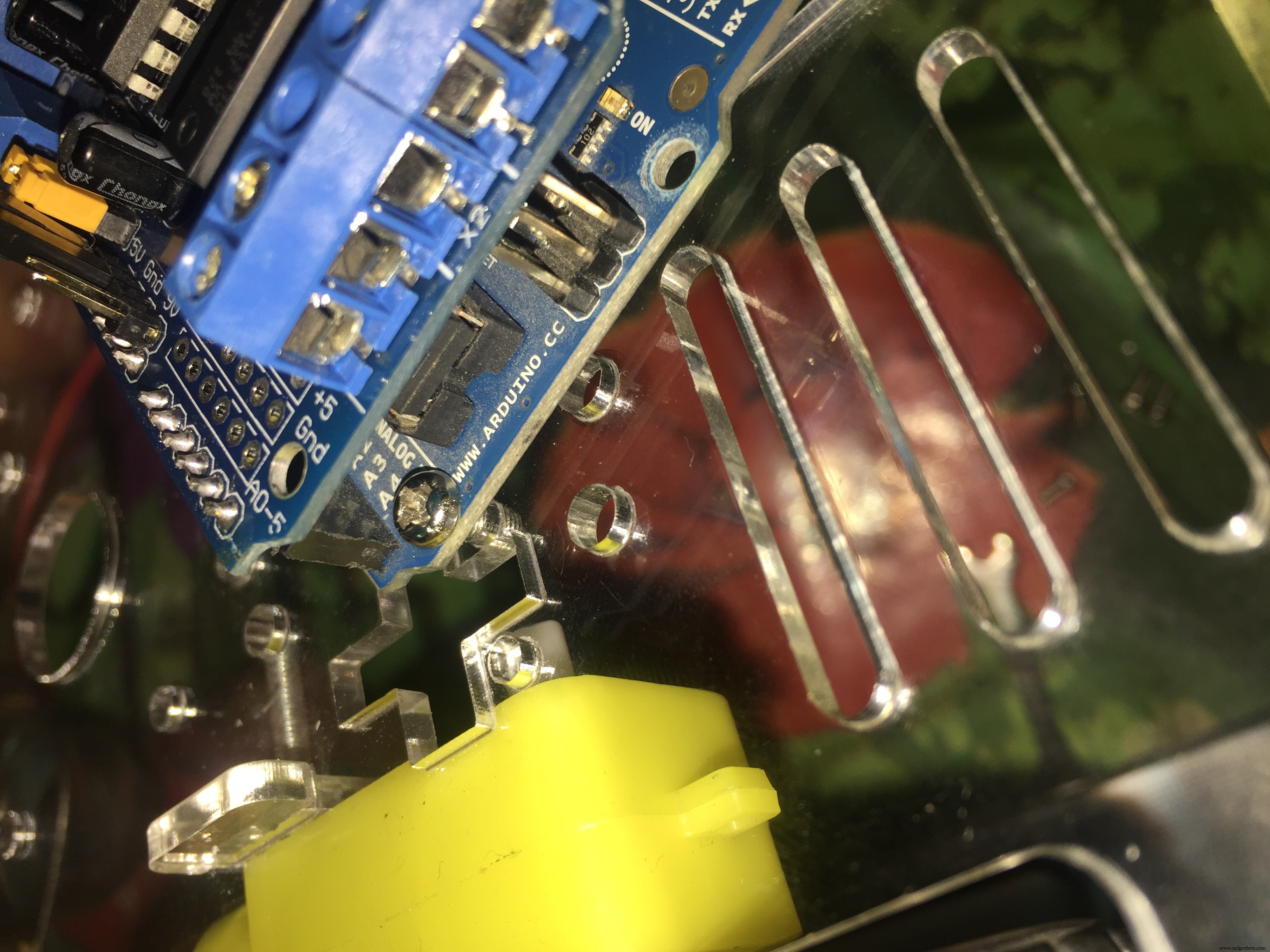
您需要像这样将电机防护罩贴在 Arduino 板上方:
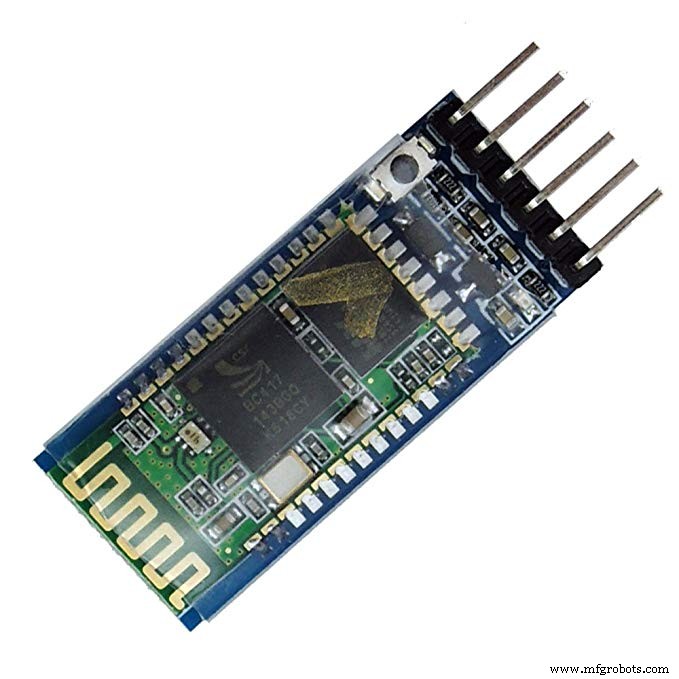
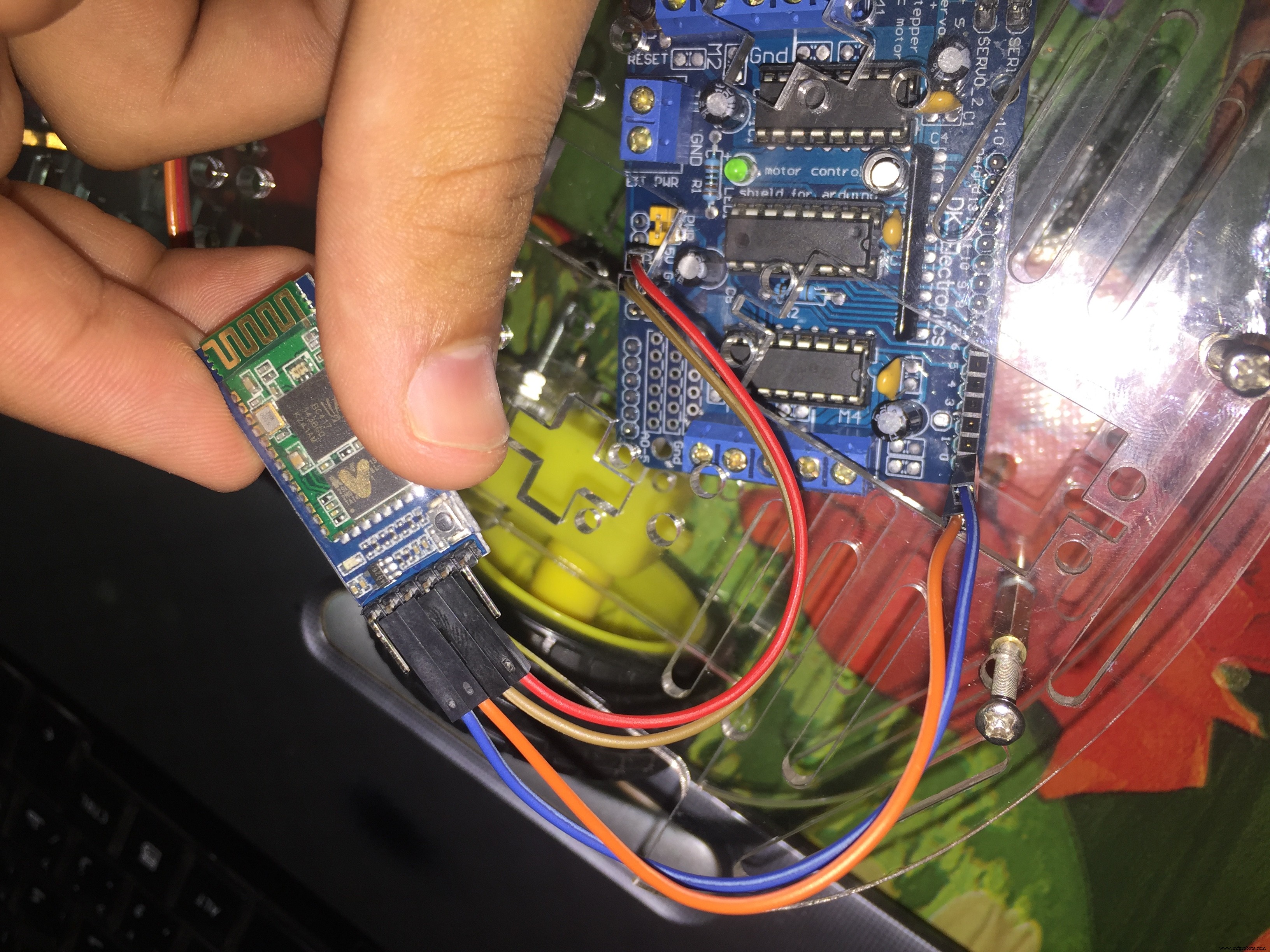
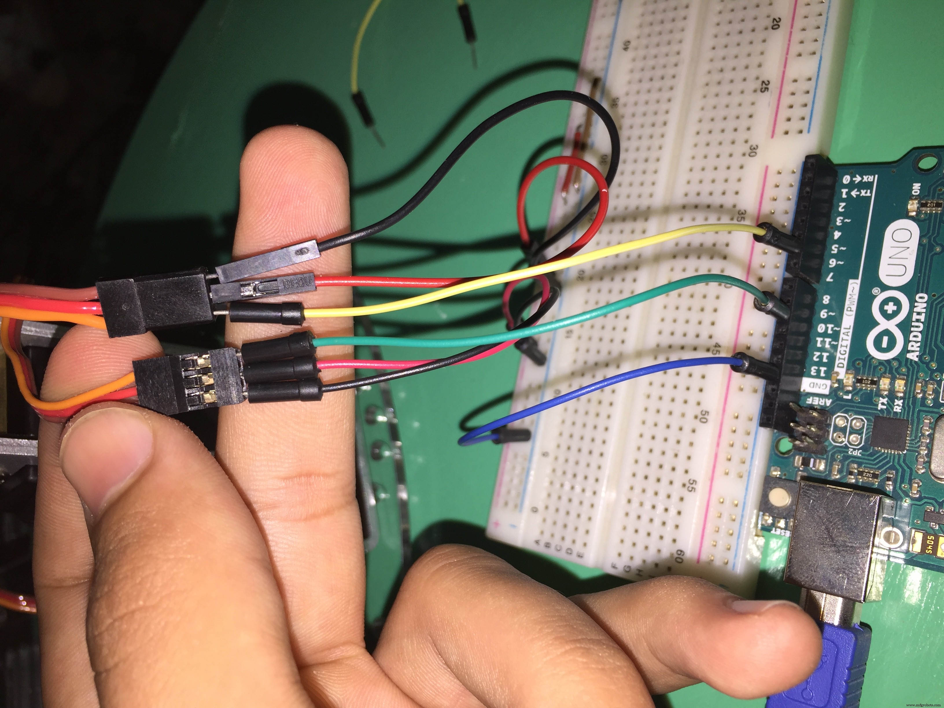
蓝牙模块 :它是飞行员和机器人之间发送命令和采取行动的渠道。
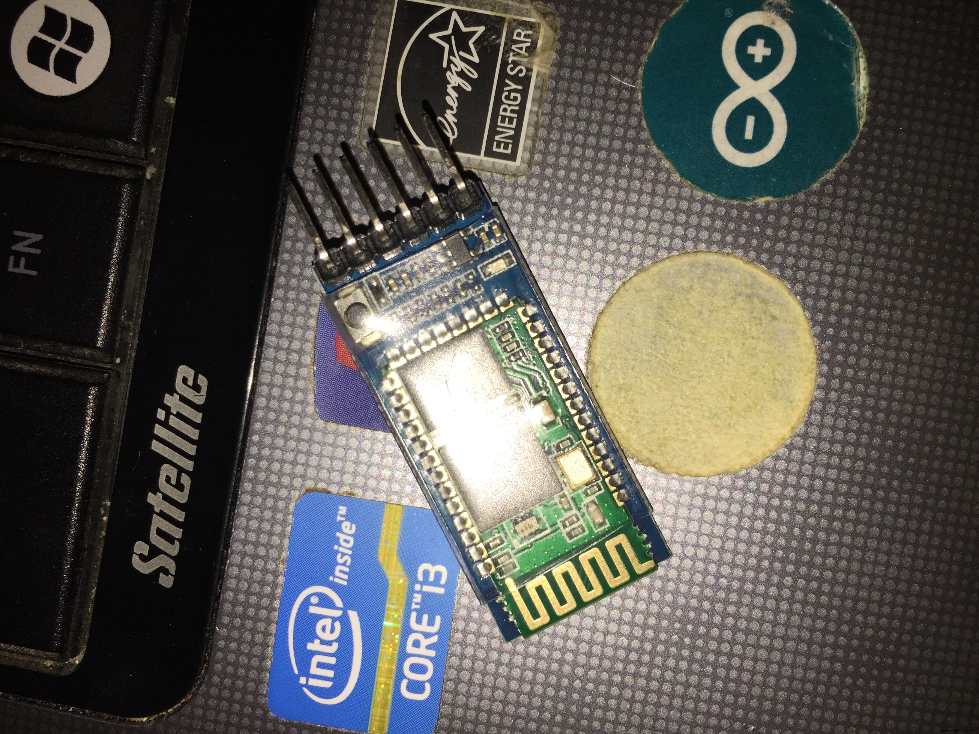
它有 6 个引脚;我们将只使用中间的四个引脚(RX-TX-GND-+5):

我们将连接:
- 蓝牙模块上的+5到Arduino上的5v
- 蓝牙模块上的GND到Arduino上的GND
- 蓝牙模块上的 Rx 到 Arduino 上的 Tx
- 蓝牙模块上的 Tx 到 Arduino 上的 Rx
注意:为什么是 Rx 到 Tx 和 Tx 到 Rx?
因为蓝牙模块发送数据(Tx),Arduino接收这个数据(Rx)。
一个发送,另一个接收
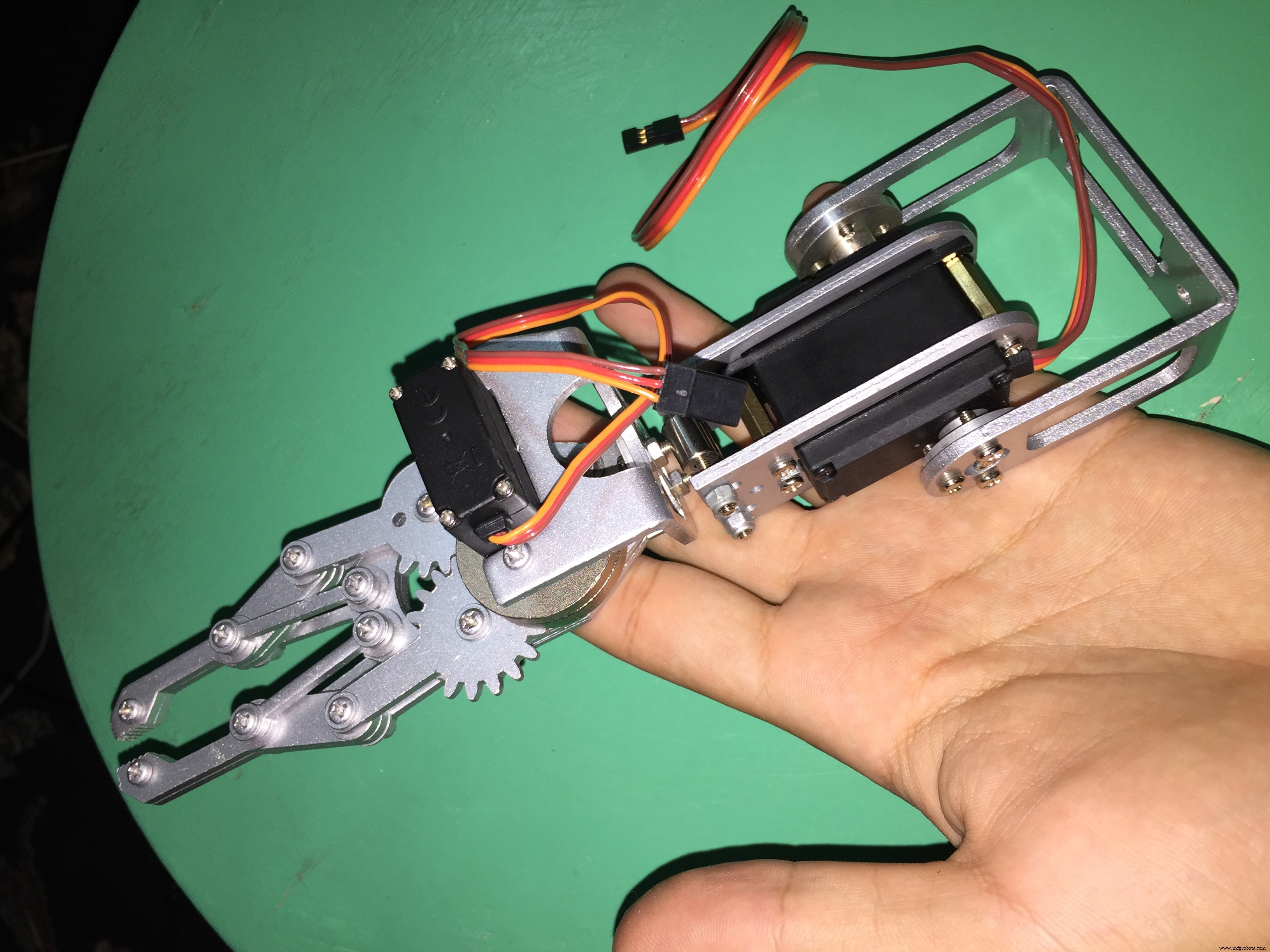
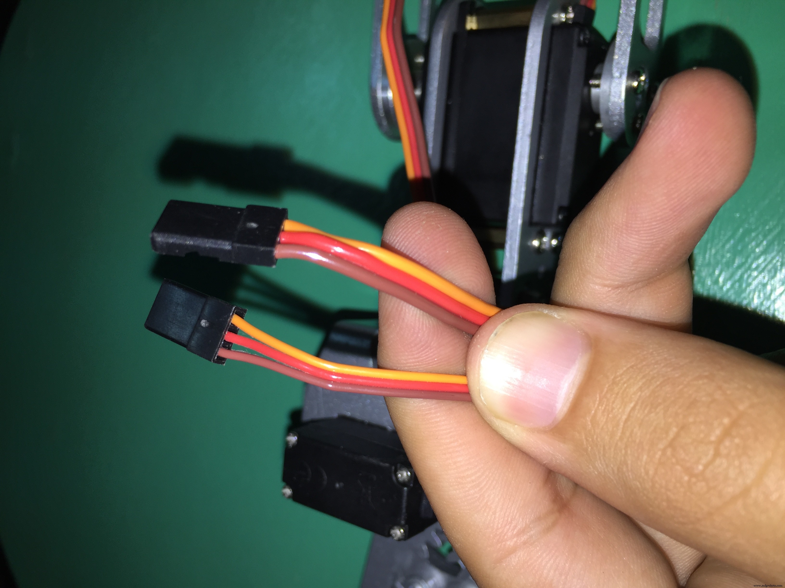
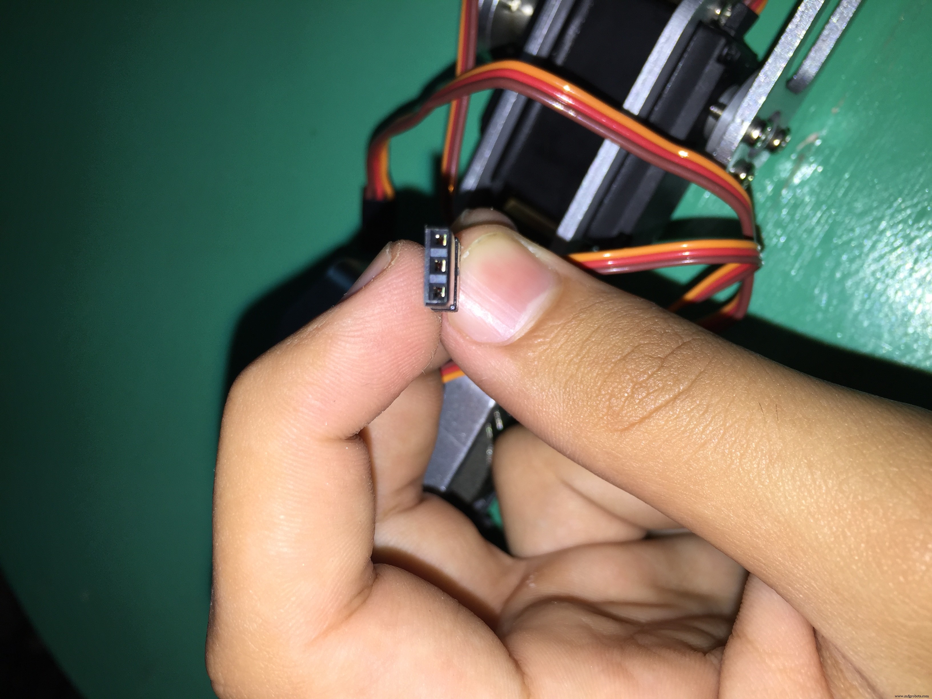
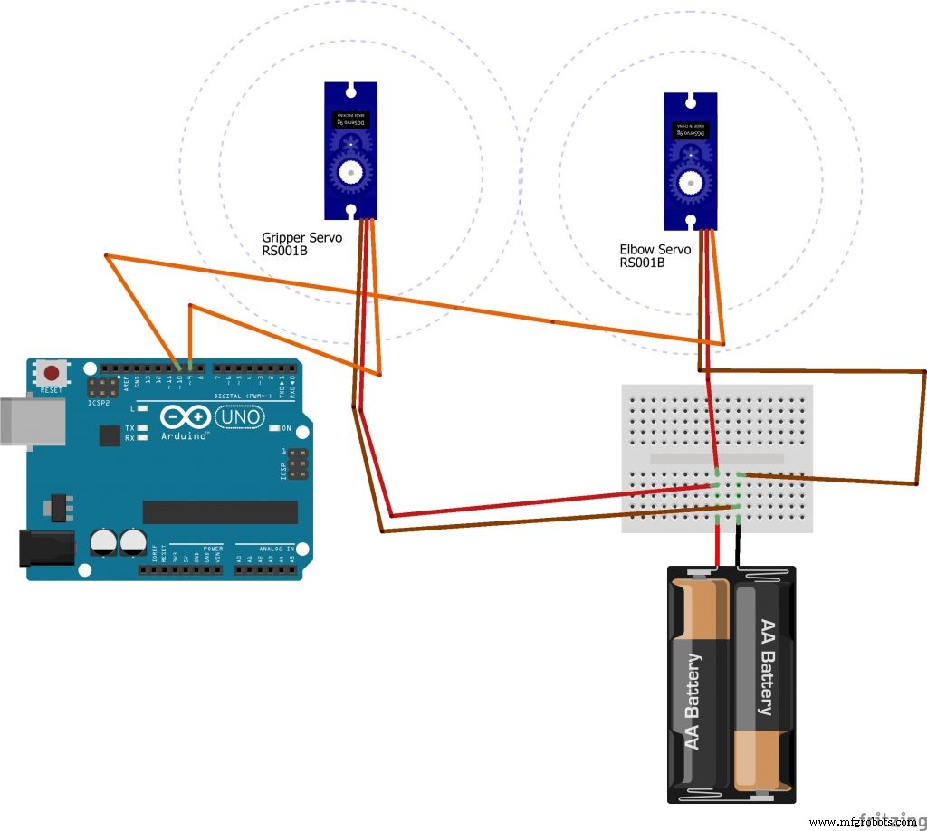
4)伺服电机有3根线:红色(正极)、棕色(负极)、黄色或橙色(信号)。
注意:做 请勿将伺服电机的正极和负极连接到 Arduino 板的 5V 和 GND。 Arduino 板将 生火 由于电机吸收的大电流;使用 外接电池。
- 外接电池正极的红线
- 棕色线连接到外部电池的负极
- 橙色线连接到 Arduino 上的任何数字 (PWN) 引脚
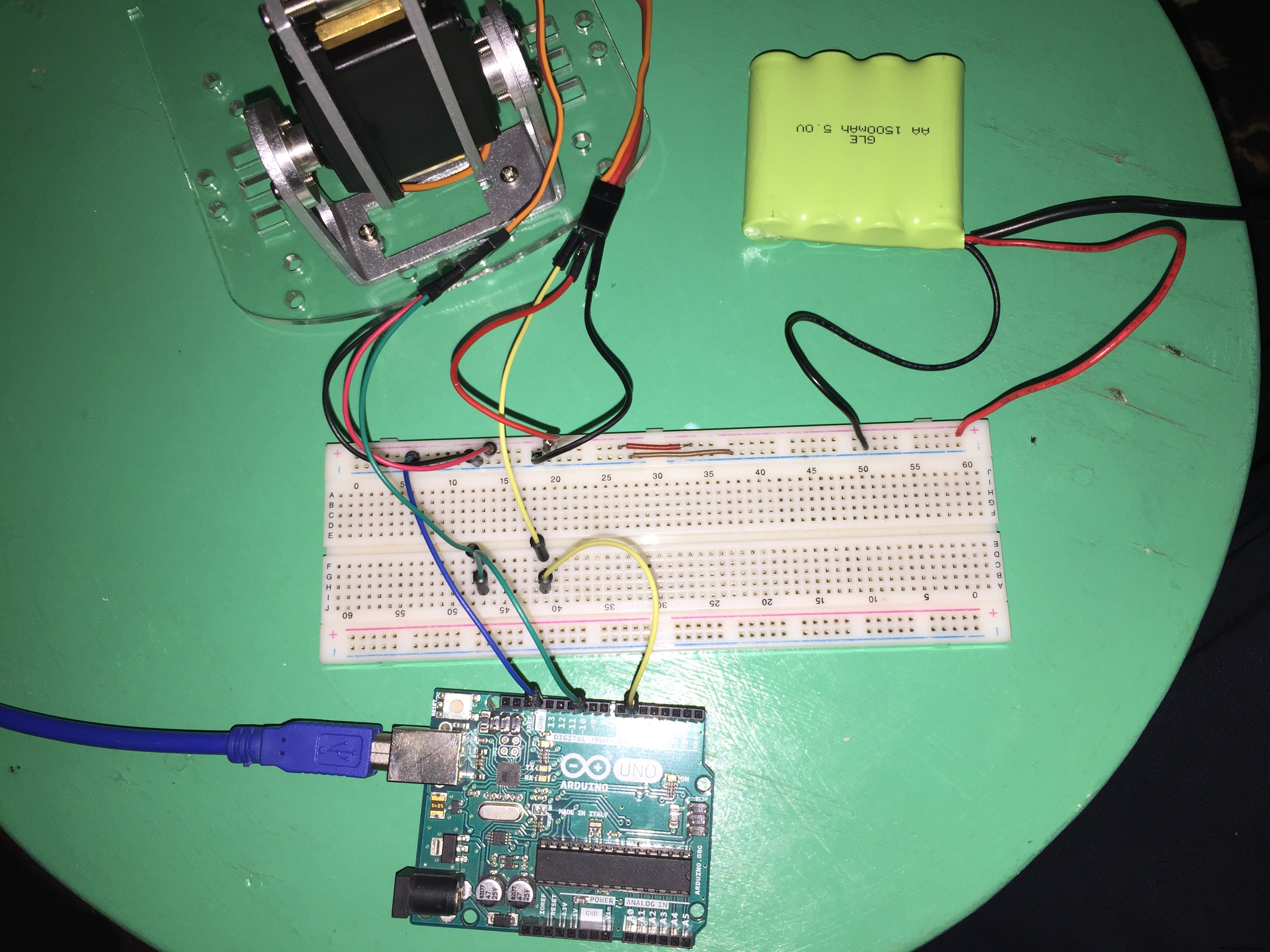
注意:不要忘记将电池的 GND 和 Arduino 的 GND 设为公共端,通过将每个 GND 相互连接来实现。
5) 直流电机
您需要在电机端子上焊接一些电线才能使用这些电机。
直流电机没有极性。没有正面也没有负面。如果您颠倒电机连接,电机的运动方向将会改变。

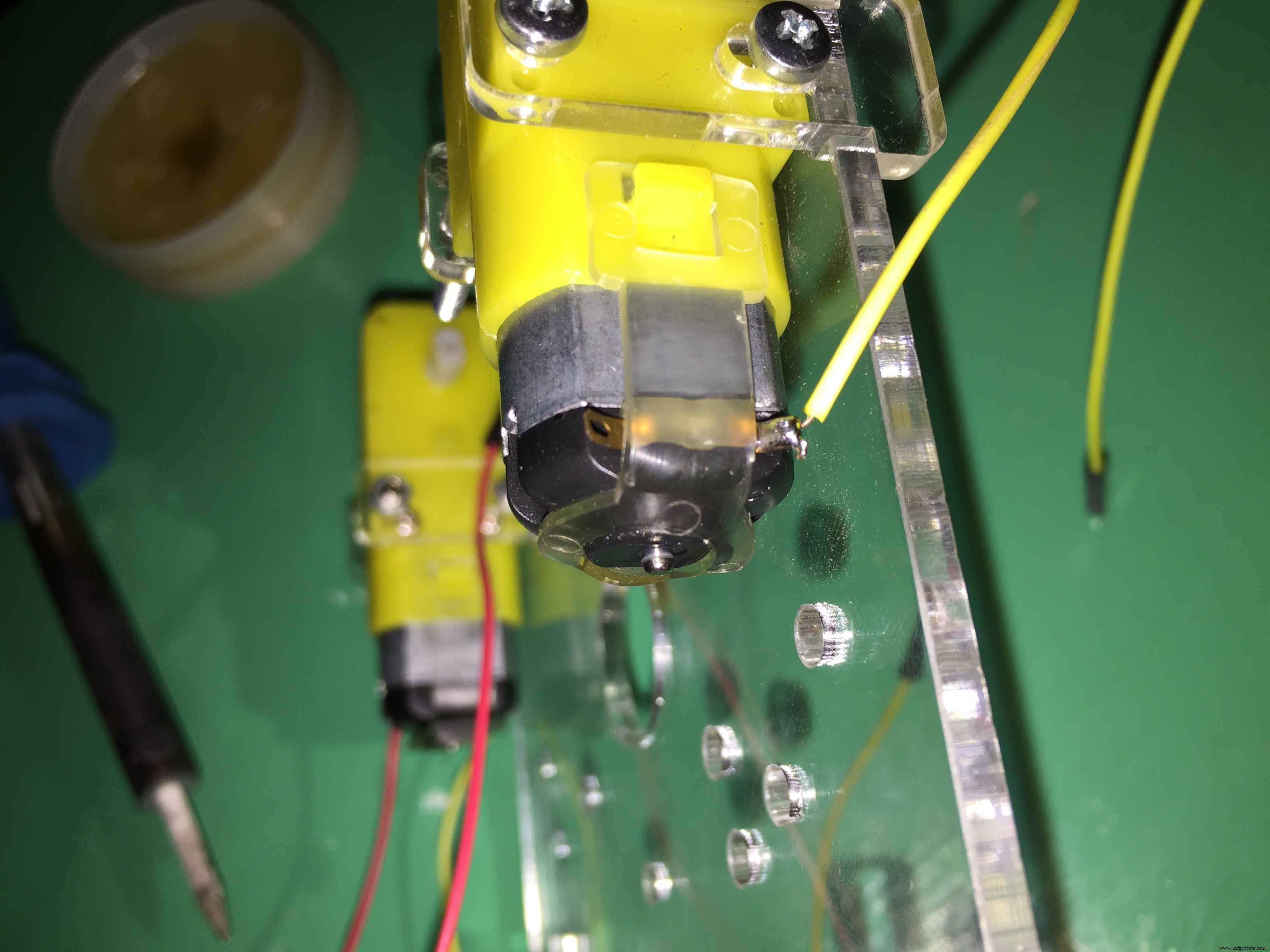
焊接电机端子后,将这些端子连接到电机屏蔽。

注意:在 t他的Arduino代码,我 使用电机 1 和电机 2 - 不是电机 3 和电机 4。
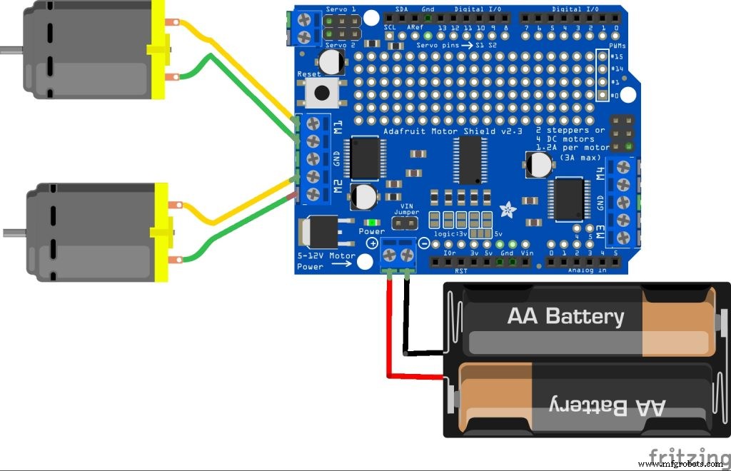
示意图
如何将机器人电机和电池与电机驱动器连接起来。
Arduino板如何连接Arm伺服电机和电池。
如何将蓝牙模块与Arduino板连接。
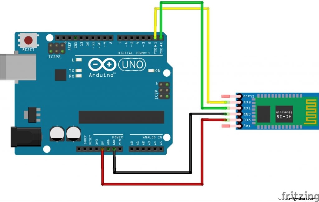
注意:在将代码上传到 Arduino 板的同时断开(移除红线 +5 针)蓝牙模块。然后在上传过程完成后重新连接。
代码
- 拾取和放置机器人 Arduino 代码
拾放机器人Arduino代码Arduino
#include#include AF_DCMotor motorR(1);AF_DCMotor motorL(2);伺服肘部伺服;伺服夹具伺服;int命令;void setup() {gripperServo.attach(9);肘部伺服.附加(10);串行开始(9600);motorR.setSpeed(255);motorL.setSpeed(255);}void loop(){command =Serial.read(); /* ARM 代码 */if(command>=1 &&command <=180) //elbow 伺服根据 mob 应用程序上的拇指位置在 0 - 180 之间移动 .{肘伺服.write(command);}else if ( command ==205) //Gripper 移动到角度 0{ gripperServo.write(0);}else if (command ==206) //Gripper movw 到角度 90{gripperServo.write(90); }else if (command ==207) //夹具移动到角度 180{gripperServo.write(180);} /* CAR CODE */ else if (command ==200){ motorR.run(FORWARD); motorL.run(FORWARD);}else if(command ==201){ motorR.run(FORWARD); motorL.run(向后); }else if(command ==202){ motorR.run(RELEASE); motorL.run(RELEASE); }else if(command ==203){ motorR.run(BACKWARD); motorL.run(前进); }else if(command ==204){ motorR.run(BACKWARD); motorL.run(向后); }else if(command ==0){ motorR.run(RELEASE); motorL.run(RELEASE); }}
示意图
此应用程序仅在 Android 手机上运行。你必须在使用这个应用程序之前打开蓝牙
在您从应用程序中选择蓝牙模块之前,请在您的手机设置中将您的手机与蓝牙模块配对 ieee_aast_aswan_test1_xVVlPTtt8n.apk
制造工艺