

纳米切割过程中流体介质对单晶铜材料去除和次表面缺陷演变的影响
摘要
通过分子动力学模拟研究了流体介质对单晶铜纳米切割过程中材料去除和亚表面缺陷演化的影响。本文通过分析水介质纳米切削过程中工件的原子迁移和位错演化,研究切屑的去除机制和加工表面的形成机制。研究了温度分布和次表面缺陷晶体结构转变,采用中心对称参数和常用邻域分析方法对其进行了分析。结果表明,工件材料在刀具的挤压剪切作用下被去除。水介质的润滑可以降低切削力,降低切屑高度。特别是流体介质的冷却作用导致在工件表面形成典型的“类似晶界”缺陷。并且随着流体介质的使用,纳米切割过程中工件的温度有明显的降低。
背景
金刚石切割被广泛认为是产生具有亚微米尺寸精度和纳米表面光洁度的纳米结构表面的有效技术[1]。纳米尺度的材料去除和加工表面形成机制对于提高纳米切削过程中的加工精度至关重要。在早期的研究中,研究人员主要关注材料的变形[2,3,4]、表面缺陷演变[5,6,7]、残余应力[8、9]和晶相转变[10, 11] 在真空环境中的纳米切割过程中。然而,在金属材料的实际纳米切削中,冷却和润滑液的作用对于提高加工性能至关重要[12]。因此,有必要研究流体介质对纳米切削过程中材料去除和亚表面缺陷演化机制的影响。
近年来,通过分子动力学(MD)模拟对纳米切削过程的加工机理进行了广泛的研究,被证明是研究纳米切削过程的有效方法。例如,Fang [13] 研究了恢复和侧流对表面生成和纳米切割中的相变的影响。并且发现抑制侧流是改善纳米切削中产生的表面粗糙度的有效途径。 Urbassek [14] 采用 MD 模拟研究纳米晶金属的划痕,发现晶粒取向对堆积形状产生主要影响,并且对摩擦系数也有很大影响。 Sharma [15] 研究了六种不同的晶体取向对纳米级切割中材料变形机制、次表面缺陷、切削力、比切削能量、犁形效应和表面粗糙度的影响。罗 [16] 通过在金刚石车削中使用纳米级多尖端金刚石工具证明了形状的可转移性,以扩大纳米结构的制造。
通过合理选择切削参数,如切削方向、切削深度、切削速度和刀具几何形状,可以抑制纳米部件的亚表面缺陷形成和表面粗糙度。然而,从产生机制上不能成功抑制表面缺陷的形成和提高表面质量。此外,这些研究主要集中在真空环境下的纳米切割工艺。实际上,在纳米切削中,刀具与工件之间存在大气和冷却液介质,这些介质会影响纳米切削机理和纳米结构的表面质量。
基于以上考虑,许多学者开展了利用流体介质进行纳米加工的研究。例如,Mylvaganam[17]利用MD模拟探索了O2对金刚石立方硅纳米压痕的影响,发现O2分子解离为氧原子并与硅原子形成化学键。 Rentsch [18] 发现切削液对应力和温度的分布有很大影响,并指出切削液可以减少刀具磨损。 Liu [19] 研究了大气分子对纳米切削表面质量和刀具磨损的影响。结果表明,由于大气分子的润滑,切削力降低,刀具磨损减少。 Singh [20] 研究了纳米颗粒切削液对金属去除过程的影响。 Wang [21] 讨论了水分子对纳米压痕过程中摩擦学行为和性能测量的影响,发现水分子的参与使得初始压痕力增加而最大压痕力减小。 Chavoshi [22] 研究了还原氧条件下单晶硅的高温纳米划痕,模拟中没有观察到高压硅相的残留。
从现有文献来看,以往关于流体介质纳米切削加工的研究都是基于少数分子或纳米粒子的模拟模型,其位于刀具-芯片界面区域。但在其他方面没有加入流体介质,对流体介质的润滑分析也很有限。由于模型中流体介质不足,流体介质的冷却作用不影响纳米切削过程,而流体介质的冷却作用与润滑作用对加工精度和表面质量同样重要。
因此,在本文中,刀具和工件完全被切削液介质包围,切削液介质不仅存在于刀具-切屑界面的作用区,还存在于工件表面、加工表面和后部区域。的工具。因此,可以研究切削刀具和工件之间流体介质的充分润滑。此外,在纳米切割过程中,流体介质被设置为恒温,流体介质的冷却作用也可以很好地研究。水基切削液广泛应用于超精密加工过程中,它不仅含有水,还含有可溶性基础油、蓖麻油、三乙醇胺、硼酸、表面活性剂、聚乙二醇、磷酸钠等。然而,切削液的主要成分是水介质,切削液中水的质量分数达到70%左右。由于其他物质的MD模型难以建立,且势函数参数未知,因此无法通过分子动力学计算模拟方法进行水基切削液纳米切削的研究。因此,在纳米切削过程模拟中,本研究采用切削液的主要成分水介质代替水基切削液。在建立的MD模型的基础上,进行纳米切割工艺,研究水介质对材料去除和次表面缺陷形成机制的影响。采用中心对称参数(CSP)、公共邻域分析(CNA)和位错提取算法(DXA)方法研究了次表面缺陷演化、切削力变化、工件温度分布和次表面缺陷晶体转变.
方法
仿真模型
为了研究流体介质对纳米切削中材料去除和亚表面缺陷演化的影响,建立了有和没有水介质的MD模型,如图1所示。在模型中,水分子是根据TIP4P 模型 [23,24,25]。 CHARMM 力场和 Lennard-Jones (L-J) 势函数用于精确计算水分子的运动。可以综合分析非键势能、键膨胀势、键角弯曲势能、分子振动的影响,使水分子的模拟更加准确。工件材料为单晶铜,加工刀具为金刚石材料。它包含62835个水分子、368208个Cu原子和2452个C原子。工件分为牛顿层、温度层、边界层三部分。为了减少尺寸效应,在[001]和[010]处采用周期性边界条件(PBC)。为了保持水介质的压力和密度,在[001]方向的两侧都使用了反射墙。在实际加工过程中,冷却液带走了大部分切削热,因此本工作将水环境设置为恒温300K。具有真空环境的MD模拟模型如图1b所示,其中初始模拟条件与流体环境模型相似。两个模型之间的不同设置是水介质的相关设置。详细切削参数如表1所示。
<图片>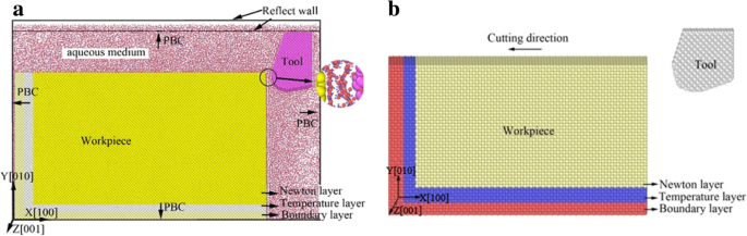
纳米切削中的MD模拟模型。 一 水介质的使用。 b 真空环境的使用
原子间势函数
在MD模拟中,势函数对模拟结果起着决定性的作用。材料特性从根本上由原子之间的相互作用控制。在本研究中,模型分为工件、刀具和水介质三部分,包含四种原子类型,分别是Cu、C、H和O原子。不同原子之间的相互作用通过莫尔斯势、嵌入原子法 (EAM) 势、Lennard-Jones (L-J) 势和 Tersoff 势计算。不同原子间选定势函数的详细介绍如表2所示。
莫氏电位
工件中的铜原子与刀具中的碳原子之间的相互作用由莫尔斯势计算,如式(1)所示。 (1) [26]。
$$ u\left({r}_{ij}\right)=D\left[\exp \left(-2\alpha \left({r}_{ij}-{r}_0\right)\right )-2\exp \left(-\alpha \left({r}_{ij}-{r}_0\right)\right)\right] $$ (1)其中 r 0, α , 和 D 分别是原子间距、弹性模量和结合能。 r 的值 0, α , 和 D 如表3所示。
EAM 潜力
工件中铜原子之间的原子间函数用 EAM 势来描述,如方程 1 所示。 (2) 和 (3) [27, 28]。
$$ E\kern0.5em =\kern0.5em \sum \limits_i^N\left[F\left({\rho}_i\right)\kern0.5em +\kern0.5em \sum \limits_{j\kern0 .5em>\kern0.5em i}^Nu\left({r}_{ij}\right)\right] $$ (2) $$ {\rho}_i\kern0.5em =\kern0.5em \sum \limits_jf\left({r}_{ij}\right) $$ (3)伦纳德-琼斯潜力
Lennard-Jones 势函数是一个双势函数,它包括原子间长程库仑力和短程范德华力的相互作用。 L-J 势常用于模拟液体材料。本文采用Lennard-Jones势来计算水分子与其他原子之间的相互作用,如式(1)所示。 (4) [29]。
$$ {U}_{LJ}(r)\kern0.5em =\kern0.5em 4\varepsilon \left[{\left(\frac{\sigma }{r}\right)}^{12}\kern0 .5em -\kern0.5em {\left(\frac{\sigma }{r}\right)}^6\right] $$ (4)其中 σ 是当相互作用势能为零且 ε 时的平衡分离 是势能陷阱的深度。
对于不同的材料,σ 和 ε 可以通过方程计算。 (5)和(6)[29]。
$$ {\sigma}_{\alpha \beta}\kern0.5em =\kern0.5em \frac{\sigma_{\alpha \alpha}\kern0.5em +\kern0.5em {\sigma}_{\beta \beta}}{2} $$ (5) $$ {\varepsilon}_{\alpha \beta}\kern0.5em =\kern0.5em \sqrt{\varepsilon_{\alpha \alpha}\cdot {\varepsilon }_{\beta \beta}} $$ (6)本研究中使用的原子间L-J势参数如表4所示。
特塞夫潜力
金刚石工具中碳原子之间的相互作用由 Tersoff 势计算,如方程式 1 所示。 (7)和(8)[30]。
$$ E\kern0.5em =\kern0.5em \frac{1}{2}\sum \limits_{i\ne j}{V}_{ij} $$ (7) $$ {V}_{ij }\kern0.5em =\kern0.5em {f}_c\left({r}_{ij}\right)\left[{V}_R^{\hbox{'}}\left({r}_{ ij}\right)\kern0.5em +\kern0.5em {b}_{ij}{V}_A\left({r}_{ij}\right)\right] $$ (8)其中 f c (r ij ) 是原子间的截断函数,V A (r ij ) 是吸收项的双势,V R (r ij ) 是排斥项的对偶势,r ij 是原子 i 之间的原子距离 和原子 j .
缺陷分析方法
在单晶铜的纳米切割中,变形和位错在工件的亚表面成核。在本文中,引入中心对称参数(CSP)来分析工件的位错形核和缺陷演化。对于面心立方 (FCC) 材料,CSP 值可以通过公式计算。 (9) [31]。
$$ CSP\kern0.5em =\kern0.5em \sum \limits_{i\kern0.5em =\kern0.5em 1}^6{\left|{R}_i\kern0.5em +\kern0.5em {R }_{i+6}\right|}^2 $$ (9)其中 R 我 是具有相同距离和 R 的相邻原子 i + 6 是具有相反方向的相邻原子。 FCC 晶体、部分位错、堆垛层错和表面原子的 CSP 值分别为 0、2.1、8.3 和 24.9 [32]。典型晶体结构和原子颜色的CSP值范围如表5所示。
CSP方法能够识别原子构型,但不能识别工件的局部原子晶体结构状态。因此,引入了公共邻居分析(CNA)来识别工件的局部晶体结构。在 Honeycutt [33] 提出的原始 CNA 方法中,各种结构用图表表示。目前在 OVITO 软件[34, 35]中改进了快速识别五种结构,分别是面心立方(FCC)、密排六方(HCP)、体心立方(BCC)、二十面体(ICO),未知。在本文中,还引入了位错提取算法(DXA)[36]来分析位错缺陷的演变。通过DXA方法,工件中不同的晶体结构会用不同的颜色标记,工件中的位错缺陷会用不同颜色的线条表示。
结果与讨论
水性介质纳米切割过程中的次表面缺陷演变
切割系统的剖面图如图2所示,其中包含纳米切割过程中的刀具、工件和水介质。为了清楚地感知工件的塑性变形,采用CSP方法对结果进行分析。快照部分由 CSP 值着色,如图 2 所示,其中图 2a 在切割距离为 5 nm,图 2b 在切割距离为 15 nm。可以看出,在单晶铜表面形成了一层致密的水膜,如图2a中的“单分子水膜”所示。水膜遍布刀具和工件表面,其中氧原子占据单晶铜晶格的中心。水分子的规则排列是水分子与铜原子之间长程库仑力和范德华力共同作用的结果。
<图片>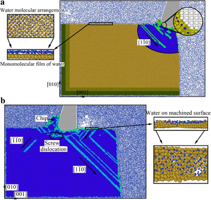
纳米切割过程中水介质切割系统的剖面图(彩色在线)。 一 切割距离 l =5nm。 b 切割距离 l =15nm
在纳米切削过程中,滑移变形是由刀具的早期压缩剪切作用引起的,并作为应变能储存在形成的晶格中。当应变能积累达到一定程度时,应变能被释放。然后,单晶铜的晶格重新排列,导致位错成核并沿\( \left[1\overline{1}0\right] \)方向延伸,如图2a所示。从图2a可以看出,在工件表面形成了水的单分子膜。此外,水分子在刀具 - 切屑界面的作用区域中渗透到工件的亚表面,如图 2a 中的右上图所示。由于存在于刀具与工件之间的水分子的润滑作用,刀具的压剪作用减弱。应变能积累减少,位错延伸不充分。此外,水介质带走了大量的切削热,形核位错膨胀的能量不足。因此,位错延伸不足,工件表面下位错线不明显,如图2a所示。
随着刀具向前运动,工件受到刀具后刀面产生的挤压和摩擦作用。在刀具的挤压和摩擦作用下,大量位错在工件表面形核并延伸。这些位错的一部分沿着前刀面向上移动,最终作为切屑被去除,如图 2b 所示。这些位错的另一部分沿刀具前刀面向下移动,在刀具后刀面挤压摩擦作用后转变为粗糙的加工面,如图2b所示为“加工面上的水排列”。 ”位错的其他部分沿着 \( \left[\overline{1}\overline{1}0\right] \) 和 \( \left[1\overline{1}0\right] \) 滑动平面向内移动并消失在工件内部,形成螺位错,如图2b所示。由于切屑高度逐渐增加,在切削过程的后期,切屑前面的水分子不能越过切屑流到刀具后面。并且刀具背后水介质的密度和压力迅速降低,导致纳米切削过程中切削热被不及时带走。因此,形核位错有足够的能量在工件内部延伸,如图2b所示。
为了阐明纳米切割过程中单晶铜的位错和局部原子晶体结构的潜在变形,引入了CSP和DXA分析方法。分析结果如图所示。 3、4、5、6,其中图图 3 和图 4 是根据 CSP 值和图 3 渲染的。 DXA分析结果为5和6着色。
<图片>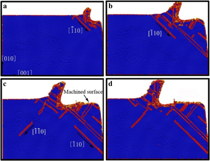
纳米切削过程中含水介质工件亚表面缺陷分布[J]. a的切割距离 , b , c , 和 d 分别为5 nm、8 nm、12 nm和15 nm。
<图片>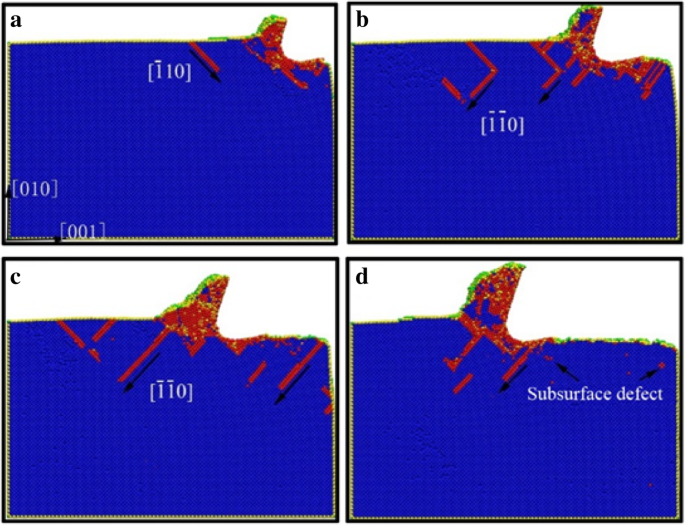
真空环境下纳米切削过程工件亚表面缺陷分布[J]. a的切割距离 , b , c , 和 d 分别为5 nm、8 nm、12 nm和15 nm。
<图片>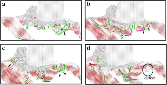
纳米切割初期工件的DXA图像。位错根据以下方案着色:深蓝色代表完美位错,绿色代表肖克利位错,粉色代表阶梯状位错,黄色代表赫斯位错,浅蓝色代表弗兰克位错,红色代表不明位错。 a的切割距离 , b , c , 和 d 分别为 7 nm、8 nm、9 nm 和 10 nm
<图片>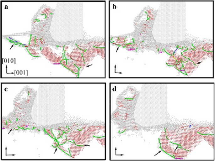
纳米切割后期工件的DXA图像。位错的着色方案与图5相同。a的切割距离 , b , c , 和 d 分别为 17 nm、18 nm、19 nm 和 20 nm
水介质纳米切削过程中工件的亚表面缺陷分布如图3所示,其中不显示水介质以更清楚地观察位错缺陷演变。黄色、绿色、红色和橙色区域分别代表表面原子、表面缺陷原子、位错原子和次表面缺陷原子。无水介质纳米切削过程中工件的位错分布及延伸如图4所示。从两幅图中可以看出,成核位错沿\( \left[\overline{1}10 \right] \) 水介质纳米切割过程中的滑移向量,但在真空介质下纳米切割中沿 \( \left[\overline{1}\overline{1}0\right] \) 滑移向量延伸.众所周知,刀具的剪切作用使位错沿逆着刀具的方向向前延伸,即\( \left[\overline{1}10\right] \)滑移矢量。刀具的摩擦作用导致位错沿刀具正运动方向迁移,这是一个\( \left[\overline{1}\overline{1}0\right] \) 滑移矢量。真空环境下的纳米切削加工过程中,刀具对工件的作用是前刀面的剪切作用和后刀面的摩擦作用,而后刀面的摩擦作用会引发加工表面和亚表面缺陷的形成。因此,在真空中纳米切割过程中,位错扩展沿\( \left[\overline{1}\overline{1}0\right] \) 滑移矢量扩展。由于刀具与工件之间存在水分子的润滑作用,减少了刀具的摩擦作用。因此,剪切作用在加工表面和次表面缺陷的形成中起着重要作用。因此,在水介质纳米切割中,位错主要沿\( \left[\overline{1}10\right] \)滑移矢量延伸。
从无花果。由图 3 和图 4 可以发现,在纳米切割过程中,水介质中次表面缺陷的规模大于真空中。实际上,位错缺陷遍布整个加工区域并深入工件内部。切削热被水介质带走,缺陷原子能量降低。因此,次表面缺陷没有足够的能量被消灭。因此,位错缺陷残留量增加。对于水介质的纳米切割工艺,次表面缺陷层的深度相对较高。由于水分子、碳原子和铜原子之间的相互作用,在加工表面的形成过程中,刀具与工件之间的挤压摩擦减弱,加工表面的原子无序加剧。此外,次表面缺陷残留加剧,次表面残余应力增大。
为了更好地揭示水介质对位错缺陷演化过程的影响,采用DXA方法对水介质纳米切削过程中的工件进行分析,其前期和后期如图5所示。和 6,分别。在纳米切割过程的早期发现加工表面下方的几层原子中存在稳定的晶体缺陷,位于两个堆垛层错之间,如图5d所示。晶体缺陷的存在会影响加工表面的质量,甚至会导致加工表面产生微裂纹。因此,对缺陷演化过程的形成进行了研究。从图 5a 可以看出,在缺陷形成的早期瞬间,在刀具后刀面的摩擦作用下,大量的肖克利部分位错形核。这些肖克利位错在刀具前进过程中演变成 V 形位错环,如图 5b 所示。随后,V形位错逐渐演变为系列肖克利部分位错。最后,局部位错转化为次表面的残余缺陷。由于切削热被水介质带走,缺陷原子的能量太小而无法被消灭,并转化为加工表面下方的不动的缺陷。加工表面的粗糙度会增加,次表面的残余应力会引起更多的恶化。此外,缺陷还可诱发表面微裂纹。
采用DXA方法研究了水介质在排屑过程中对刀具剪切滑移作用的影响,如图6所示。从图6a可以看出,大量的肖克利部分位错在切削过程中形核。切割工具的前面。而剪切滑移面就是由这些位错构成的。在接下来的切割过程中,连续的层错和部分位错在剪切滑移平面上成核并延伸。在刀具前方位错的形核和运动作用下,切屑沿剪切滑移平面逐渐被去除,如图6c所示。同时,由于水介质的润滑作用,刀具前刀面的挤压摩擦作用减弱。如图6a-d所示,在纳米切割过程中位错成核和传播不充分,次表面缺陷残留不明显。相应地,刀具对工件的剪切作用变得更加显着。因此,在纳米切割过程中,在水介质的参与下,形成的切屑更容易被去除。并且主切削力会同时减小,这将在本文后面详细讨论。
水介质对切削力和切削热变化的影响
在切削过程中,材料的去除是通过刀具的挤压和剪切作用来实现的。由于金属材料的强度、刚度和韧性,刀具的前刀面在材料去除过程中受到工件材料抵抗变形所产生的反作用力。而刀具后刀面受加工面摩擦阻力的影响。这些力共同构成了切削力。同时,切削屑的剪切变形以及刀具与工件之间的摩擦作用所施加的功转化为切削热,导致工件温度升高。随着材料应变能的积累和释放,工件表层发生位错形核和膨胀,引起切削力和切削热随切削距离的变化。
本研究中,水介质的参与对切削力和切削热的变化影响很大。使用和不使用水性介质的纳米切割过程中切割力随切割距离的变化曲线如图 1 和图 4 所示。如图 7 和 8 所示,其中黑色、红色和蓝色曲线分别是进给力 (Fx)、后退力 (Fy) 和切向力 (Fz)。由于在 Z 方向采用 PBC 并且金刚石工具在模拟中沿 Z 方向为柱状,因此平均切向力(Fz)在两个图 3 中都处于 0 nN 的水平。 7 和 8。
<图片>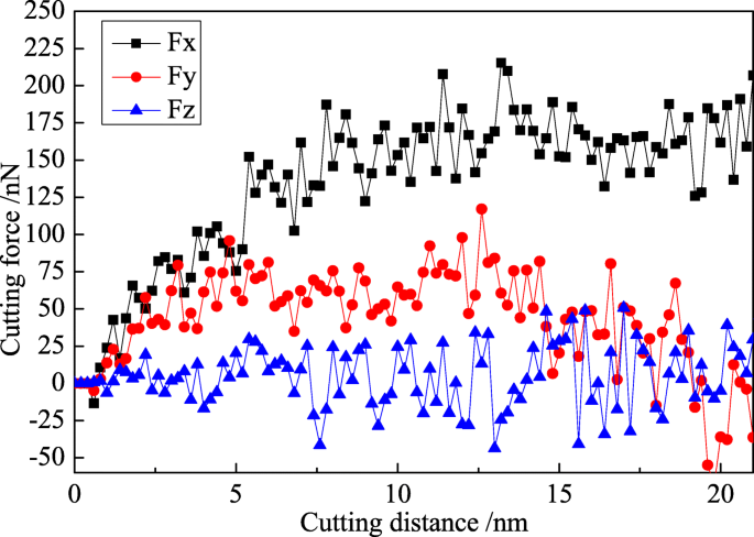
真空环境下纳米切削中切削力的变化曲线
<图片>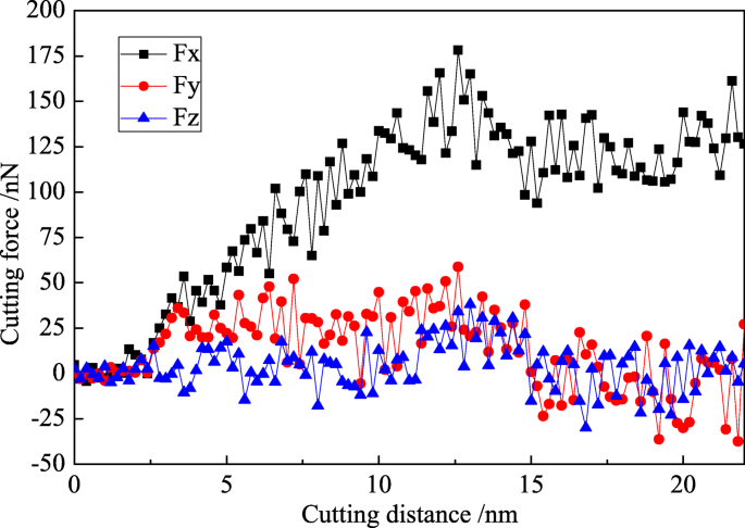
水介质纳米切削中切削力变化曲线
切削过程分为初始切削阶段和稳定切削阶段,如图 7 所示。在初始切削阶段,进给力和后退力呈直线急剧增加。当刀具完全切入工件时,它们达到最大值。在稳定切削阶段,切削力在其平衡位置上下波动,进给力达到200 nN以上,平均切削力约为180 nN。反力很小,在稳定切削后期逐渐减小。烘烤力的最大值在100 nN以下,平均值在50 nN左右。 Generally speaking, the specific value between average back force and average feed force (Fy/Fx) represents the friction coefficient between tool material and workpiece material in machining process. In this research, the friction coefficient between diamond and monocrystal copper is 0.278 under vacuum environment.
The feed force and the back force are decreased in nano-cutting with water media compared with vacuum environment, as shown in Fig. 8. The maximum feed force reaches 150 nN, and the mean feed force fluctuates at 120 nN. The variation tendency of back force is similar with the back force in vacuum environment, and the mean force is at about 25 nN. In nano-cutting process with the use of water medium, the friction coefficient between the cutting tool and the workpiece is reduced due to the lubrication of water. And then the frictional resistance suffered by the flank surface of cutting tool is reduced, which effectively enhances the extrusion shearing action of the rake surface of cutting tool. The removal of the workpiece material is easier to be removed. Hence, the cutting force is reduced. It can be seen from the foregoing analysis that the water molecules acted as a lubricant to prevent the friction between the cutting tool and the workpiece. Therefore, the values of feed force and back force are reduced in the water media. The specific value between the feed force and the back force is 0.208. In another words, the frictional coefficient between diamond and copper in water media is 0.208, much fewer than they are in vacuum environment (0.278).
Compared with the fluctuation of the Fy in Figs. 7 and 8, it is indicated that the Fy component decreases considerably after 15 nm of cutting distance in both cases with vacuum and water media while the Fx value is almost stable until 20 nm of cutting distance. The dynamic balance between dislocation nucleation and annihilation is achieved, and the chip is removed steadily in nano-cutting process, which results in the cutting force almost stable with the cutting distance before 20 nm. When the cutting process is carried out at a certain distance (15 nm in this research), the dynamic equilibrium between the new dislocation nucleation and the previous dislocation annihilation is established. And the scale of the internal defects of the workpiece is stabilized at a certain level. The dislocation nucleation and annihilation applied an effect on cutting tool along +Y direction, which leads to the Fy component decrease. Besides, the stable cutting chip is removed after 15 nm of cutting distance, and the applied force on the cutting tool from the chip is decreased along the Y direction. Thereby, the value of Fy is reduced. However, when the cutting distance is greater than 15 nm till 20 nm, the emotion of dislocation defect and the removal of chip cannot bring a different influence on the cutting tool along the X direction. Therefore, the value of main cutting force (Fx) is almost stable.
The temperature distribution of the workpiece during the nano-cutting process with and without the use of aqueous media is shown as Fig. 9. The cutting distances of Figs. 9a and b and Figs. 9c and d are 5 nm and 12 nm, respectively. It can be seen from Figs. 9b and d that the temperature of workpiece is distributed as a concentric gradient. The highest temperature is spread all over shear-slip zone and friction zone of the workpiece in a vacuum environment, which is above 420 K. The temperature of the chip and machined surface is higher than other regions, which is ranged from 360 to 390 K. For the whole workpiece, the temperature is at a high level, which is ranged from 340 to 360 K. From Figs. 9a and c, the temperature of the workpiece is also distributed as a concentric gradient and the highest temperature is distributed at the top area of the chip, which is around 370 K. The temperature value of the whole workpiece is at a lower level which is lower than 320 K. The temperature of the shear-slip area, the friction zone, and the machined surface are higher than other areas, which is ranged from 320 to 340 K.

Temperature distribution of workpiece in nano-cutting. 一 和 c are in water media, b 和 d are in vacuum environment
The highest temperature area of workpiece is transferred from the friction area to the cutting chip during nano-cutting process with water media as shown in Fig 9. And the highest and whole temperature of the workpiece are significantly reduced with the additional use of water media, and the temperature drop reached about 40–60 K. Due to the lubrication effect of water molecules, the friction between cutting tool and machined surface is reduced during nano-cutting process with water media. Hence, the temperature of the friction area declined dramatically. Meanwhile, the maximum shearing deformation occurred at the chip area and the maximum lattice deformation energy is stored in the chip, which makes the temperature of the chip higher than the friction area. Therefore, the highest temperature area is transferred from friction area to the cutting chip. Synchronously, a large amount of cutting heat is taken away by the water media which play a role in cooling the tool, workpiece, and cutting area. And the thermal movement of the monocrystal copper molecules is weakened. Furthermore, the kinetic energy of atomic thermal motion and the lattice deformation energy are decreased significantly. Therefore, the overall temperature and the highest temperature of the workpiece is reduced, whose degree of reduction arrived at 40–60 K. Finally, the thermal stress and thermal deformation of the workpiece are significantly reduced. Because of the participation of water media, the friction action between the flank surface of cutting tool and workpiece is weakened in cutting process. Then, the generation of heat by friction between cutting tool and workpiece is reduced. Thereby, the highest temperature area of the workpiece is transferred from the friction area of flank surface to the chip area. More importantly, the cooling effect and lubrication of water media will affect the nucleation, expansion, and annihilation of the dislocation in subsurface of the workpiece and ultimately affect the formation and evolution of the subsurface damage layers of the workpiece.
Effect of Aqueous Media on Subsurface Defects Structural Transformation
In order to clearly identify the subsurface defects of the workpiece in nano-cutting, the CNA method is used to analyze the workpiece after nano-cutting. The workpiece is colored by different atomic structure. The defect structural distribution of the workpiece during nano-cutting process with and without the use of aqueous media is shown as Figs. 10 and 11, in which the green, red, blue, and grey are FCC, HCP, BCC, and unknown structure, respectively.

Subsurface defect evolution of workpiece in nano-cutting without aqueous media. The green, red, blue, and grey area are representative of FCC, HCP, BCC, and unknown structure. The cutting distances of a, b, c, and d are 1 nm, 3 nm, 8 nm, and 15 nm, respectively

Surface and subsurface defect distribution in nano-cutting for workpiece with water media. The green, red, blue, and grey area are representative of FCC, HCP, BCC, and unknown structure. The cutting distances of a, b, c, d, e, and f are 3 nm, 8 nm, 12 nm, 15 nm, 18nm, and 20nm respectively
In nano-cutting process under vacuum environment, dislocation nucleation occurred at the subsurface of workpiece under the extrusion and shearing action of the cutting tool, and the crystal structure is transformed into BCC, which is shown as Fig. 10a. The nucleated dislocation is extended along \( \left[\overline{1}\overline{1}0\right] \) direction, and the crystal structure is transformed into HCP. The crystal structure of many atoms in the shear-slip region become BCC, as shown in Fig. 10b. Two partial dislocations are extended along the \( \left[\overline{1}\overline{1}0\right] \) and \( \left[1\overline{1}0\right] \) directions, hindered each other, and be composed of Lomer-Cottrell dislocation lock. Finally, a typical V-shaped dislocation loop is formed, as shown in Fig. 10c. Part of the atoms in the shear-slip zone are moved upward along the rake face and are removed as cutting chip. The other part of the atoms are migrated downward along the flank face and are formed into the roughness machined surface by the extrusion and friction of the cutting tool, as shown in Fig. 10d.
The subsurface defect distribution and evolution of workpiece in nano-cutting with the use of water media is shown as Fig. 11. It can be seen from the figure that the mechanisms of dislocation nucleation and crystal structure transformation are similar with the cutting process in vacuum environment. The main difference is that the dislocation nucleation and expansion is insufficient in the nano-cutting process of water media. Besides, there are many stacking faults nucleated in the subsurface of the workpiece. The structure of stacking faults is transformed into HCP structure. Nevertheless, a typical defect “similar-to-grain boundary (SGB)” is formed in the subsurface of the workpiece.
In nano-cutting process, under the action of extrusion, shearing and friction by cutting tool, intense deformation of the workpiece is generated. Plenty of deformation energy and cutting heat are produced. The atomic lattice reconfiguration of subsurface is produced by the release of cutting heat and strain energy. And the subsurface defects and local crystal structure transformation are formed, as shown in Fig. 11a and 11b. When the water media participated in the nano-cutting process, most of the heat and energy is taken away. Hence, the dislocation defects have inadequate energy to extension and movement. Furthermore, the stacking faults are annihilated in the subsurface of the workpiece where the crystal defect structure stayed behind, as shown in Fig. 11c, whereafter these crystal defect structures are connected as a whole and are composed of the subsurface damage (SSD) layer together with the newly formed dislocations, as shown in Fig. 11d. After the following MD relaxation, some subsurface dislocation defects are disappeared and transformed into FCC structure, and the structure similar to “grain” is formed between machined surface and subsurface defects layer, as shown in Fig. 11e, while the original subsurface defects are transformed into a typical structure “similar-to-grain boundary (SGB),” as shown in Fig. 11f. On the SGB structure, a typical V shape dislocation loop is formed, as shown in Fig. 11e, f.
The metamorphic layer is obviously formed by the influence of the formation of SGB and “grain” structure in the subsurface of workpiece. Moreover, the new formed crystal structures which are similar with polycrystalline material can influence the mechanical performance and processability of single-crystal materials. Besides, it will affect even the performance of machined nano-components.
结论
Based on the established MD models of single-crystal copper with and without the use of aqueous media, the simulation of nano-cutting process is carried out. The effects of fluid media on material removal and subsurface defect evolution are analyzed. The subsurface defect evolution, variation of the cutting force, the temperature distribution, and the subsurface defects crystal structure transformation of the workpiece are investigated by using CSP, DXA, and CNA methods. The novel results can be summarized as follows.
(1) The material removal of workpiece is realized by the shearing extrusion action of cutting tool on workpiece; the participation of water media has no effect on the mechanism of materials removal. Due to the lubrication action of water molecules existing between the cutting tool and the workpiece, the deformation of workpiece is decreased, the cutting force is reduced, and the height of cutting chip and depth of subsurface damage layer are lowered.
(2) The highest temperature area is transferred from the friction area to the cutting chip during nano-cutting process with the additional use of water media. And the highest and whole temperature of the workpiece are significantly reduced, and the temperature drop reached about 40–60 K. Thereby, the thermal deformation of the workpiece is reduced and the amount of subsurface defect atoms is decreased.
(3) In the subsurface layer of the workpiece, the crystal structures of nucleated dislocations are transformed into BCC, and the extended dislocations are transformed into HCP. The atomic crystal structures in the shear-slip region are becoming BCC. Under the effect of fluid media, the subsurface defects are transformed into a typical defect structure “similar-to-grain boundary (SGB)” in SSD layer, which can influence the mechanical performance and processability of single-crystal materials. Besides, it will affect even the performance of the machined nano-components.
缩写
- MD:
-
分子动力学
- CSP:
-
Centro-symmetry parameter
- CNA:
-
Common neighbor analysis
- DXA:
-
Dislocation extract algorithm
- PBC:
-
Periodic boundary condition
- EAM:
-
嵌入原子法
- L-J:
-
Lennard-Jones
- FCC:
-
Face center cubic
- HCP:
-
Close-packed hexagonal
- BCC:
-
Body centered cubic
- ICO:
-
Icosohedral
- SGB:
-
Similar-to-grain boundary
- SSD:
-
Subsurface damage
纳米材料