

碱性氧气炉炼钢化学
碱性氧气炼钢化学
碱性氧气炼钢 (BOS) 是使用最广泛的初级炼钢工艺,用于从铁水 (HM) 生产粗钢。工艺容器被称为转换器。它在生产粗钢的综合钢厂中发挥着主导作用。该过程包括在顶部喷枪的帮助下通过 HM 吹入氧气 (O2),以通过氧化降低其碳 (C) 含量。目前在1970年代后期发展起来的BOS工艺采用混吹。在混合吹气中,通过顶吹转炉的底部进行有限的中性气体、氩气 (Ar) 或氮气 (N2) 吹气。它提供了有效的搅拌。
BOS工艺有两个特点。首先,该过程是自生的,这意味着不需要外部热源。吹氧期间的氧化反应提供了熔化焊剂和废钢所需的能量,并达到钢水的所需温度。其次,该工艺以高生产率精炼 HM,以生产液态钢。快速反应速率是由于可用于反应的大表面积。将 O2 注入金属浴中时会产生大量气体。这种气体与通过 O2 射流的冲击从熔池表面剪切的液态熔渣和金属液滴形成乳液。气体-金属渣乳状液产生的大表面积提高了精炼反应的速率。
由于杂质溶解在熔融金属中,杂质和O2之间的反应与溶解的O2发生反应。此外,由于 C 的氧化发生在较高温度下,C 氧化成一氧化碳 (CO) 的可能性很高,因此大部分 C 以 CO 的形式被去除。
在BOS工艺中,通过氧化去除HM中的C、硅(Si)、锰(Mn)、磷(P)等杂质,用于生产钢水。用吹入转炉的高纯度 O2 气体进行氧化。氧化反应导致形成 CO、CO2(二氧化碳)、二氧化硅 (SiO2)、氧化锰 (MnO) 和氧化铁 (FeO)。当 CO 和 CO2 以气态形式从转炉顶部作为转炉气体排出时,其他氧化物会随着添加到转炉中的助熔剂而溶解,形成液态熔渣。液态炉渣能够从液态金属中去除 P 和 S(硫)。
BOS 过程中发生的反应可分为五类。第一类“金属吸收氧气”的反应是 (i) O2(g) =2O, (ii) (FeO) =Fe + O, (iii) (Fe2O3) =2(FeO) + O, (iv) CO2(g) =CO(g) + O。第二类“金属中元素的氧化”反应是 (i) C + O =CO(g), (ii) Fe + O =(FeO)、(iii) Si + 2O =(SiO2)、(iv) Mn + O =(MnO) 和 (v) 2P + 5O =(P2O5)。第三类“炉渣中化合物的氧化”反应为 (i) 2(FeO) + 1/2O2(g) =(Fe2O3) 和 (ii) 2(FeO) + CO2(g) =(Fe2O3) + CO。第四类“助熔剂反应”中的反应是 (i) MgO(s) =(MgO),和 (ii) CaO(s) =(CaO)。第五类“气体反应”中的反应是CO(g) + ½O2(g) =CO2。
BOS 是一个非常高动力学的过程,反应发生在多个位置。喷射液体相互作用和产生气态产物的 C-O 反应对整个过程动力学产生巨大影响。该工艺的特点是反应速率高,精炼过程通常在 12 分钟 (min) 至 15 分钟内完成。为了在这么短的时间内控制质量和生产力的过程,很好地理解过程的动态是很重要的。
典型的 BOS 转化器由一个底部为圆形的圆柱形筒体和一个用于将气体引导至排气罩的锥形顶部(25 度至 30 度半锥角)组成。主体支撑在称为耳轴的枢轴上,以便炉子可以旋转以进行装料、取样、出钢和除渣。内部通常衬有不同质量和厚度的镁碳耐火材料,以匹配磨损模式。转炉内部提供的典型体积约为每生产一吨钢水 1 立方米 (cum)。如果渣重为100公斤/吨(kg/t)至120公斤/吨,非活性熔池上方的干舷超过80%。这适应了在典型打击的中间部分发生的剧烈反应。转炉底部装有几个(通常为 6 到 8 个)多孔元件,Ar 气通过这些多孔元件进行熔池混合并帮助熔渣-金属反应。锥体下部一侧设有出钢口,用于出钢液。渣从嘴里倒在另一边。
BOS 过程是一个极快的精炼过程,需要良好的动态控制和动态模型以更好地理解该过程。该工艺的特点是在多个尺度上进行反应,例如在金属浴和熔渣的尺度上以及在液滴和气泡的尺度上。反应也在多个反应位点发生。超音速射流的存在与金属浴和渣层相互作用,在乳液中产生不同大小的液滴,在反应时在其界面产生大量气泡,石灰溶解问题等,描述了该过程的动力学复杂。
主要原材料是 1,300 摄氏度至 1,400 摄氏度左右的 HM。由于产生的热量超过了所需的热量,因此使用废钢和铁矿石作为冷却剂。一些炼钢车间添加石灰石 (CaCO3) 作为冷却剂以调节最终温度。煅烧石灰 (CaO) 用作助熔剂,以实现去除 P 所需的高碱度。首先将废钢添加到空转炉中(在从先前的加热炉中出渣之后),然后在其上添加所需数量的 HM。使用时,铁矿石通常在吹炼的前半段以分布式方式添加。
在添加废料之前添加部分或全部所需的石灰,以作为保护衬里免受废料掉落的冲击垫。其余的石灰通常在吹炼过程中以分布式方式添加。一些氧化镁 (MgO) 以煅烧白云石 (CaO.MgO) 的形式添加,以尽量减少耐火材料溶解到熔渣中。考虑输入成分、HM温度、输出钢成分和温度,通过基于材料和热平衡的炉料控制模型理论计算不同炉料的数量。
精炼反应都是氧化的。这是通过配备 3 至 6 个超音速流喷嘴(2.0 马赫至 2.1 马赫,与喷枪轴线成一定角度安装)的顶部喷枪吹入吨位氧气来实现的。喷枪的尖端保持在大型转炉中静金属浴液面上方 1.8 米 (m) 至 2.5 m 的距离处。喷枪高度是控制工艺的操作参数之一
典型的点击到点击循环由此处描述的步骤组成。装料顺序是石灰、废料和 HM。一旦转炉竖立起来,氧气枪就会降低到所需的高度(最初,最高值,2.2 m 到 2.5 m)并开始吹气。在吹制的前半部分,如果有的话,还要添加额外的石灰以及铁矿石、煅烧白云石和任何其他添加剂。在吹炼的后半部分避免添加含水材料,以保持所生产钢中的氢 (H2) 较低。继续进行高喷枪操作(通常为 3 分钟至 4 分钟),直到炉渣中含有足够的 FeO 以促进石灰溶解。此后,喷枪逐渐降低以达到所需的精炼速度。喷枪高度根据个别工厂的实际情况分3步降低到5步。
在大约 80% 到 90% 的吹气(基于 O2 流量)时,取样进行分析并测量温度,以便在完成吹气时,同时达到所需的成分和温度。采样和温度测量可以手动完成,即停止吹气,将转炉转至接近水平位置并通过勺子取样并测量温度,或者通过降低到吹气转炉中的副枪(在-吹样)。根据样品分析和温度,吹气的剩余部分通过必要的装饰添加完成。吹炼完成后转炉转向出钢侧倾倒钢水,然后转向另一侧出渣。在现代实践中,保留一些炉渣,将转炉竖立起来,加入一些菱镁矿(MgO),然后通过吹入高速N2将炉渣溅到内表面上。定期手动或通过激光扫描仪检查空转炉是否有耐火材料损坏。通过喷射耐火喷射质量来修复损坏。在此之后,转换器已准备好进行下一次打击。
BOS 过程是一个在短时间内发生的复杂过程,随着过程的进行,几乎没有可用的直接反馈信息。该过程由几个子过程组成,这些子过程要么不被理解,要么只是半定量的理解。由于该过程是一个自生过程,即使在输入 HM 在 1,350 摄氏度左右并且输出钢在 1,650 摄氏度到 1,700 摄氏度出钢之后,仍然存在热量过剩。因此,使用了不同的冷却剂,废钢和铁矿石作为主要的。氧气通过超音速射流进入热和含尘气体或液态气体乳液中,射流行为受到周围环境的影响。图1为BOS流程示意图,其基本特点如下。
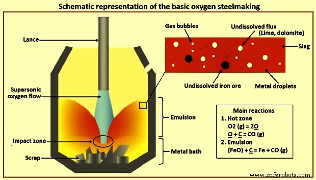
图1氧气基本炼钢示意图
碳氧化 – 镀液中 C 的脱碳是 BOS 工艺中最广泛和最重要的反应。在该脱碳反应过程中有三个不同的阶段。在吹炼的最初几分钟内发生的第一阶段,脱碳以缓慢的速度发生,因为大部分供应的 O2 与浴中的 Si 反应。在第二阶段,发生在镀液中高 C 含量的情况下,脱碳以较高的速率发生,并由供应 O2 的速率控制。第三阶段发生在镀液的 C 含量达到约 0.3% 时。在这个阶段,脱碳率下降,因为较少的 C 可用于与所有供应的 O2 反应。在这个阶段,速率由 C 的传质控制,O2 主要与铁 (Fe) 反应形成 FeO。在这个阶段,由于CO的生成率下降,转炉口的火焰变得不那么明亮,当C下降到0.1%左右时,火焰几乎消失了。
硅氧化 – 有利于硅氧化的条件是 (i) 低温,和 (ii) 炉渣中的 SiO2 含量低。碱性炉渣有利于硅氧化。在碱性渣中,Si 氧化实际上发生在非常低的值,因为 SiO2 与 CaO 反应并降低渣中 SiO2 的活性。由于 O2 对 Si 有很强的亲和力,几乎所有的 Si 都会在吹炼的早期被氧化和去除。 HM 的 Si 在冲击的前 3 分钟到 5 分钟内被氧化到非常低的水平(小于 0.005 %)。 Si 氧化成 SiO2 是放热的,它会产生大量的热量,从而提高浴温。它还形成硅酸盐渣,与添加的石灰和煅烧白云石反应形成碱性渣。由于 Si 的氧化是主要热源,其在 HM 中的数量决定了可以添加到转炉中的冷料(废钢和生铁等)的数量。它还决定了炉渣的体积,从而影响镀液的脱磷和收率。根据经验法则,渣量越高,P越低,产率越低。
铁氧化 – 铁 (Fe) 的氧化对于 BOS 工艺来说是最重要的,因为它控制 (i) 渣中的 FeO 含量和钢中的 O2 含量,(ii) 渣中 Fe 的损失,从而影响炼钢的生产率(iii) 渣的氧化电位, (iv) FeO 有助于 CaO 在渣中的溶解。
锰氧化 – BOS 工艺中的锰氧化反应相当复杂。在顶吹转炉中,Mn 在吹炼的早期阶段被氧化成 MnO 氧化物,在大部分 Si 被氧化之后,Mn 又回到熔池金属中。最后,在吹炼结束时,当更多的 O2 可用于氧化时,熔池金属中的 Mn 被还原。在转炉底吹或复吹情况下,Mn的氧化具有相似的规律,但转炉钢液中残留Mn含量高于顶吹转炉。
磷氧化 – 转炉中的氧化条件有利于镀液金属的脱磷。脱磷反应是由于镀液中金属和熔渣的相互作用而发生的。较低的浴温、较高的渣碱度(CaO/SiO2比)、较高的渣中FeO含量、较高的渣流动性以及良好的浴搅拌等参数有利于脱磷反应。熔池金属的磷含量在吹炼开始时减少,然后在主要脱碳阶段,当 FeO 被还原时,P 恢复到熔池金属中,最后在熔炼结束时再次减少。浴搅拌改善了金属和炉渣的混合,有助于提高脱磷速度。加入面粉晶石等助熔剂进行良好的搅拌,还可以通过增加CaO的溶解来提高P的去除率,从而形成高碱性和流动性的液态渣。
硫反应 – 由于高度氧化的条件,在 BOS 工艺中脱硫效果不是很好。在二次炼钢过程中,S 分配比(渣中的 % S / 金属中的 % S)约为 4 至 8,远低于钢包中的(约 300 至 500)。在 BOS 过程中,浴中约 10% 至 20% 的 S 与 O2 直接反应形成 SO2(二氧化硫)。剩余的 S 通过炉渣 - 金属反应 S + CaO =CaS + FeO 去除。渣的高碱度和低铁含量有助于渣去除 S。钢水的S含量受HM中的S和转炉中加入的废钢的影响很大。
在 BOS 过程中发生的反应是异质的并且在不同的长度尺度上。有本体金属浴相、本体熔渣相和气相。另一方面,大部分反应发生在分布在熔渣/金属/气相乳液相中的细小液滴和气泡的规模上。长度尺度的不同也会导致时间尺度的不同。金属浴在 12 分钟到 15 分钟的整个热循环中会发生变化,而液滴可以在大约一分钟内经历完整的精炼循环。因此,基于商业和中试工厂的观察和测量、精心设计的实验和数学建模,过程动力学的图景已经发展了几年。
HM 的典型成分可以是 C – 4.5 %、Si – 0.3 % 到 0.5 %、Mn – 0.2 % 到 0.7 %、P – 0.1 % 到 0.18 %、S – 0.02 % 到 0.03 %,温度为 1,350 摄氏度. 由于 S 只能在铁液存在的情况下以还原态脱除到渣中,因此碱性氧气炼钢中的氧化过程并没有去除任何相当数量的 S。有意义的整体反应可写为 (i) [Si] + {O2} =(SiO2), (ii) [Mn] + 1/2 {O2} =(MnO), (iii) [C] + 1/2 {O2} ={CO}, (iv ) 2[P] + 5/2 {O2} =(P2O5), (v) Fe (l) + 1/2 O2(g) =(FeO)。 [-]、{-} 和 (-) 分别用于溶解在金属浴中的准金属、气体和熔渣中的成分。图 2a 给出了 200 吨转炉中的反应进程。在不同转换器中进行的测量也显示出类似的模式。图2b给出了炉渣成分的相应演变。
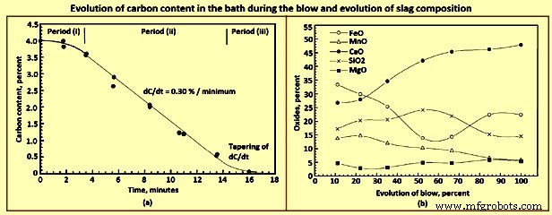
图2 吹炼过程中熔池中碳含量的演变和熔渣成分的演变
金属成分演变的一个显着特征是,即使在 Si 下降到非常低的水平之前,也会同时去除大量 C。观察到 CO 火焰在吹氧开始后的短时间内在转炉口喷出也证实了这一点。这与现在过时的 Bessemer 转炉或 OBM 工艺中的观察结果形成对比,其中空气 / O2 从底部吹出。在这两个过程中,显着火焰的出现需要一些时间,这被认为表明直到 Si 下降到相当低的值才开始 C 氧化。
在热力学上,对于上述输入条件,任何局部位置的溶质氧化反应的顺序是 Si、Mn、C 和 P。也就是说,在吹气初始部分的主要条件下,Si 在之前被氧化C.较低的初始温度本身使Si反应有利。此外,产品 SiO2 在从一开始就保持的高碱性条件下具有非常低的活性。另一方面,CO 分压几乎保持在 0.1 MPa(一个大气压)。例如,如果假定 SiO2 的活度为 0.001,则与 4.5% C 和 0.5% Si 平衡的 pO2 分别为 1MPa 至 1.7 MPa 和 1 MPa 至 1.9 MPa。这一特点使得对过程动力学和反应机理的分析变得有趣。
工艺特点
由于来自过程的反馈信息是有限的,因此有必要根据从可以获得的信息中观察到的特征来建立过程动力学模型。 BOS流程的重要特点如下所述。
反应速度非常快。在脱碳高峰期,C 以每分钟 0.3% 左右的速度被去除,也就是说,在 200 吨转炉中每分钟可以去除大约 600 公斤的碳(图 2a)。 C反应显示了三个典型时期(图2a),即(i)速率增加的初始时期,(ii)尽管浴中的C含量连续不断,但速率相对恒定的中间时期在此期间,从大约 3.5% 下降到 4.0%,最后第三个时期超过临界 C 含量,当速率逐渐减小时。临界C含量一般在0.2%~0.5%之间。
然而,具有相同吹塑条件的各个炉次显示出广泛的不可再现性。具有相同输入和工艺参数的两次连续吹炼会表现出完全不同的行为,其中一些吹炼会出现喷溅(金属-渣-气乳液在转炉口沸腾)或干渣和喷溅(导致喷枪和吹口堆积) .在 BOS 工艺的早期阶段,这种不可再现性更为普遍,当时还没有加入底吹搅拌气体。使用较少的废料作为冷却剂还可以提高再现性并减少喷溅。
在对几家 BOS 车间进行研究后,发现峰值脱碳率与吹氧率成正比。在实验室转炉的吹炼过程中也表明,增加 O2 吹扫速度和降低喷枪高度对峰值脱碳率的影响是相似的。
在 MEFOS(瑞典的一家研究机构)的试验转炉中进行的实验表明,沿顶吹转炉的高度存在浓度变化。这表明尽管顶部射流有巨大的动量,但顶部吹气不能很好地混合金属浴。但是,从底部吹入极少量的惰性气体后,这种差异就消失了。
众所周知,BOS 工艺中的渣在渣相中含有相当一部分以液滴形式存在的金属。数量在打击期间变化,在打击的中间部分最高。估计值在 10% 到 25% 的范围内变化。这些液滴非常细,大多数小于 1 毫米至 2 毫米。乳液中的液滴数量在吹气结束时下降。与大块金属浴相比,液滴通常处于更高级的精炼状态。
在大部分吹炼过程中存在渣-金属-气乳状液。通过大约三分之一的打击,乳状液高度超过大约 2 m,因此淹没了喷枪尖端并静音了超音速射流的声音。有时,乳液会填满整个炉子,在嘴巴上沸腾(溢出)。在熔池中超过临界 C 的吹炼快结束时,乳液塌陷,表明乳液是暂时的,需要连续产生气体才能生存。
如前所述,C、Mn 和 P 在吹炼的初始部分与 Si 同时被氧化,与基于块状金属浴成分的其他反应相比,Si 反应优于其他反应的预期。 Mn 和 P 的反应在一定程度上可以通过炉渣中的活动来解释。 C反应无法解释,除非人们假设在反应部位不占主体金属成分。
在吹炼的中段,Mn 和 P 发生逆转(图 3a)。这也反映在渣路径中(图 2b)。然而,很明显,还原与炉渣中的 FeO 含量相关。尽管在吹炼开始或早期添加石灰,CaO 的溶解几乎一直持续到结束。 C 决定了过程的整体动态,并且该反应剧烈地发生。图3a显示了吹炼过程中熔体成分的变化。
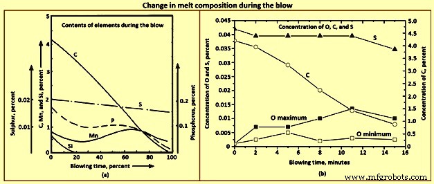
图 3 吹塑过程中熔体成分的变化
BOS 过程的动力学取决于剧烈发生的 C 反应。完整的动态可以分为几个站点。在这个框架上可以理解其他反应。 O2 射流几乎是纯净的,分子直接到达浴槽表面,没有相当大的传质屏障。当一个分子撞击时,它可以做以下事情之一。
O2 分子在撞击点与 C 发生反应。反应可以是 [C] + 1/2{O2} ={CO},并且 [C] + {O2} ={CO2}。它可以以[O]的形式溶解在金属中。然后它可以传播到其他地方并与其他可氧化元素如 O2 =2[O] 发生反应。根据方程式 Fe + 1/2{O2} =(FeO),其中一些可以与浴中的 Fe 反应生成 FeO。 FeO 可以进入渣相并与其他地方的金属发生反应。这些中的每一个都会导致精炼反应在转炉中不同的可能位置发生,从而在混合时导致整体浴精炼。这些不同的站点如图4所示。
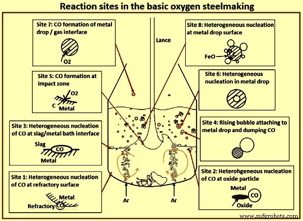
图4氧气碱性炼钢反应位点
请记住,C-O 反应是多相的。至少有一个可以限制速率的传质步骤。 C必须在金属中扩散到界面。根据反应的 O2 源,也可能涉及气相中 O2、金属相中溶解 O2 或渣相中 FeO 的转移。溶解的 O2 可以移动到金属浴内的其他部分,并与溶解的 C 反应,将 CO 释放到耐火材料中的充气孔中(位置 1)。 CO 也可以通过异相成核(位点 2)在漂浮在金属浴中的固体颗粒上形成。非均匀成核也可以发生在渣层/金属浴界面(位置 3)。除非 CO 过饱和度非常高,否则浴中的均匀成核是极不可能的。如前所述,CO 反应可以直接在撞击地点(地点 5)发生。在冲击部位或附近形成的一些 FeO 可以进入金属浴表面并沿着熔渣/金属界面移动,与 C 反应形成乳化界面(如部位 3)。然而,大部分形成的FeO可能转移到渣相。
这现在提供了几种可能性。在熔渣和金属浴之间的界面处,可以发生如前所述的反应(位置 3),现在 O2 来自熔渣相,C 来自金属。如前所述,渣相包含大量金属液滴,由冲击部位的射流动量不断产生。因此,炉渣中的 FeO 可以通过不同的机制与这些液滴发生反应,例如 (i) CO 气泡可以在界面(位点 8)处异相成核,(ii) CO 可以转移到与液滴(位点 4),和 (iii) 如果超饱和度非常高(位点 6),CO 气泡可以在液滴内均匀成核。如果一些金属液滴被抛到自由板上,它可以直接与气体中的任何 O2 或 CO2 发生反应(站点 7)。
尽管所有这些站点在一定程度上都可以在打击期间处于活跃状态,但仍需要确定决定整体动态的主要机制。可以根据观察来评估每个站点的贡献。事实上,在没有底部气体注入的情况下,熔池显示出浓度梯度,与顶部气流相比,只有 1% 的惰性气体从底部吹出,该浓度梯度就消失了,位置 1 和位置 2 的机制可以被认为是不重要的。
预计撞击区表面的温度将高于 2,120 摄氏度。因此,预计化学反应的速率会非常高。撞击点面积比较小,O2 到达率很高。然而,溶质需要扩散到界面并且热量必须传导到金属中。新鲜金属被带到被大表面速度向外扫掠的界面。在这些情况下,可以预期撞击表面缺少溶质,留下一层与 O2 反应的 Fe。最终可以合理地假设体金属组合物的一层金属被完全氧化,凝聚相氧化物被转移到渣层。当 C 含量约为 5 %(20 至 25 mol %)时,该近似值意味着在该站点消耗了大约 25 % 的供应 O2 用于 C(CO 和 CO2)。根据假设金属侧传质不是速率控制的计算,估计贡献约为 40%。曾经,它被认为是主要机制(热区或冲击区理论)。如前所述,在该位置向外流动的金属层也会被O2饱和。
乳液中的反应似乎包含主要的反应位点(位点 4、6 和 8)。乳液中的液滴具有极大的比表面积。在渣中存在合理数量的 FeO 的情况下,液滴中的所有精炼反应可以在几十秒内完成,而不是几分钟。含有 4.5% C 的 3 毫米金属滴可以释放出大约 3,000 倍其体积的 CO。当它通过粘性熔渣逸出时,会使其乳化。因此,乳液形成、液滴生成、液滴停留时间等复杂的相互作用对整体动力学有很大贡献。液滴与气相直接反应的反应主要在喷吹的最初几分钟内很重要,此时尚未形成完整的渣层。
全面了解这一整体过程动力学需要了解超音速气体射流、它们与金属/熔渣浴的相互作用、液滴生成及其停留时间、CaO 溶解和浴混合等方面的背景。
气体中的气体射流在其外围夹带环境气体。扰动层在下游几个喷嘴直径处(潜在的核心区域)到达射流轴,在此之后,流动变得完全发展,具有自相似的径向速度分布。轴向速度与距离成反比以保持动量守恒。通常,如果环境气体具有与喷射气体相同的密度,则喷射以大约 10 度到 12 度的半锥角膨胀。如果环境较轻,由于质量效应,膨胀较小。
在超音速喷气机中,压缩系数影响喷气机的膨胀。已经表明,在轴向速度减速到音速(超音速核心)之前,射流不会膨胀太多。此后射流膨胀为亚音速射流,如图 5 所示。最近对 O2 射流进入 BOS 转换器的 CFD(计算流体动力学)研究表明,轴向速度在大约 1 m 的距离内几乎是恒定的,温度为轴上的气体在该区域保持在 -170 摄氏度左右。此后,由于热气体的夹带,温度稳步升高。因此,O2 喷枪在出口马赫数约为 2 的情况下运行,这样它就可以保持一定距离,并且仍然可以实现良好的射流/金属相互作用。
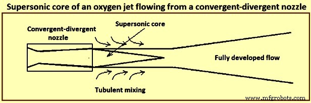
图 5 从收敛-发散喷嘴流出的氧气射流的超音速核心
可以看出,如果像BOS转炉那样将O2射流浸没在CO气氛中,O2的浓度可以大幅度下降。
当高速射流撞击金属表面时,会形成一个陨石坑,由于偏转射流的高速,陨石坑的边缘非常不稳定,会抛出金属液滴。在足够高的值下,射流会重新进入,其中一些液滴被抛入射流本身,导致高度不稳定的陨石坑摆动和旋转。在存在渣层的情况下,这些液滴会被渣捕获,形成渣中液滴乳状液。
The crater depth can be calculated by performing a momentum balance at the stagnation point at the centre of the crater. In further studies with a constant based on the experiments with various liquids and gases at room temperature and quantitatively studying the emulsification phenomena with the help of a 2-dimension, two phase model of mercury and glycerol, it has been found, as expected, that the droplets in the emulsion are increased with gas flow rate and varies inversely with stand-off distance of the lance tip from the liquid surface (lance height). While experimenting with a 3-dimension model of water to determine the droplet generation rate with a top layer representing slag, it has been found that there are two regions, one at a lower flow rate where the rate increases nonlinearly with flow rate and the second where the rate varies almost linearly with the flow rate. The Weber number has been used to characterize the flow phenomena. Droplet generation rate (kg/second) is correlated experimentally as a function of the blow number. It has been shown that simultaneous bottom gas injection can increase droplet generation especially when they are nearly coaxial with the top jet. The presence of slag phase can change the rate of generation substantially.
In a supersonic jet, say of Mach 2, the exit gas temperature is around -100 deg C. Thereafter, it entrains lower density converter gas. The temperature, velocity, and composition of the gas change as the jet strikes the bath. Hence this correlation has large uncertainties, because of which usefulness of the correlation in the BOS model is less than adequate. Since there is no other correlation, one normally uses the above correlation for generation of droplets and tunes it as needed.
The reaction rates also depend on the droplet sizes. Several studies have obtained emulsion samples from the working converters or laboratory hot models. These studies have found in general the sizes to be in the range of 0.05 mm to 3 mm. In a study experimenting with pig iron and O2, there were large chunks of liquids thrown out, which normally spend negligible quantity of time in the emulsion. Though these approximations and correlations are clearly inadequate, most models use these for lack of better correlations.
One of the studies found large quantities of metallic droplets in the foamy slag formed during high P iron refining. Another study made similar observations by collecting samples ejected through the tap hole in a 230 t converter and analyzing them. Several other studies have also made similar observation.
As mentioned earlier, the droplets are in various states of advanced refining, some of them being almost completely refined, though the bath still had considerable quantity of C. The fraction of metal in the emulsion has been estimated to be large, being almost 25 % of the bath weight. This corresponds to a surface area of around 40,000 square metres (sqm) if one assumes an average size of 1 mm for the droplets. It has been proposed in one of the studies that refining in the converter takes place primarily in the emulsion phase, the bath seeing refining by dilution from droplets falling back (emulsion theory). Emulsion in the converters refers to a slag-metal-gas system. One can visualize it as slag-gas foam in which metal droplets are distributed.
It has been also reported that several of the droplets display high O2 super-saturation and this has postulated that the finer droplets can have been generated by homogeneous nucleation of CO droplet bursting. Some droplets show evidences of being attached to gas bubbles and some are even hollow. There have been several experiments with magnetically levitated and freely falling droplets reacting with oxidizing gases. The results of these experiments are interesting. When the C content is high, one can see reactions taking place at the surface, as evidenced by CO burning. As the C content comes down, small droplets are thrown out indicating sub-surface nucleation. Further lower in C content, the droplets sometimes burst, indicating O2 super-saturation and nucleation deep within the droplet. Super-saturation to the extent of around 5 MPa (for equilibrium CO) had been reported at the time of droplet bursting.
In one of the studies, the residence time of the droplets in a converter has been measured by radioactive gold isotope tracer technique. The maximum residence time of droplets which are in advanced state of decarburization has been estimated to be around 2 minutes. Residence time calculated on the basis of free fall is of the order of a few seconds even while considering the slag to be emulsified to a much greater height. The high residence time hence needs an explanation.
Several experiments using X-rays for visualization of a single Fe-C droplet reacting in molten oxidizing slags have shown that the droplet gets buoyed up to the surface as soon as decarburization starts, and stays at the surface till the CO bubbling subsides. Further, it has been shown that the droplet residence time is dependent on bubble formation which keeps the droplet afloat.
There are two views on how the CO formation keeps the droplet buoyant. One of the studies has formulated a bloated droplet theory wherein CO forms homogeneously inside the droplet and this hollow droplet has a low apparent density, due to which it remains afloat. The other view is that the bubbles form heterogeneously at the droplet / slag interface and as long as the bubbles stay attached to the droplet they keep it afloat. The visual evidences from X-ray fluoroscopic studies cannot clearly distinguish between these two. The fact that there does not seem to be a nucleation barrier during vigorous deoxidation as evidenced by copious evolution of bubbles suggests interface nucleation.
At high C concentrations when C mass transfer within the drop is not rate controlling, the highest CO super-saturation is to be seen at the droplet surface. Hence, it can be expected that for the nucleation to take place heterogeneously at the surface, the bubble is to spend some time at the interface before detaching. Since there can be several bubbles attached, the droplet remains buoyed. As C falls to low values, nucleation at the interface becomes sporadic, and in periods when there is no bubble attached, O2 dissolves into the metal and diffuses in. Hence, the highest super-saturation region moves inward, first to sub-surface and then to deep inside the droplet. One can thus see sub-surface nucleation initially throwing out small droplets and then deep inside. These homogeneous nucleation events are probably sporadic, with a stochastic nature.
Simultaneously, the apparent density of the droplet with no or few bubbles is now high and it falls down into the metal bath. The critical C content when the droplet falls down depends on droplet size, the oxidizing potential of the slag (and the rate of mass transfer of FeO), and the sporadic nucleation event either at the surface or inside the droplet. Empirical work to correctly predict the critical C content is lacking. Evidence from levitated droplet experiments also point towards these series of events, though the stirring due to the electro-magnetic field makes the condition different from that in the converter especially with respect to mass transfer within the droplet.
In the context of converter, the droplet surface is continuously disturbed by the bubbles. This has two counteracting effects. Part of the droplet surface is covered by the gas bubble and is not available for mass transfer from the slag to the droplet. The droplet surface is also vigorously stirred by the formation and detachment of bubbles, enhancing mass transfer locally. Several indirect estimations have been made. In one of the studies, indirect estimation of mass transfer coefficient has been made for FeO in slag for P transfer rate in high temperature single droplet experiments, and the values obtained are between (10)−5 metres per second (m/s) and (10)−4 m/s . Another study estimated similar values. Proper experimental studies, both in cold and hot models, are necessary to get reasonable correlations in terms of dimensionless variables.
Though the slag is very well stirred in the converter due to the gas jet and a large quantity of gas passing through it, the metal bath in top blown converters is comparatively poorly mixed. Measurement of mixing time (t95 which is the time to get 95 % homogeneity) in top blown converter can be as high as 150 seconds (s) to 180 s, as compared with 10 s to 20 s in bottom blown OBM converters. This has consequence on the reaction dynamics, since the metal droplets are removed from the top layer and the refined droplets from the emulsion fall back at the top. Since much of the heat is also released in the slag, the slag and the droplets falling back are also hotter. There can also be composition and temperature stratification due to the scrap at the bottom slowly dissolving into the liquid metal.
High mixing times also correspond to high irreproducibility in mixing times, leading to irreproducible blow behaviour in the absence of bottom blowing. For example, a large eddy of liquid metal containing higher C from the bottom being brought to the surface of the metal bath can suddenly increase the rate of decarburization leading to instabilities. Hence, inert gas injection from the bottom of the converters to bring down the mixing time has become the standard practice.
Since the rate of bottom gas injection and the position of the porous elements through which the gas is introduced have a bearing on the reaction dynamics, it is necessary to quantify the mixing behaviour for quantitative predictions of composition and temperature evolution. A single average t95 value is inadequate for incorporation into a comprehensive model of the converter, since two different mixing curves can give the similar t90 (time to get 90 % homogeneity) and different t95 values. The compromise can hence be a two parameter model, based on estimation of two mixing times (t90 and t95). One can then idealize the metal bath as consisting of two stirred tank reactors (STR), exchanging metal continuously. The bottom part sees only scrap melting and the top part sees all other phenomena explained earlier. The two parameters of this model, ratio of reactor sizes and the metal exchange rate can then be fitted to the mixing times of the converter under various conditions of operation.
Formation of slag and dissolution of fluxes
Fluxes (lime and calcined dolomite) which are charged early in the blow dissolve with the developing oxides to form a liquid slag. The rate of dissolution of these fluxes strongly affects the slag-metal reactions occuring during the blow. At the beginning of the blow, the lance height above the bath is kept high which causes an initial slag rich in SiO2 and FeO. During this period large quantities of fluxes are charged in the converter. The lance is then lowered and the slag starts to foam at around one third of the blow due to the reduction of FeO in the slag in conjunction with CO formation. As the blow progresses, the CaO dissolves in the slag, and the active slag weight increases. After the blow has progressed around three fourth of the time, the FeO content in the slag increases because of a decrease in the rate of decarburization.
During the blow, the temperature of the liquid steel gradually increases from around 1,350 deg C to 1.650 deg C at turndown of the converter, and the slag temperature is around 50 deg C higher than that of the liquid steel. The slag at turndown can contain regions of undissolved lime mixed with the liquid slag, since the dissolution of lime is limited by the presence of dicalcium silicate (2CaO.SiO2) coating, which is solid at steelmaking temperatures and prevents rapid dissolution. The presence of MgO in the flux weakens this coating. Hence, earlier charging of MgO speeds up slag formation due to quicker solution of lime.
The converter needs to maintain a good fluid slag of high basicity (high CaO content) so that the large quantity of CO generated can be handled, and P can be removed efficiently. Hence, the converter operator tries to achieve a CaO / SiO2 ratio in excess of 3.0 in the final slag.
Fig 6a shows the liquidus contours in a CaO-SiO2-FeO ternary diagram. It is clearly seen that a CaO / SiO2 ratio which can be achieved in this system at 1,350 deg C, i.e. at the beginning of a blow this ratio is limited to around 1.6 to 1.7. Marginal improvement can take place with MgO additions (Fig 6b) and some Al2O3 coming from the carry over slag. In the final slag also at 1,650 deg C with 25 % to 30 % FeO, the maximum CaO / SiO2 remain less than 3.0. This is also borne out by the slag analyses which frequently show un-dissolved lime. Apart from the issue of solubility of CaO in the converter slags, the lime particles get passivated in the presence of highly siliceous slags. Since the CaO concentration is the highest at the surface of a dissolving lime particle, di-calcium silicate forms here. This compound is not only highly refractory but it forms an adherent layer retarding further dissolution.
A lime particle remaining undissolved for long at the high temperatures also sinters and becomes less reactive. One way of breaking the adherent layer is to have high FeO content in the slag. This is the reason for the practice of raised lance blowing in the first few minutes of the blow, when the FeO is built up to 25 % to 35 % or higher. Though the effect on solubility of CaO is marginal (Fig 6), this facilitates breaking of the adherent di-calcium silicate layer permitting further dissolution.
Additives like fluorspar (CaF2) can bring about this effect much more efficiently, though this is not an acceptable plant practice in recent times for various reasons. Fig 6 shows phase diagrams with Fig 6a showing liquidus isotherms of CaO-SiO2-FeO system and Fig 6b showing tffect of MgO addition on the liquidus.
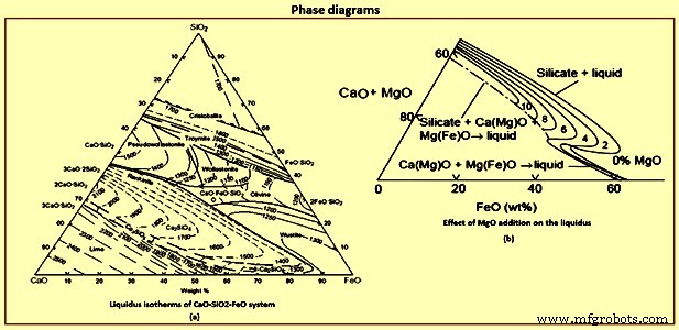
Fig 6 Phase diagrams
Process flow and reaction dynamics
The contents of the converter can be divided into several important regions such as (i) the metal bath, which itself can be divided into the bottom and top part between which there is exchange of metal, (ii) the O2 jet and the impact region, and (iii) the slag region which mostly is in the form of a slag-metal-gas emulsion. There are three distinct regimes in the blow. The initial part is characterized by a bare metal bath covered with islands of solid lime and some slag carried over from the previous heat. Jet of O2 hits the metal bath and does two primary things. First, it oxidizes almost an entire layer of the metal giving CO, SiO2, MnO, P2O5 and lots of FeO. Not all O2 is consumed in this location, and the gas above hence can contain high ratio of CO2 / CO and some O2 as seen in exhaust gas analysis. The jet also throws droplets into the gas phase, which after free flight fall back. Since the gas is oxidizing, the droplets get refined during the flight. At the surface of the droplets, the order of reactions is dictated by the thermodynamics.
For each of the solutes, reaction involves mass transfer steps such as mass transfer of CO2 / O2 in the gas phase and of the solutes in the liquid phase. The interfacial chemical reactions are expected to be very fast at this temperature. The order of the reactions can be achieved by solving the mass transfer equations along with free energy minimization for the interface reactions competing for O2. The order is normally Si and Mn followed by C and P. Since the time of flight is typically of the order of a second or lower, the droplets fall back probably completing only part of the Si reaction. Smaller the droplet, further the refining proceeds because of the larger specific surface area. Reaction at the rest of the surface of the metal bath is small because of the smaller surface area compared to that of the droplets.
The mass transfer in the gas phase can easily be calculated by Ranz-Marshall type correlations. At this initial phase of the process droplets are high in solutes, and the gas phase mass transfer is expected to be rate controlling. The small droplets can be considered as rigid and one can assume pure diffusion of solutes inside the droplets. When the droplets fall back, the condensed phase oxide products in the droplets remain at the top of the bath, and on combining with the oxides from the impact site and the fluxes added start forming a liquid slag. As mentioned earlier, good quantity of FeO is formed at the impact site, and hence liquid slag formation is easy. After sometime, there is a liquid slag layer covering the metal bath. Increasingly more and more droplets are thrown to the slag. The droplets ejected into the gas phase now have to pass through the slag phase before reaching the metal bath. Further refining hence takes place in the slag.
Initially when the slag layer is thin and the droplets are high enough in Si and Mn, the droplets fall through before the C reaction starts, that is, with no gas evolution, especially for larger droplets. Smaller droplets high in C can however start to decarburize early releasing CO, and slowly emulsifying the slag. This early phase is characterized by a low flame at the mouth, since CO formation is comparatively low. Once the Si in the metal bath falls down to some extent, the desiliconization progresses considerably, before the droplet has fallen down. C reaction starts and the droplet stays now buoyed in the emulsion till its C content reaches the critical C content as explained earlier. In the slag phase, the rate is expected to be controlled by slag phase mass transfer of FeO, as long as C in the droplet remains high enough. Once a critical C is reached in the droplet, bubbling slows down and then ceases, and the droplet falls down. The critical C is largely determined by the FeO content in the bath. Quickly the emulsion builds up and the second phase of reactions in the emulsion starts. The flame at the converter mouth becomes large. The lance tip gets dipped into the emulsion.
In the second phase almost all of the droplets are ejected into the emulsion, and the gas phase reactions become unimportant. It is to be noted that the residence times of the quiescent droplets in the slag are only of the order of a few seconds unless decarburization reaction starts. Hence, for maximizing the refining, the operator is to quickly reach a stage where the decarburization reaction starts before the droplets fall back. One way to accelerate the reactions is to keep the FeO content in the slag high. Another reason why FeO is to be increased as early as possible is to have a fluid slag by the time decarburization rate reaches its highest value, since the large quantity of gasses are to quickly escape from the slag. Else, the emulsion height gets build up uncontrollably leading to overflow, and slopping.
The FeO content in the slag is a balance between its generation at the point of impact and its consumption by the droplets in the emulsion. The FeO generation is probably weakly dependent of the lance height, whereas a high lance leads to less droplet generation due to lower force with which the jet strikes the metal bath, and vice versa. Hence a raised lance practice, called the soft blow, leads to quick increase in the FeO content in the slag. This facilitates CaO dissolution and formation of a fluid slag. The initial soft blow, normally 3 min to 4 min, is the normal plant practice.
At an optimum moment, the lance is lowered to induce high rates of reactions. Droplet generation rates are high, the bath is already desiliconized, and hence the droplets undergo vigorous decarburization till C goes to low values before falling back. During this period of peak decarburization rates, hence a large part of the metal bath remains in the emulsion as droplets. These droplets have spent different times in the emulsion and hence are in different stages of refinement. The degree of refinement also depends on the droplet size. The droplet are hence characterized by two variables namely the time it has been formed (and hence its age) and the size of the droplet. The droplet starts to fall back when a characteristic C content is reached, which depends on its size, the slag FeO, and the temperature. During this last phase of the droplets, the O2 potential at the interface is also high and hence P is also removed if other conditions are favourable. Falling droplets result in apparent refinement of the top of the metal bath, which on mixing lead to refinement of the rest of the bath. Since the time for refinement of a droplet can be of the order of 0.5 min to 2 min, one sees drop in C, Mn and P in the bulk metal sample even if Si in the sample is still of considerable quantity (Fig 3a).
The overall rate of reaction, to some extent, is self-correcting. If the number of droplets in the emulsion come down decreasing the rate, the level of the metal bath increases leading to lower effective lance distance, which in turn causes droplet generation to increase. This is one of the reasons for the near constant decarburization rate during middle part of the blow. It is however is to be noted that the C content of droplets entering into the emulsion keeps falling down, and hence their residence time. The operator is required to correspondingly increase the droplet generation rate by progressively lowering the lance. Fig 7a indicates the lance height variation during a typical blow.
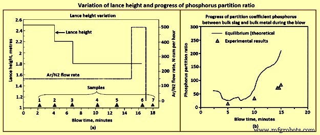
Fig 7 Variation of lance height and progress of phosphorus partition ratio
As the bath becomes low in C in the final phase of the blow, the rate now gets limited by C diffusion within the droplet even as it enters the emulsion. The CO generation is low and is not able to keep the droplets floated. The residence time drops down to a few seconds, and hence number of droplets in the emulsion comes down even though the lance height has been brought down to the lowest level permissible for lance health. The emulsion dies down. At this time there is falling rates of decarburization and fast buildup of FeO in the slag. Since the rates are low, the FeO content and the O2 dissolved in steel increase much beyond what is dictated by C-O equilibrium. Hence, at this period, the operator raises the argon stirring rate, increasing thereby the droplet generation rate without adding extra O2. This helps to some extent.
Phosphorus removal is sometimes an issue in the BOS process and can result in re-blows, especially when the input P in the hot metal is high (around 0.2 %). Though the conditions are normally favourable in the final slag with high FeO and high basicity, the converter operator can land in adverse situation if the slag regime is not carefully managed throughout the blow. The thermodynamics of P is well known. The reaction is written either in terms of molecular species or in the ionic form. The reaction is 2P + 5/2 O2(g) =P2O5(l), P + 5/4 O2(g) + 3/2 (O)2− =(PO4)3−. In the former case one writes an equilibrium constant, and expresses the Raoultian activity coefficient as a function of slag composition. If one adopts an ionic form of the equation, one instead writes an equation for a phosphate capacity of slag and correlates the phosphate capacity to the slag composition empirically. Both these approaches are conceptually similar. The partial pressures of P and O2 can easily be converted to percent dissolved in metal or activity of FeO in slag with known thermodynamic data. The slag data as a function of composition either as Raoultian activity coefficient or as phosphate capacity have been empirically determined in several studies. The progress of partition coefficient for P between bulk slag and bulk metal can be calculated when the slag analysis during the blow is known.
In the initial period of the blow, the bath C is quite high and also contains Si. Hence at the slag / metal interface, the O2 potential remains low. Therefore, very high rate of dephosphorization at the bulk metal / slag interface is not expected. The metal droplets, on the other hand, get highly refined in a matter of 1 min to 2 min, and before returning to the metal bath, have high O2 potential at its interface. Further the partition coefficient at this time is high since FeO content is high due to soft blow, temperature is low, although with some CaO yet to dissolve. The number of droplets in the emulsion is also very large. Hence, the dephosphorization rate is very high which can be seen in Fig 3a. Towards the end of the blow again, the conditions in the slag are favourable with high FeO and high basicity, though now the temperature has risen substantially. The rate of phosphorus removal however is not very high in this period, since the number of droplets is not very high, surface area is quite small and hence all reactions are slow.
Vigorous Ar stirring is helpful at this time of the blow, and for some time after the O2 flow is stopped, though to a limited extent. It is in the middle part of the blow the operator has the highest opportunity for efficient overall dephosphorization. After the soft blow when the lance is lowered progressively for effecting high rates of decarburization, FeO content in the slag drops considerably and remains low till the emulsion starts collapsing. The slag becomes comparatively ‘dry.’ The partition coefficient becomes adverse, and one can easily get P reversal to the metal. Lower is the FeO level, higher is the reversal. This reversal increases the load on the last part of the blow where the rates of reactions are anyway low as explained earlier.
Hence, close control of the FeO content during the middle part of the blow is necessary if the operator is required to make low P steel. Premature lowering of the lance in each stage can lead to very low FeO content (less than 12 % to 15 %). FeO content is determined by the balance between droplet generation rate (consumption rate) and the FeO generation rate. However, it is to be noted that very low FeO in the slag also lowers the decarbonization rate. Very high FeO on the other hand leads to sloppy conditions.
Higher levels of FeO content can be achieved by modifying the lance practice. The lance height for the intermediate levels can be kept slightly higher than the normal. The operator can also slightly delay lowering of the lance, taking care to see that it does not lead to uncontrolled emulsion build up. The operator can also achieve this by distributed ore addition during this period.
The chemistry of steelmaking in BOS converter is summarized here. From the thermodynamics of the O2 steelmaking process, it can be seen that, at the beginning, the O2 blown onto the HM preferably reacts with the dissolved Si, forming SiO2 which floats on the surface of the metal. From kinetics, it is expected that a part of the O2 blown reacts with the dissolved C and Fe atoms. The formation of CO gas occurs instantaneously on process ignition. Calcined lime is added to neutralize the acid slag, which initially includes a liquid mixture of FexOy and SiO2. Several chemical reactions take place in the BOS converter. The main reactions are dissolution of O2 into the metal from O2 gas, decarburization through dissolved O2, and oxidation of Fe, [Si], [Mn], [P], [V] and [Ti]. Solid or liquid oxides are formed as reaction products during blowing, and they are bound with the lime which is added at the start of blowing to form a liquid slag in the converter. Due to intensive CO gas formation, droplets of liquid metal are introduced into the slag, which tends to foam. Hence, the slag in the converter during O2 blowing is actually an emulsion of liquid slag and metal droplets, foaming because of the influence of gas bubbles. The emulsion is also a favourable site for reactions. For example, a considerable fraction of C oxidation can occur in the metal droplets in the emulsion although the majority takes place in the impact zone of the O2 jets. The rest of the O2 is used to burn Fe into FexOy. During blowing, O2 penetrates the metal droplets and can react with the CO gas. The total slag-gas system behaves as foam and rises quickly to the cone of the converter. Hence, the O2 inflow and the reaction rates have to be adjusted so that foam is not spilled from the converter. Slopping frequently occurs even though the inner volume of the converter is almost nine times larger than the volume of the inactive metal and slag bath.
制造工艺