

钢铁洁净度和洁净钢铁技术
钢清洁度和清洁钢技术
钢材的洁净度是决定钢材质量的重要因素。对钢材的抗拉强度、成型性、韧性、焊接性、抗开裂性、耐腐蚀性、抗疲劳性等性能有显着影响。钢材消费者对钢材机械性能的要求越来越高。生产商提高钢材的清洁度。
在当前环境下,提高钢材洁净度已成为钢铁行业的必然趋势。它指导了二次炼钢工艺的发展。这些发展背后的驱动力是使新钢能够承受高要求的应用,例如汽车行业的传动部件,以及用于腐蚀性和腐蚀性环境的建筑零件和管材。
洁净钢是指不含夹杂物的钢。夹杂物是嵌入钢基体中的非金属颗粒。除了降低非金属氧化物夹杂物并控制其形态、成分和尺寸分布外,清洁钢还需要降低其他残留杂质元素,如磷(P)、硫(S)、总氧(O2)、氮( N2)、氢 (H2),有时还有碳 (C),以及微量元素,例如砷 (As)、锡 (Sn)、锑 (Sb)、硒 (Se)、铜 (Cu)、铅 (Pb)、和铋 (Bi)。这些杂质元素因钢种不同而不同。有些元素对某些钢种有害,但对另一种钢种的危害较小甚至有用。也就是说,对于钢材的不同性能要求,控制元素是不同的。
为了在钢中获得令人满意的清洁度,有必要在整个炼钢过程中控制和改进广泛的操作实践。其中包括 (i) 添加脱氧剂和铁合金,(ii) 二次冶金处理,以及 (iii) 护罩系统和铸造实践。
清洁钢发展史
“清洁钢”一词是在 20 世纪中叶创造的。这是全球钢铁产量开始增加的时期。当时的理解是,钢材的质量也被认为是一个特殊而重要的问题。从那时起,炼钢技术的进步导致开发出许多杂质含量极低的钢种。近年来,为了满足钢铁消费行业当前和未来的质量要求,已经开发出新的“清洁和超清洁”钢并将其商业化。钢的清洁度还显着提高了钢的力学性能(如疲劳强度和冲击韧性)和耐腐蚀性。
洁净度的概念最初源于 20 世纪中叶新兴的金相学科在光学显微镜下对非金属夹杂物 (NMI) 的观察。根据微观领域的标准图像对清洁度进行评级,其中 NMI 的几何形状(形状和大小)和分布与各种图像类型进行了区分。受过训练的观察者已经确定,某些钢种的某些形状是可以接受的,并且通常较小的夹杂物比较大的夹杂物更容易接受。虽然当时还没有夹杂物的成分,但观察者已经根据钢的 S 含量和脱氧历史,建立了等级和夹杂物成分之间的对应关系(硫化物、硅酸盐、铝酸盐、氧化铝和复合夹杂物)。
这些在 20 世纪发展起来的方法很快就被标准化了。他们抢先使用二次炼钢工艺和钢的连续铸造。清洁度概念的进一步发展通过并行探索与炼钢物理化学相关的各种问题、新工艺反应器的开发以及控制夹杂物成分、形状、大小和分布的新的创新解决方案而继续进行。炼钢实践的套路。在最初的 30 年到 40 年间,这种建立概念的努力已经形成了现代的清洁愿景。此外,钢的洁净度这一课题目前已经达到了一定程度的成熟,特别是对于新的二次炼钢工艺和连铸工艺生产的钢。
非金属夹杂物
NMI 由嵌入钢基体中的玻璃陶瓷相构成。钢中NMIs的存在是影响钢洁净度的主要原因。钢中的 NMI 有多种来源,其中包括:
脱氧产品 – 这种夹杂物的例子是氧化铝 (Al2O3) 夹杂物,它会导致低碳铝 (Al) 镇静 (LCAK) 钢中的大部分原生夹杂物。这些夹杂物是由溶解的 O2 与添加的脱氧剂(如 Al)之间的反应产生的。 Al2O3 夹杂物在高 O2 环境下形成树枝状,或由较小颗粒的碰撞产生。
再氧化产物 – 这种夹杂物的例子是 Al2O3 夹杂物,当 (i) 残留在钢水中的 Al 被渣中的 FeO 氧化,或 (ii) 钢水暴露在大气中时,会产生 Al2O3 夹杂物。
夹渣 – 当冶金熔剂在炼钢容器之间的转移过程中夹带时,会发生夹渣。夹渣形成液态包裹体,一般呈球形。
外来夹杂物 – 这些夹杂物来自其他来源,例如松散的污垢、破碎的耐火砖和耐火衬里颗粒。它们通常很大且形状不规则。它们可以作为Al2O3异相成核的场所。
化学反应夹杂物 – 这些夹杂物是Ca(钙)处理不当时夹杂物变质的产物。
夹杂物尺寸分布非常重要,因为大夹杂物对钢的机械性能最有害。一公斤 LCAK 钢通常含有 10,000,000 到 1000,000,000 个夹杂物,其中尺寸为 80 微米到 130 微米的夹杂物只有 400 个,尺寸为 130 微米到 200 微米的夹杂物有十个,尺寸为 200 微米到 270 微米的夹杂物少于一个。显然,检测稀有的大夹杂物是非常困难的。虽然大夹杂物的数量远远超过小夹杂物,但它们的总体积分数可能很大。有时灾难性缺陷是由整个钢炉中的一个大夹杂物引起的。因此,洁净钢不仅要控制钢中的平均夹杂物含量,还要避免大于对产品有害的临界尺寸的夹杂物。
NMI 构成分散在钢基体中的相云,由一组多维参数定义,包括成分、形状、尺寸和分布。这种完整的描述通常不容易获得,与评估清洁度相关的主要问题之一是观察有代表性的样本,以合理的准确性和代表性来估计这些参数。一个困难与大夹杂物(尺寸为 100 微米或更大)有关,这种夹杂物非常罕见,因此很难看到,除非对尺寸非常大的样品进行分析。
另一个问题是由于 NMI 的数量取决于时间(在炼钢车间的工艺时间线中)和温度。因此,仔细和巧妙地收集和分析钢包样品可以对当时的清洁度做出相当好的估计,但它与实心钢的清洁度几乎没有任何联系。因此,为了评估钢的成分和 NMI 清洁度,有必要评估何时采集具有代表性的钢水样品。
非金属夹杂物的种类
根据它们的尺寸,夹杂物要么是微夹杂物(尺寸 1 微米到 100 微米),要么是宏观夹杂物(尺寸超过 100 微米)。宏观夹杂物是有害的。微夹杂物是有益的,因为它们会限制晶粒生长,提高屈服强度和硬度。微夹杂物充当碳化物和氮化物沉淀的核。需要删除宏包含。微夹杂物可以通过均匀分散在基体中来增强强化作用。
根据传统的分类,有两种主要类型的 NMI,它们的起源有不同的功能。它们是(i)内源性包涵体和(ii)外源性包涵体(图1)。
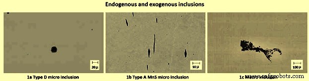
图1内源性和外源性夹杂物
内源性是在熔化和凝固过程中发生的物理化学作用形成的微夹杂物。内源性夹杂物是由于钢中所含化学物质的溶解度降低而在液相中析出而形成的。它也可以由脱氧和脱硫过程或通过再氧化后剩余的 O2 和 S 形成(图 1a 和 1b)。这类NMI不能从钢中完全消除,但必须严格控制其体积分数和平均粒径的降低,以免引发破坏现象。
相反,外源性夹杂物是宏观夹杂物,这是由于夹杂来自熔渣、耐火碎片或上升和覆盖粉末的非金属材料的结果,这些粉末用于保护钢和避免在铸造过程中粘着(图1c) )。属于此类的 NMI 具有尺寸大的特点,并且其来源无法立即识别,尽管它的存在会严重损害钢的微观结构健全性和相关的机械可靠性。
NMI 对钢的质量和性能有很大的影响。这些夹杂物主要是铁(Fe)、锰(Mn)、Al、硅(Si)、Ca等金属与O2、S、N2、C、H2等非金属的化合物。
各种类型的 NMI 是 (i) 氧化物,如 FeO、Al2O3、SiO2、MnO、Al2O3.SiO2、FeO.Al2O3、MgO.Al2O3 和 MnO.SiO2 等。 (ii) 硫化物,如 FeS、CaS、MnS、 MgS、Ce2S3、(iii)氮化物如TiN(氮化钛)、AlN、VN(氮化钒)和BN(氮化硼)等,(iv)氧硫化物如MnS.MnO和Al2O3.CaS等, (v) 碳氮化物,例如钛 (Ti)、钒 (V) 和铌 (Nb) 等的碳氮化物,以及 (vi) 磷化物,例如 Fe3P、Fe2P、Mn5P2。描述氧化物 NMI 化学成分的基本工具是三元相图 (CaO-SiO2-Al2O3),因为这是支配这些非金属化合物形成的主要系统。这类 NMI 是由添加到钢液中以去除 O2 含量的脱氧元素形成的。氮化物夹杂物的不利影响因特殊的边缘形状而恶化,这增加了在NMI和金属基体之间的界面处产生的应力的放大。
根据矿物含量,O2 夹杂物分为(i)游离氧化物,如 FeO、MnO、Cr2O3(氧化铬)、SiO2 和 Al2O3 等,(ii)尖晶石,如铁氧体、铬铁矿和铝酸盐,以及( iii) 硅酸盐,如 SiO2 与 Fe、Mn、Cr(铬)、Al(铝)和 W(钨)氧化物的混合物以及结晶硅酸盐。
NMI 的另一种分类是稳定性。 NMI 相当稳定或不稳定。不稳定的夹杂物是Fe和Mn的硫化物以及一些游离氧化物。
根据夹杂物的形态,夹杂物可以具有 (i) 球状、(ii) 片状或 (iii) 多面体形状。夹杂物的球形是理想的。某些夹杂物如 MnS、硫氧化物、铝酸铁和硅酸盐是球状的。夹杂物的片状形状是不理想的。铝脱氧钢含有沿晶界分布的薄膜形式的 MnS。多面体形状的夹杂物危害不大。
最初与清洁度有关的化学元素大多是门捷列夫元素周期表中的非金属,因为它们在液态钢中的溶解度高于在固体中的溶解度。这些主要是 C、N2、O2、P、S、Se 和 H2。在此列表中,可以添加表中的准金属邻居,例如 B(硼)、As、Sb 和 Te(碲)。其中一些元素来自初级原材料(P、S、As、Sb)或来自高炉的铁水,而其他大多数元素要么来自大气(O2、N2 和 H2)的污染,要么来自用于炼钢的操作实践,或自愿添加(C、Se、Te和B)。
硫化物通常是为了改性氧化物夹杂物而应用 Ca 处理的结果,但少量且精细分散的高耐火 CaS 夹杂物可能对铸件(喷嘴堵塞)和破坏效果有害。相反,MnS NMIs(通常通过与 CaS 结合改性)在钢的加工过程中对刀具的可加工性很有用。
在 NMI 的起源中已经认识到三种主要机制。这些机制与非金属相对金属基体的破坏作用有关。这些机制将 NMI 视为 (i) 放大 NMI 周围应力场的切口元素,(ii) 逐渐迁移到 NMI 中的加压气体罐,在 NMI 周围产生应力场,以及 (iii) 非金属相由于金属相和玻璃陶瓷相的热膨胀系数不同,会产生残余应力。
钢材清洁度的评价方法
准确了解钢中实际的夹杂物含量对于提高钢质量和预测由钢制成的部件的性能至关重要。为了研究和控制钢的清洁度,准确的评价方法至关重要。夹杂物的数量、尺寸分布、形状和成分应在钢铁生产的所有阶段进行测量。测量技术范围从准确但成本高昂的直接方法到快速且成本低廉但仅作为相对指标可靠的间接方法。
直接方法
评价钢材清洁度的直接方法有几种,总结如下。
金相显微镜观察(MMO) – 这是传统的方法,其中通过钢样品进行二维切片,用光学显微镜检查并通过肉眼进行量化。其中,使用 JK 参考量表等图表评估结果。该技术仅适用于鉴定 2 微米至 15 微米之间的夹杂物,并且仅限于非常小的样品尺寸。该方法不提供任何关于夹杂物化学成分的数据。通过复杂形状的夹杂物解释切片时会出现问题。虽然有一些方法可以将二维结果与三维现实联系起来,但这通常是非常有问题的。
图像分析 – 这是对 MMO 的增强,它通过使用视频扫描显微镜图像的高速计算机评估来根据灰度截止区分暗区和亮区,从而改进眼睛评估。与MMO相比,该方法可以轻松评估更大的区域和更多的夹杂物数量,但容易将划痕、麻点和污点误认为是NMI。
硫磺印花 – 这是一种流行且廉价的宏观摄影方法,通过蚀刻富含硫的区域来区分宏观夹杂物和裂缝。它与其他二维方法存在相同的问题。
蓝色断裂测试 – 这是一种历史悠久的技术,用于揭示大于 0.5 毫米的宏观夹杂物。它是在经过硬化、断裂和蓝色回火的钢筋横截面区域进行的,以增加缺陷的可见性。
煤泥(电解)法 – 这是一种准确的方法,但耗时。将相对较大(200 克至 2 千克)的钢样品完全溶解在盐酸 (HCl) 中,收集未溶解的 NMI 用于计数和进一步分析。或者,为了保护 FeO 夹杂物,大部分溶解是通过向浸入 FeCl2 或 FeSO4 溶液中的钢样品施加电流来完成的。该方法用于揭示单个完整的夹杂物。
电子束 (EB) 熔化 – 钢样品在真空下被电子束熔化。夹杂物漂浮到上表面并在熔融样品的顶部形成一个筏。通常的EB指数是包含筏的特定区域。已经开发了一种增强的方法 EB-EV(极值)来估计夹杂物尺寸分布。这是通过测量筏的几个区域的最大夹杂物尺寸并在整个筏上推断结果来完成的,假设夹杂物尺寸分布呈指数分布。
冷坩埚 (CC) 熔炼 – 夹杂物首先集中在熔化样品的表面,就像在 EB 熔化中一样。冷却后,样品表面溶解,夹杂物从溶质中滤出。该方法改进了粘液的提取。
扫描电子显微镜 (SEM) – 该方法清楚地揭示了所检查的每个夹杂物的 3D 形态和成分。成分用电子探针微量分析仪(EPMA)测量。 SEM 能够评估大面积并提供关于夹杂物化学、形态和尺寸的丰富数据。
具有脉冲辨别分析 (PDA) 的光学发射光谱法 (OES) – OES 方法通常用于分析钢中的溶解元素。该技术已得到进一步改进,可在采集样品后 10 分钟内分析总 O2 含量、微夹杂物尺寸分布和成分。为了区分固体夹杂物 (OES-PDA),以发射火花的频率进行光测。定义电特性以优化溶解元素的背景信号与由于夹杂物等异质性引起的干扰信号之间的光比。高强度Al峰火花数即为PDA指数。
通过分析冲浪板 (MIDAS) 检测曼内斯曼夹杂物 – 钢样先经过轧制去除气孔,然后超声波扫描检测固体夹杂物和复合固体夹杂物/气孔。这种方法最近被重新发现为“液体取样热轧(LSHP)方法。
激光衍射粒度分析仪(LDPSA) – 这种激光技术可以评估使用另一种方法(例如粘液)从钢样品中提取的夹杂物的尺寸分布。
常规超声波扫描 (CUS) – 该方法可以得到凝固钢样品中大于20微米的夹杂物尺寸分布。
锥形样品扫描 – 在这种方法中,使用螺旋检测器(例如固体超声波系统)扫描锥形体积的连续铸钢,该检测器会自动检测样品区域中每个位置的表面夹杂物,包括从表面到中心线。
部分热分解 (FTD) – 不同氧化物的夹杂物在不同温度下被选择性还原,如Al2O3基氧化物在1400℃到1600℃,或难熔夹杂物在1900℃。总O2含量是每次加热时测得的O2含量之和一步。
激光微探针质谱 (LAMMS) – 单个粒子被脉冲激光束照射,并且由于其化学状态而选择了高于电离阈值的最低激光强度,因为其特征光谱模式。通过与参考样品结果的比较,LAMMS光谱中的峰与元素相关。
X射线光电子能谱(XPS) – 该方法使用 X 射线来绘制大于 10 微米的夹杂物的化学状态。
俄歇电子能谱 (AES) – 该方法使用电子束映射光散射法的化学状态。分析夹杂物的光散射信号(使用其他方法如粘液从钢样品中提取),以评估尺寸分布。
液态金属清洁度分析仪 (LIMCA) – 这是一种在线传感器,可直接检测液体中的夹杂物。通过其小孔流入该传感器的颗粒会被检测到,因为它们会改变间隙的电导率。
库尔特计数器分析 – 该方法类似于LIMCA,可用于测量由粘液提取并悬浮在水中的夹杂物(大于亚微米的夹杂物)的粒度分布。
液体系统的超声波技术 – 该方法通过捕获超声波脉冲的反射来在线检测钢液中的夹杂物。
浸入式超声波探伤法 – 它用于测试较大的夹杂物并产生令人印象深刻的结果。为了测试尺寸超过 120 微米的夹杂物,使用 10 MHz 探头扫描一个 500,000 立方厘米的钢样品,平行铣削平面并浸入水箱中。这相当于 16,000 次蓝色断裂测试。该测试不会产生有关夹杂物化学成分的信息,但它是该过程的重要工具。为了测试较小的夹杂物,可以将超声波探头的频率提高到 15 MHz、25 MHz、50 MHz 甚至更高。然而,随着频率和分辨率的增加,采样体积的大小会减小。
间接方法
由于成本、时间要求和取样困难,钢铁行业通常采用总 O2、N2 吸收量和其他间接方法来测量钢的清洁度。
总氧气测量 - 钢中的总 O2 是游离 O2(溶解的 O2)和结合为 NMI 的 O2 的总和。使用 O2 传感器可以相对容易地测量游离 O2 或“活性”O2。它由具有脱氧元素(例如 Al)的平衡热力学控制。由于游离 O2 变化不大,因此总 O2 是钢中氧化物夹杂物总量的合理间接量度。由于钢中大夹杂物的数量很少,而且总 O2 测量的样本量很小(通常为 20 g),因此样品中可能没有大夹杂物。即使样本包含大量内容,也可能会因为异常高的读数而被打折。因此,总 O2 含量真正代表了小氧化物夹杂物的水平,而不是较大的氧化物夹杂物。然而,低总 O2 含量会降低大氧化物夹杂物的可能性。因此总O2仍然是一个非常重要和常用的钢清洁度指标。随着新技术的实施,LCAK 钢中的 O2 总量随着时间的推移而稳步下降。例如,与仅采用钢包气体搅拌(35 ppm 至 45 ppm)的钢厂相比,采用真空脱气的钢厂实现的总 O2(10 ppm 至 30 ppm)更低。总O2通常在每个加工步骤后下降,例如钢包40 ppm,中间包25 ppm,结晶器20 ppm,铸钢15 ppm。
N2 接送 – 炼钢容器(特别是钢包和中间包)之间 N2 含量的差异是转移操作过程中夹带空气的指标。脱氧后,钢中溶解的 O2 含量低,可以快速吸收空气。因此,N2 吸收量可作为总 O2、钢清洁度和再氧化夹杂物质量问题的粗略间接测量。随着新技术的实施和操作的改进,N2 的回升多年来已经停止。通常,从钢包到模具的 N2 吸收量可以控制在 1 ppm 到 3 ppm。通过优化转移操作以减少空气夹带,在稳态铸造过程中,N2 的吸收量可以降低到 1 ppm 以下。在大多数钢厂中,LCAK 钢中的 N2 水平通常控制在 30 ppm 到 40 ppm 水平。主要受炼钢转炉或电炉操作控制,但受精炼和包覆操作影响。
溶解铝损失测量 – 对于 LCAK 钢,Al 损失也表明发生了再氧化。然而,这种方法不如 N2 提取准确,因为 Al 也可以被炉渣再氧化。
渣成分测量- 对操作前后炉渣成分演变的分析可以解释为估计夹杂物对炉渣的吸收。此外,可以通过匹配熔渣和夹杂物成分中的微量元素来确定特定容器的夹渣。
浸入式喷嘴 (SEN) 堵塞 – 由于堵塞导致的 SEN 寿命短通常表明钢的清洁度较低。已知 LCAK 钢中的少量 Al2O3 夹杂物会导致喷嘴堵塞。因此,SEN堵塞频率是评价钢材清洁度的另一种粗略方法。
因此,可以看出没有单一的理想技术来评估钢的清洁度。有些技术更适合质量监控,而另一些技术则从问题调查的角度更好。因此,有必要将几种方法结合在一起,以更准确地评估钢铁厂的钢材清洁度。对夹杂物的可靠量化为开发新一代清洁钢提供了可能。
清洁钢的技术和操作实践
二次炼钢已成为管理钢水清洁度的公认工具,因为它不仅可以在受控条件下向钢水添加添加剂,而且有助于仔细搅拌渣-金属、减渣、温度修整、夹杂物聚结、消除通过浮选和截留在炉渣和成分控制、真空脱气和有时 C 脱氧等。因此,工程钢所需的功能已可供钢铁生产商使用,其中一部分用于所有等级的钢,这已经使商业质量和特种钢之间的区别有点模糊。
二次炼钢和连铸的一个重要特点是冶金功能沿着设备线在空间中展开,按照时间尺度展开,因此它们可以标准化,有时可以自动化,并且可以更好地控制。另一方面,污染源成倍增加,但也可以得到更好的控制。钢包到中间包(钢包水口、滑动浇口、钢包流气体保护等)、中间包(粉末、堰、挡板和鼓泡元件等)、中间包到模具(水口、滑动门或塞棒、浸没式喷嘴和气体鼓泡等)、结晶器(结晶器粉末、结晶器液位控制、浸入式水口几何形状等)、连铸本身(直、弯曲结晶器、直结晶器和弯曲结晶器、电磁搅拌、电磁制动和横向结晶器)薄板坯连铸机等),所有这些都已成为工艺链的一部分,并变成真正的冶金反应器。 “中间包冶金”这个说法已经很普遍,连铸机,尤其是其结晶器,也充当着冶金反应器的角色,NMI 的命运将继续被决定。
这些在二次炼钢过程中为提高钢的清洁度而进行的大量技术和操作实践,包括添加脱氧剂和铁合金的时间和地点,二次炼钢过程的范围和顺序,搅拌和转移操作, 护罩系统, 中间包几何形状和实践, 各种冶金熔剂的吸收能力, 和铸造实践。
NMIs 化学成分的形成和控制涉及生产过程的不同步骤和执行它们的工业系统。必须在每个步骤中仔细实施生产过程,以避免出现以下问题(铸锭工艺),以及(ii)对钢的力学性能的不利影响。
在 BOF(碱性氧气炉)或 EAF(电弧炉)炼钢结束时,O2 与 C 处于平衡状态,这意味着低 C 钢等级的氧气含量非常高(0.02 % C 为 1250 ppm O2)。如果钢就这样简单地凝固,则 Fe、S 和 O2 的共晶析出在枝晶间,而在凝固的初始阶段发生强烈的 C 脱氧,从而生产出表面附近充满气孔的钢圈。所得钢除了多孔外,在热轧或热锻操作以及随后在室温下使用时也很脆。
为避免析出 O2 和 S 铁共晶,在工艺中引入脱氧剂(C,特别是在减压下,Mn、Si、Al、Ca 和 Ti 等)和脱硫剂(Mn 和 Ca)以促进新的平衡,其中第三相沉淀和边缘完全避免。第三相构成了内源性 NMI(氧化物、氮化物、碳化物、硫化物和磷化物等),它们最初是在钢水中产生的,通常是在钢包中。这些平衡可以通过在钢水中加入脱氧剂来实现,通过批量添加或线材注入或确保液态金属与适当成分的活性冶金渣达到平衡。
The population NMIs changes all the time, since the existing inclusions coalesce, float out and get finally adsorbed in a slag or a simple covering powder or flux, by aggregation against refractory in the ladle, the tundish or inside nozzles that some of them (solid non-metallic inclusions, like Al2O3 or spinels) tend to clog. Steel and slag change as well, and inclusions entertain complex connection with them, at equilibrium, if time allows, or out of it. Gas evolution at the solidification front can still take place if N2 and H2 are not properly controlled. More inclusions appear, since temperature drops, which generally means more precipitation, or solidification starts, or O2 penetrates the system (reoxidation),from the slag, the refractories, from the atmosphere at refractory junctions (sliding gates, submerged nozzle mounting, and across the refractories etc.), or because the slag or the refractories generate new inclusions or release inclusions previously captured. The latter is known as the exogenous NMIs. Of course, the trend is generally towards improved cleanliness with all these mechanisms are being deeply looked into for finding counter-measures.
An important point regarding reoxidation is that the phenomenon does not take place at thermo-dynamic equilibrium, but rather generates oxides of whichever element happens to meet the incoming O2, most often generating Fe oxides. Out of the equilibrium in deoxidized liquid steel, these oxides later reverse back to equilibrium NMIs, if time permits.
The distinction between endogenous and exogenous NMIs is however somewhat ad-hoc, as deoxidation or reoxidation are actually an integral parts of the total process of the steelmaking and both result from the technology put in place to produce steel. As an example, deoxidation does not take place inside liquid steel, but at the interface of the deoxidizing agent injected.
NMIs are large enough to interact with the metal matrix as mechanical discontinuities, basically like holes. There are other third phases in steel of much smaller dimensions called precipitates, which interact with the matrix as the scale of dislocations or even at atomic scale. Precipitates, normally carbides or nitrides, constitute the key features of the micro-alloying of steels or of more substantial alloying like in tool steels or in stainless steels.
Steel refining and continuous casting operations have important effects on improving steel cleanliness. A systematic study of inclusion removal carried out in a steel plant has indicated that the ladle treatment drops inclusions by around 65 % to 75 %, the tundish removes inclusions by around 20 % to 25 %, although reoxidation can sometimes occur, and the mould removes inclusions around 5 % to 10 % of the total inclusions.
Ladle operations
The tap O2 content is measured during tapping the liquid steel in the ladle or before the addition of the deoxidizing agents. The value is typically high. It varies in a wide range (250 ppm to 1200 ppm) depending on the primary steelmaking practice. Al additions when used to deoxidize the steel, create larger amounts of Al2O3. This suggests that a limitation on tap O2 content is to be imposed for clean steel grades. However, there is no correlation between furnace practice and steel cleanliness, since around 85 % of the Al2O3 clusters formed after large additions of Al, float out to the ladle slag, and that the remaining clusters are smaller than 30 microns. Naturally, the decision to ignore tap O2 depends on the time available to float inclusions and on the availability of ladle refining, which can remove most of the generated inclusions. However the tap O2 content strongly affects the decarburization rate for producing ultra low C steel.
FeO and MnO in slag – An important source of reoxidation is the carryover slag from the converter to the ladle, which contains a high content of FeO and MnO. These oxides react with the dissolved Al to generate Al2O3 in liquid steel, owing to the strong favourable thermodynamics of the reactions 3FeO (l) + 2Al =Al2O3 + 3Fe (l), and 3MnO + 2Al =Al2O3 + 3Mn (l). The higher is the FeO and MnO content in the ladle slag, the greater is the potential for reoxidation and the corresponding generation of the Al2O3 inclusions. Many slivers in the final product have been traced to reoxidation that originated from FeO in the ladle slag.
Many counter-measures can be adapted to lower FeO and MnO contamination. These counter-measures are (i) minimizing of slag carryover from converter to ladle during tapping, (ii) increasing aim turndown C, (iii)avoiding the reblows, thus minimizing the dissolved O2 content in the steel and reduce the amount of FeO in the furnace slag, (iv) use of a sub-lance in the BOF substantially reduces the frequency of reblows, (v) use of an efficient mechanical slag stopper, such as a slag ball (which floats in steel and sinks in slag), and (vi) using other sensors which are alternatively available. A thick ladle slag layer after tapping suggests high slag carryover problems. In some plants, the ladle slag for critical grades is mechanically skimmed at the ladle furnace to a thickness in the range of 25 mm to 40 mm.
Ladle slag reduction treatment – It has been found that minimizing slag carryover, together with adding a basic ladle slag and basic lining to lower the ladle slag to less than 1 % to 2 % of FeO + MnO, can reduce total O2 content to 10 ppm for LCAK steel. Another way to lower the FeO + MnO content of the ladle slag is to add a slag conditioner (i.e. slag reduction or deoxidation treatment), which is a mixture of Al and burnt lime or limestone. There is a drop in FeO + MnO content after ladle slag reduction treatment. On an average, this treatment lowers the FeO + MnO level to below 5 %. This results in sharp improvement of coil cleanliness.
Effect of vacuum treatment and ladle stirring – Vacuum treatment of liquid steel started with the production of engineering steels for the automotive, power, and the aircraft sectors with the purpose of increasing the reliability and life of the mechanical parts of vehicles or nuclear reactors. The major need is to control the H2 level in liquid steel (to less than 1 ppm in a C steel) in order to avoid its departure at solidification and its entrapment in the solid, which leads to serious integrity defects during the use of the steel part. The use of vacuum, which removes H2 straight forwardly, came into existence in the steelmaking shops, using various technologies like tank degassing, stream degassing, and DH and RH (Rheinstahl Heraeus) ladle degassing processes. The vacuum degassing besides reducing the non-metallic inclusions, also allows other benefits such as (i) C deoxidation, which has the major advantage of producing gaseous deoxidation products, (ii) intensive stirring with its several advantages, (iii) allows for the time management in the logistics of ladle flow, hence on the quality of temperature control of liquid steel, and (iv) reheating of the liquid steel by Al and O2 injections.
Ladle stirring and the ladle degassing processes greatly promote inclusion growth and removal. The effect of vacuum treatments on the cast steel inclusion levels shows the improvement of steel cleanliness over argon (Ar) stirring in the ladle. The pronounced benefit of Ca-based powder injection is due to its greater stirring power in addition to its primary effect of deoxidization and liquefying inclusions. The vacuum degassing and Ca treatment together can drop the total O2 to 15 ppm level.
However, excessive stirring is detrimental, since the upward circulation of steel onto the slag layer can expose an ‘eye’ region of the steel surface to reoxidation as well as due to the refractory erosion. Sufficient stirring time (more than 10 min) after the addition of ferro-alloys is also important, to allow the Al2O3 inclusions to circulate upto the slag and be removed. In some plants, the practice of first stirring vigorously to encourage the collision of small inclusions into large ones, followed by a ‘final stir’ which slowly re-circulates the steel to facilitate the removal of inclusions into the slag while minimizing the generation of more large inclusions via collisions.
Tundish operation
Important phenomena which are taking place in the tundish are shown the Fig 2. The factors which are affecting the steel cleanliness are (i) casting transitions, (ii) tundish refractory lining, (iii) tundish flux, (iv) gas stirring, and (v) tundish flow control.
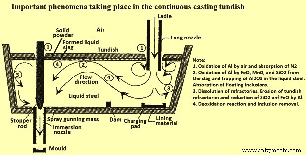
Fig 2 Important phenomena taking place in the continuous casting tundish
Casting transitions – Casting transitions occur at the start of casting, during ladle exchanges and SEN (submerged entry nozzle) changes, and at the end of the casting sequence. Inclusions are often generated during transitions and can continue for a long time, hence contaminate a large quantity of steel. During these unsteady casting periods, slag entrainment and air absorption are more likely, which induce reoxidation problems
During the first casting heat, the entrainment of air and slag in the tundish pour box due to the turbulence during ladle open is accompanied by an initial maximum in total O2 content in the tundish (including both slag and Al2O3 inclusions). Open pouring at the start of the casting causes total O2 in tundish to increase to twice normal levels for more than an entire heat. Several minutes of filling are needed before tundish flux can be added. Eventually, during steady casting, the total O2 decreases to lower levels, consisting mainly of Al2O3.
One improvement during ladle transitions is to stop the flow of liquid into the mould until the tundish is filled and to bubbling gas through the stopper to promote inclusion flotation. Another improvement effect is to open new ladles with submerged shrouding. With this measure, the total O2 is decreased with more consistent quality throughout the sequence. Near the end of a ladle, ladle slag can enter the tundish, due in part to the vortex formed in the liquid steel near the ladle exit. This phenomenon needs some steel to be kept in the ladle upon closing (example 5 ton ‘heel’). In addition, the tundish depth drops after ladle close, which disrupts normal tundish flow and can produce slag vortexing, slag entrainment, and increased total O2 in the mould.
Tundish refractory lining – Dissolved Al in the liquid steel reacts with an O2 source in the lining refractory. The extent of this reaction can be quantified by monitoring the Si content of the liquid steel. The O2 for the reaction can come from CO (carbon monoxide) when C in the refractory reacts with binders and impurities or from SiO2 refractory decomposition. SiO2 based tundish linings are worse than MgO based sprayed linings.
Tundish flux – The tundish flux is to carry out many functions. Firstly, it is to insulate the liquid steel both thermally (to prevent excessive heat loss) and chemically (to prevent air entrainment and reoxidation). Further, the tundish flux with lower SiO2 content can decrease N2 pick-up from the ladle to the mould substantially. Secondly, in ideal circumstances, the flux is also to absorb inclusions to provide additional steel refining. A normal tundish flux is burnt rice husk, which is inexpensive, a good insulator, and provides good coverage without crusting. However, rice husk is high in SiO2 (around 80 %), which can be reduced to form a source of inclusions. Also, rice husk is very dusty and with their high C content, (C around 10 %), can contaminate ultra low C steel.
Basic flux (CaO-Al2O3-SiO2 based) is theoretically better than burnt rice husk at refining LCAK steels, and has been correlated with lower O2 in the tundish. Use of basic tundish flux (CaO-40 %, Al2O3-24 %, MgO-18 %, SiO2-5 %, Fe2O3-0.5 %, and C-8 %), together with baffles, significantly lowers the total O2 fluctuation, as compared to the flux (CaO-3 %, Al2O3-10 % to 15 %, MgO-3 %, SiO2- 65 % to 75 %, and Fe2O3-2 % to 3 %). The basic flux, however, show similar results for other parameters as compared to rice husk, may be because the basic flux also contains a high content of SiO2. The basic flux is thus ineffective since it easily forms a crust at the surface, owing to its faster melting rate and high crystallization temperature. Also, basic flux normally has lower viscosity, and hence it is more easily entrained. To avoid these issues, some steel plants use a two-layer flux, with a low-melting point basic flux at the bottom to absorb the inclusions, and a top layer of rice husk to provide insulation, which lowers the total O2.
Tundish stirring – Injecting inert gas into the tundish from its bottom improves mixing of the liquid steel, and promotes the collision and removal of inclusions. This technology lowers the total O2 in the tundish. The danger with this technology is that any inclusions-laden bubbles which escape the tundish and become entrapped in product result into severe defects in the product.
Tundish flow control -The tundish flow pattern is to be designed to increase the liquid steel residence time, prevent the ‘short circuiting’ and promote inclusions removal. Tundish flow is controlled by its geometry, level, inlet (shroud) design, and flow control devices such as impact pads, weirs, dams, baffles, and filters. The tundish impact pad is an inexpensive flow control device which suppresses turbulence and prevents erosion of the tundish bottom where the liquid steel stream from the ladle impinges the tundish. The incoming stream momentum is diffused and allows the naturally buoyancy of the warm incoming steel to avoid short circuiting, particularly at startup. Together with weir and dam, the impact pad improves steel cleanliness, especially during ladle exchanges.
Transfer operations
One of the most important sources of O2 pick-up is atmospheric reoxidation of steel during the transferring from ladle to tundish or from tundish to mould. This generates inclusions which cause production problems such as nozzle clogging, in addition to defects in the final product. Optimization of shrouding system is very important to prevent this phenomenon. Using a shroud lowers the N2 pick-up relative to open pouring. Replacing the tundish pour box with a ladle shroud and dams also lowers the N2 pick-up (ladle to tundish) and also lowers the slag entrainment during transitions.
Ladle opening – Ladle self open is a heat in which the ladle nozzle does not have to be lanced open, but opens on its own. When the nozzle is to be lanced open, then the shroud is to be removed. The cast is unshrouded from ladle to tundish during the first 600 mm to 1200 mm of the cast, and hence the reoxidation by air occurs. Hence, the total O2 level for the self-open ladle is lower than the lanced-opened ladle. Careful packing ladle opening sand is helpful to realize ladle self open.
Argon protection – Argon protection is used to prevent the liquid steel from air reoxidation. When adding the tundish flux too early, the flux can be entrapped into liquid steel and cast into the steel, thus normally there is no protective cover for the first few minutes of a cast. Also at the period of ladle opening, air is very easy to reach liquid steel. The effects of these two factors can last upto 15 minutes into the cast for a tundish of 60 ton capacity. For countering this problem, purging the tundish with inert gases (to displace the air) prior to opening the ladle into the tundish is adopted in some steel plants. Another measure to improve shrouding system for lowering of total O2 is to incorporate an appropriate gas injection.
Sealing issues –For decreasing the N2 pick-up during continuous casting, the factors normally considered are sealing of shroud from ladle to tundish, and SEN from tundish to the mould.
Nozzle clogging – In addition to interfering with production, the clogging of tundish nozzle and SEN is detrimental to steel cleanliness for three reasons. Firstly, dislodged clogs either become trapped in the steel, or they change the flux composition, leading to defects in either case. Secondly, clogs change the nozzle flow pattern and jet characteristics leaving the nozzle, which disrupt flow in the mould, leading to slag entrapment and surface defects. Thirdly, clogging interferes with mould level control, as the flow control device tries to compensate for the clog. Several practices can used to minimize clogging. In addition to taking general measures to minimize inclusions, clogging via refractory erosion can be countered by controlling nozzle refractory composition, (example avoiding of Na, K, and Si impurities), or coating the nozzle walls with pure Al2O3, BN, or other resistant materials.
Mould and continuous casting machine (CCM) operation
The casting of liquid steel in a continuous casting machine (CCM) involves many phenomena, shown in Fig 3, which have far reaching consequences on the strand quality. Inclusions carried into the mould through the nozzle include deoxidation products, nozzle clogs, and entrained of tundish/ladle slag (reoxidation by SiO2, FeO, and MnO in the slag), and reoxidation products from air absorption from nozzle leaks. Mould slag can be entrained by excessive top surface velocities or level fluctuations. New inclusions can precipitate as the superheat drops, such as TiO2 inclusions in Ti-treated steels. On the other hand, inclusions can be removed into the slag/steel interface by buoyancy flotation, fluid flow transport, and attachment to the bubble surfaces.
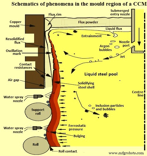
Fig 3 Schematics of the phenomena in the mould region of a CCM
The mould is the last refining equipment where inclusions are either safely removed into the top slag layer or get entrapped into the solidifying shell to form permanent defects in the cast product. Important insight into inclusion entrapment has been obtained in the past through collecting statistical data and conducting trials on the operating CCMs. It has been noticed that increasing steel flow rate increases the level of pencil blisters (from Ar bubble entrapment) considerably, while it reduces the level of slivers (from slag entrapment). While measuring the inclusion and bubble distribution in the cast steel, it has been observed that individual 1 mm bubbles are often coated with inclusion clusters, and can be carried from far upstream, even if no gas is injected into the tundish nozzle. It has been also observed that the inclusion entrapment varies from side to side, which suggests a link with variations in the transient flow structure of the lower recirculation zone.
Defects are frequently found associated with transients in the process, such as changes in casting speed, tundish changes, or clogged nozzles. Pencil pipe defects occur intermittently and are rare, relative to the quantity of injected gas. The conclusions made in one of the study are that 80 % the particle are eventually removed to meniscus (20 % entrapped in cast product), and a given particle circulate for upto 300 seconds before being removed or entrapped.
In a CCM with curved-mould, inclusions are preferentially trapped 1 m to 3 m below the meniscus. Thus, inclusions concentrate at one-eighth to one-quarter of the thickness from the top of the inside radius surface, in addition to the surfaces. It has also been reported that the electromagnetic stirring can improve the steel cleanliness by lowering the total O2 content in the cast product. CCM with curved mould machines are known to entrap many more particles than the CCM with straight (vertical) mould, since the inclusion spiral upwards the inside radius, where they collect at a specific distance through the thickness , corresponding to 2 m to 3 m below the meniscus.
It has been reported that the cast speed has its effect on the slivers. High speeds and high variation in casting speed result in a higher rate of slivers. Adequate stable casting speeds can be obtained with the use of a stopper. With a stopper, the speed is no longer determined by the level of steel in the tundish, but by the level of steel in the mould. It is better to control mould level control in the range +/- 3 mm. A beneficial tool for the optimizing of the fluid flow and hence improving the quality of the cast product is the electromagnetic brake (EMBR), which bends the jet and shortens its impingement depth, inclusions thus move more upwards, tend to top powder or be captured by the solidified shell at the surface of the cast product. After the use of EMBR, the inclusions distribution shows that there is a shift to the surface of the cast product.
制造工艺