

无粘合剂电极及其在锂离子电池中的应用
摘要
锂离子电池 (LIB) 作为能源供应和存储系统已广泛应用于电子产品、电动汽车和公用电网。然而,提高LIB能量密度的需求越来越大。因此,开发具有高能量密度的新型电极材料显得尤为重要。尽管已经发现了许多新材料,但问题仍然存在:(1)粘合剂和活性材料(金属氧化物、Si、Li、S等)之间的弱相互作用和界面问题,(2)体积变化大,(3) ) 低离子/电子电导率,以及 (4) 在充电和放电过程中活性材料的自聚集。目前,无粘合剂电极是解决上述问题的有希望的候选者。首先,通过将活性材料直接固定在导电基材上,可以解决粘合剂和活性材料的界面问题。其次,无粘合剂电极的孔隙率可以适应活性材料的大体积膨胀。第三,通过导电基材与活性材料的紧密接触,可以提高离子和电子的导电性。因此,无粘合剂电极通常表现出优异的电化学性能。传统的制造工艺包含电化学惰性粘合剂和导电材料,这降低了活性材料的比容量和能量密度。当去除粘合剂和导电材料时,可以大大提高电池的能量密度。本综述介绍了无粘合剂电极的制备、应用和展望。首先,引入不同的导电基材,作为活性材料的载体。其次是从化学、物理和电学角度出发的无粘合剂电极制备方法。随后,介绍了无粘合剂电极在柔性电池领域的应用。最后对这些处理方法和应用进行了展望。
介绍
能源危机和环境问题推动了可再生能源和新型环保储能系统的发展。由于风能、水能、太阳能等可再生能源的间歇性问题,电池被认为是重要的储能系统[1,2,3]。对可靠和高效的能量存储设备的需求不断增加。锂离子电池(LIBs)因其能量和功率密度高、电池电压高、工作温度范围宽和循环寿命长而备受关注[4]。如今,传统的电池制备工艺采用聚偏二氟乙烯(PVDF)作为粘合剂,通过涂覆的方式将导电剂和活性材料固定在集流体上[5, 6]。随着对具有更高容量和更小尺寸的LIB的需求,开发具有高比容量的活性材料和减少电池中的非活性材料都很重要。减少非活性物质的方法如下。首先,可以用导电粘合剂代替传统的粘合剂,例如芘基聚合物和聚芴共轭聚合物。这些聚合物天然具有导电性,它们的侧链或主链经过修饰以增加附着力 [7,8,9,10]。导电粘合剂用作导电剂。因此,可以减少电池中惰性碳的使用。然而,这些粘合剂(PVDF 和新开发的粘合剂)与活性材料(金属氧化物、Si、Sn、Li、S 等)之间的微弱界面相互作用导致颗粒自聚集或/和与集电器隔离。因此,这些具有高容量的新材料显示出电池性能降低 [11,12,13,14,15]。其次,研究了先进的导电基材,例如碳布、石墨烯和泡沫镍,其中活性材料可以锚定在基材的特殊粘附位点上。活性材料和基材之间的粘附是通过强大的化学和/或物理结合实现的,这显着提高了电极的完整性。此外,该过程可能会同时去除粘合剂和导电碳添加剂。因此,能量密度可以大大提高[16, 17](图1)。
<图片>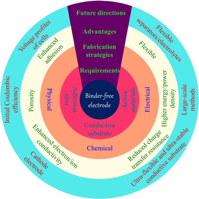
无粘结剂电极的要求、制备方法、优势及未来发展
大量研究已经证明了无粘合剂电极的众多优点 [18,19,20,21]。通过将活性材料固定在相应的电子导电基材上,可以解决粘合剂和活性材料的界面问题,因为活性材料表面上没有有机粘合剂覆盖[22, 23]。活性材料牢固地附着在导电基材上,极大地提高了电子导电性。支撑材料的特性,例如多孔结构,促进电解质渗透和离子扩散 [24]。此外,大的表面积有利于活性材料的充分利用和锂离子的运输。而且,活性材料一般均匀地锚定在导电基材上,可以有效地防止纳米颗粒的团聚,减少重复循环过程中的体积膨胀。无粘合剂电极通常表现出高 Li + 和电子导电性,良好的电解质润湿性和大的体积膨胀空间,结合强度强。因此,无粘合剂电极比 PVDF/活性材料/炭黑体系表现出更好的容量、循环和倍率性能。具体而言,新型纳米材料的循环寿命从几十个循环增加到几百个循环,具有~10 A g -1 的高电流密度 .
作为活性材料载体的导电基材是无粘合剂电极的基础。导电基体需要有合适的位点来生长活性材料,其力学性能对其应用起着决定性的作用。对于电极在可穿戴和柔性电子设备中的应用,导电基板需要能够多次弯曲甚至折叠。这在通过浆料工艺制造的常规电极中是难以实现的。主要原因是在弯曲过程中活性物质与集流体分离,导致电池失活。直接在柔性网络上生长活性材料提供了强大的相互作用,并导致保持高能量密度的坚固电极。这些柔性基板主要包括金属泡沫、碳布和碳材料的自支撑薄膜[25]。
本综述旨在概述 LIB 无粘合剂电极的制备、应用和前景。我们的目标是强调无粘合剂电极的最新发展和改进 [26]。对LIBs领域无疑很重要的刮刀铸造和渗透方法将不包括在内。首先,我们介绍不同的导电基材,它们主要用作活性材料的载体。我们随后从化学、物理和电学的角度介绍了无粘合剂电极的制造方法。随后,介绍了无粘合剂电极在柔性电池领域的应用。最后,对这些制备方法及其应用的关键问题进行了展望。
导电基材
导电基材是具有良好电子导电性的集电器。因此,材料一般由金属或碳材料构成。由于制造限制,金属集电器通常被制成薄膜、网状物 [27] 和泡沫 [28]。金属制品一般都是刚性的,变形后不易恢复;因此,它们仅适用于与浆液电池相同配置的高能量密度电池。由于抗氧化性不同,铜和铝分别用作负极和正极集电器[29]。泡沫金属具有重量轻、面积大、三维结构等优点,常用于无粘合剂电极[30]。
碳材料有多种来源,在制备过程中非常灵活 [31]。这些材料可以来源于自然界中的各种生物材料,也可以来源于有机材料中化学制备的碳纳米管、石墨烯和多孔碳结构 [17, 32]。与金属相比,某些种类的碳材料重量更轻,具有很大的灵活性(柔韧、可折叠等)。碳布因其优异的导电性和柔韧性而越来越多地应用于储能[33]。
化学方法
热处理
热处理是制备无粘合剂电极的常用方法之一。这种方法是通过加热和冷却过程来改变材料的物理和化学性质。热处理后,无机盐转化为相应的金属氧化物,聚合物脱水形成碳导电结构(图2)。在制备无粘合剂电极时,通常采用热处理来固定活性材料或构建自支撑骨架。
<图片>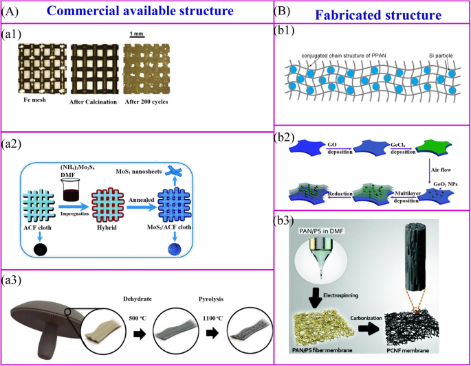
市售结构的热处理 (a ) 和装配式结构 (b )。 a1 金属氧化物纳米粒子可以通过简单的热氧化过程在金属结构的表面获得 [34]。 a2 活性材料可以通过热处理在导电结构的表面合成[35]。 a3 生物质可以被碳化以实现碳结构[32]。 b1 聚合物和活性材料的混合物可以被碳化以实现无粘合剂电极[36]。 b2 层次结构可以通过多个过程获得[37]。 b3 对静电纺丝膜进行热处理可以获得无粘合剂电极[38]
市售的结构用作支撑骨架以固定活性材料。这些材料包括金属网、碳纤维、商业海绵、生物衍生物和商业海绵[39]等(图2a)。金属氧化物纳米粒子可以通过简单的热氧化过程在金属集电器的表面合成[34](图2a1)。无需任何进一步处理,这些集电器可直接用作无粘合剂 LIB 的支撑材料。铁网负载的 Fe2O3 显示出非常高的放电容量,为 1050 mAh g −1 200 个循环后。用活性材料的前体溶液对导电膜进行热处理是一种广泛开发的制造无粘合剂电极的方法(图 2a2)。一个有代表性的例子是在活性炭纤维 (ACF) 布表面涂覆的超薄 MoS2 纳米片可以通过浸入 (NH4)2MoS4 溶液中然后退火来制造。电化学性能表明,放电容量为 971 mAh g -1 在 100 mA g −1 的电流密度下实现 [35]。生物质材料的热处理是制备无粘合剂电极的一种简单方法。 Ozkan 及其同事将波多贝罗蘑菇碳化为无粘合剂的 LIB 阳极(图 2a3)[32]。在高温下,生物质材料的结构可以保持不变,天然存在的杂原子和金属离子可以掺杂在碳材料中,从而提高了电子电导率和容量等电化学性能。
聚合物是构建无粘合剂电极自支撑骨架的主要材料,骨架结构由聚合物及其制备方法决定(图2b)[40]。首先,对于普通聚合物,聚合物-活性材料复合膜在 550°C 下热解可以制备无粘合剂电极(图 2b1)[36]。 Si/SiOx/PAN 复合电极是通过这种方法制备的 [41, 42]。退火后,聚丙烯腈(PAN)可以转化为N掺杂的导电结构,碳网络不仅可以稳定SEI并适应体积变化,还可以为电极提供良好的柔韧性和机械强度。类似地,Si/rGO 电极可以通过将 Si、还原氧化石墨烯 (rGO) 和聚乙烯吡咯烷酮 (PVP) 悬浮液浇注到泡沫镍上,然后进行退火过程来获得 [43]。其次,逐层 (LBL) 工艺是制造复杂结构和纳米材料的一种有吸引力的方法。可以通过将钛箔浸入聚(二烯丙基二甲基氯化铵)(PDDA)溶液、氧化石墨烯(GO)悬浮液、PDDA 溶液和 H3PMo12O40 水溶液中以特定循环,然后在 500°C 下热处理来制造多层电极[44]。这种LBL方法可用于大规模制备无粘合剂电极。这种方法适用于制备介孔锐钛矿TiO2/泡沫镍[45]、MoS2纳米片/ACF和多层GeO2/rGO(图2b2)[37、46]。最后,可以通过将活性材料封装到聚合物中,然后制造成新型纳米结构来制造无粘合剂电极(图 2b3)。可通过静电纺丝和后续热处理合成柔性分层纳米纤维垫。
市售的和制造的结构有许多优点。活性材料涂覆在可商购结构的表面上,而制造的结构用作封装活性材料的容器。与活性材料的封装相反,表面涂层使活性材料和电解质的接触更多。因此,它具有更好的倍率性能,但初始库仑效率较低,循环性能较差。
水热处理
水热法在过去几十年中被广泛应用于不同学科。目前,该技术在机制解释和材料制造方面做出了巨大努力。对于水热过程,金属离子溶解在溶液中,然后在高温高压下形成过饱和溶液。在此过程中,晶体生长发生在衬底的成核点。与热处理制备的聚集颗粒相比,水热法可以在温和的条件下生产出高纯度、均匀、单分散、可控的纳米级材料。精细纳米结构的水热工艺在储能材料领域受到广泛关注。
使用水热法制备无粘合剂电极的整体合成过程类似于图 3a 中描述的过程。首先获得支持材料。如果支撑材料光滑且成核点有限,则活性材料在其表面的沉积将被禁止。一般来说,碳布需要进行酸性或热处理才能变得更亲水。此外,还应加入合适的沉淀剂来调节溶液的pH值,以促进前驱体在基材表面的生长。对获得的材料进行热处理以获得所需的复合材料,同时保持纳米结构。 Hu、Zhang 和同事报告了一种可扩展的制备 ZnxCo3-xO4 纳米立方体/CNF(碳纳米纤维,CNF)的方法。立方体的大小可以通过水热过程中应用的pH值来调整[47]。
<图片>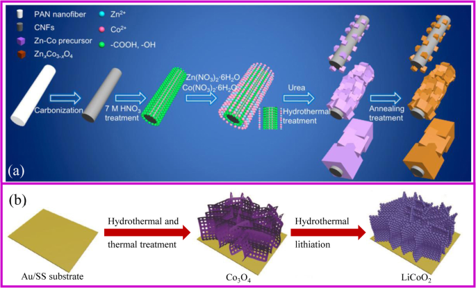
一 ZnCoOx/CNF 复合材料制造方案 [47]。 b 水热法制备阴极[48]
水热法可以制造单组分和多组分[49]。已经开发了许多无粘合剂电极的形态,例如碳纳米管 (CNT) 支架上的 TiO2 纳米棒 [50]、Fe3O4 纳米粒子、NiO 纳米锥、Ni(OH)2 纳米片和在泡沫镍上生长的 Fe3O4/Ni/C 纳米片 [50]。 51,52,53,54]、石墨烯泡沫上的 MnO2 纳米薄片 [55] 和碳纤维上的 FeF3·0.33H2O 花状阵列 [56]。 Li 和同事生长的 NiCo2S4 纳米管阵列显示出独特的 3D 结构,其中 NiCo2S4 纳米管的长度为 5 nm,宽度为 100 nm [57]。通过使用 NiCl2·6H2O 和 CoCl2·6H2O 作为前驱体,可以获得在 3D 石墨烯网络上生长的多孔 NiCo2O4 纳米针 [58]。这些纳米结构均匀分布在导电基材上。因此,这些复合材料不仅促进了电子转移并适应了放电/充电过程中活性材料的体积变化,而且还提高了锂离子电池的高容量、高倍率和循环稳定性等电化学性能。具体而言,Fe3O4 纳米颗粒@Ni 泡沫表现出 543 mA h g −1 的可逆容量 在超过 2000 次循环后,电流密度为 10 C [51]。 NiO阵列@Ni泡沫可以提供969 mAh g −1 的容量 在0.5 C的电流密度下,仍然保持在605.9 mAh g −1 在 10 C [52]。
值得注意的是,水热法是实现正极材料金属氧化物锂化的良好策略。传统的锂化需要将前体与锂盐均匀混合,这很难获得所需的无粘合剂电极。水热锂化是一种溶液法,不需要对前驱体进行处理,因此它是制备无粘合剂正极的有吸引力的方法之一。 2018 年,Xia 等人。通过 Co3O4 前驱体的水热锂化制备了多孔 LiCoO2 无粘合剂阴极,以 Au 涂层不锈钢为基材(图 3b)[48]。该电极显示出优异的倍率和循环性能,容量为 104.6 mA h g −1 10 C倍率下,1000次循环后容量保持率为81.8%。
化学浴沉积
化学浴沉积 (CBD) 是通过化学反应在基材上原位生长活性材料的过程。与水热法相比,这种合成方法易于放大,并且无需使用特殊设备即可使纳米材料在低温常压下生长。此外,CBD和水热法通过类似的机制在基板表面生长材料,因此对基板的要求非常相似。与图 4a 所示的过程相同,通过调节反应的 pH 值和温度,活性材料的前体将成核和生长。例如,通过在酸性 KMnO4 溶液中存在 3D 石墨烯气凝胶制备 3D 石墨烯/MnO2 杂化物 [59]。
<图片>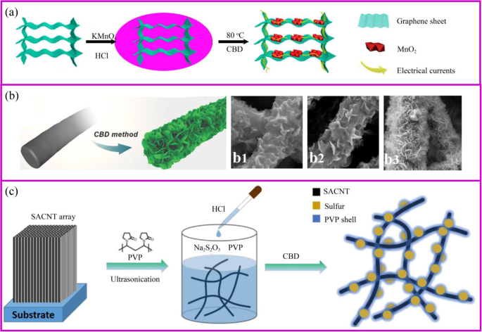
一 3D 石墨烯/MnO2 混合体的制备示意图,以及 3D 石墨烯/MnO2 混合体上的电子转移示意图 [59]。 b 用于制造 CNF@Ni(OH)2 的 CBD 方法 [60]。 b1–3 随着 Ni(NO3)2 溶液浓度增加的不同混合膜。 c PVP@S-SACNT复合材料合成流程示意图[61]
活性材料的形态受支撑材料、反应时间和前体浓度的影响(图 4b)。底物决定了初始成核位点。例如,MnO2 的形态分别是石墨烯和碳纳米管基底上的纳米片和纳米颗粒 [62, 63]。此外,载体材料上活性材料的形态受前体浓度的影响。例如,在低 Ni(NO3)2 浓度下,薄的 Ni(OH)2 纳米片开始在纳米纤维表面形成并垂直生长(图 4b)[60]。然而,随着Ni盐浓度的增加,一层厚厚的Ni(OH)2纳米片逐渐形成,这可能是由于Ni(OH)2快速均匀的成核。因此,载体材料上活性材料的形态可以多种多样,如颗粒[64]、鞘、纳米片[65]和纳米线[66、67]。与水热法制备的电极类似,纳米级材料的多孔导电结构可以为锂离子的快速扩散和电子的快速传输提供连续通道,实现快速锂化/脱锂。
硫是一种非常有前途的正极材料,可以在温和的条件下通过 CBD 合成。硫磺材料基于 Na2S2O3 与酸在室温下水溶液中的简单反应。该过程简单且对环境无害。当应用合适的模板或表面活性剂时,可以获得特殊的纳米硫结构[68]。当导电材料可以吸收 S2O3 2- ,在相间产生大量的硫。由苯基磺化官能团改性的石墨烯允许硫通过原位氧化还原反应均匀沉积 [69]。通过将硫纳米颗粒原位固定到导电网络上来制备无粘合剂的 PVP 封装硫电极(图 4c)。 PVP 是一种具有疏水性烷基链和亲水性酰胺基团的两亲性聚合物,可用作分散剂。当向溶液中加入酸后开始形成硫时,PVP 的疏水性使其优先包覆在 S 表面形成致密层以保护多硫化物溶解[61]。
化学气相沉积
化学气相沉积 (CVD) 是一种化学反应,其中气态物质沉积在热基板的表面上。这种方法可以在催化剂的辅助下在三维结构和纳米线上产生均匀的薄膜。 CVD工艺包括三个步骤:(1)反应气体在热基体表面的扩散和吸收;(2)气体在活性部位反应形成涂层材料;(3)排出热基体产生的气体。通过控制温度、压力、气体比例和类型,可以获得所需的涂层材料。
CVD法可以直接生长活性材料。 Tay 及其同事报道了一个与 CVD 工艺相对应的令人印象深刻的例子 [70]。 3D泡沫镍/碳纳米管复合材料以泡沫镍为基材,乙醇为前驱体和碳源合成。获得的碳纳米管用作沉积 NiO 纳米片生长的基底。无定形 FeVO4 纳米片阵列可以直接在以 VCl3 为前驱体的柔性不锈钢基板上生长。它可以提供601 mAh g −1 的可逆容量 和 453 mAh g −1 分别在8 C和15 C的高电流密度下[71]。
通过 CVD 制备的表面层也用作电极和电解质之间的保护界面。 Yang等人以乙烯为碳前驱体,通过CVD工艺包覆活性材料,不仅提高了结构的稳定性,而且形成了优良的电子导电网络。具有碳涂层的 Si 纳米线显示出良好的倍率性能 [72, 73]。 2016 年,崔等人。表明通过 CVD 方法制备的具有亲锂材料薄层的多孔材料可以作为促进锂离子均匀沉积的支架 [74]。该材料即使在 3 mA/cm 2 的高电流密度下也表现出稳定的循环性能和很小的过电位 充放电过程中。
CVD方法是制造先进Si材料的主要策略之一。硅是下一代锂离子电池最有前途的负极材料,因为它的比容量最高可达 4200 mAh g −1 和低工作电压[75]。然而,硅遭受巨大的体积变化,导致在循环过程中连续形成固体电解质界面(SEI)、粉化和容量衰减[76]。一般来说,先进的硅材料可以通过对硅颗粒进行后处理或通过还原二氧化硅来制备。 CVD 是通过还原或热解高纯度硅烷或硅烷替代物来制备薄膜或纳米线硅的理想方法。 2008 年,崔等人。使用CVD方法以Au纳米粒子作为催化剂在不锈钢上合成硅纳米线(Si NWs),并成功地将其用作LIBs的阳极[77]。直径约为 89 nm 的硅纳米线可以适应 400% 的体积变化而不开裂。此外,纳米线直接生长在集电器上,所有纳米线都对容量做出积极贡献。由于纳米结构,整个多孔电极具有非常大的比表面积,因此具有极好的离子传导性。纳米线硅材料的理论容量可达4200 mAh g −1 第一次以 C/20 的速度。尽管纳米线的直径在循环过程后从 89 增加到 141 nm,但整体结构保持完整。 Si的生长由催化剂控制。不锈钢还可以作为硅膜形成的催化剂。然而,在集电器上形成硅层会在硅层和集电器之间造成严重的应力。通过控制活性种子,可以在某个步骤干扰 Si 的生长。例如,具有 Au 或 Sn 纳米颗粒的化学稳定的石墨烯或金属 Ge 表面可以作为 Si NWs 生长的种子 [78, 79]。
原子层沉积
原子层沉积 (ALD) 方法是一种气相、自限性和逐层沉积,类似于 CVD。这种方法可以在原子层逐层沉积中产生纳米级和可控的薄膜。因此,该过程应由至少两种不同的前驱气体组成,它们可以相互反应 [80]。在ALD工艺过程中,第一气体被引入管式炉中并与基体反应形成具有活性基团的涂层。在第一种气体完全排出后,引入第二种气体与第一层反应(图 5a)[81]。通过重复这个过程,可以获得不同的涂层。 ALD的镀膜主要受基材、气体前驱体、温度等影响。与传统的薄膜沉积方法相比,ALD可以通过化学反应精确控制整个基材的涂层厚度,涂层不仅是针孔自由、致密、均匀,但即使沉积在复杂的 3D 结构上也能保形。 ALD的这些特点使其成为纳米技术和材料的绝佳选择。
<图片>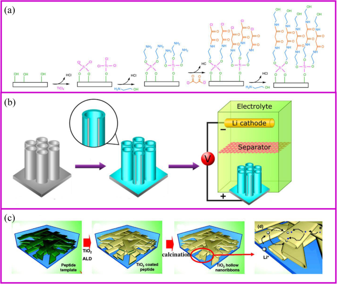
一 ALD 技术机制 [81],以及 b 的两个例子 表面涂层 [82] 和 c 活性材料制备 [83]
ALD 制备的电极通常具有良好的电化学性能。 TiO2 是研究最多的电极材料(图 5b、c)[84]。最近,SnO2 [85]、MoS2 [86] 等被制备并成功用作 LIB 的活性材料(图 5c)[87, 88]。由于ALD是一种气相合成方法,它可以在材料的表面或孔隙内部涂覆一层厚度可控的均匀层。 Kang 及其同事 [83] 证明纳米带作为电极中的活性材料可以使电解质浸入材料内部,从而大大提高锂离子的扩散速率。在模板的帮助下,纳米带的中空空间可以通过 ALD 合成,隧道尺寸的宽度接近 100-200 nm,高度接近 20-50 nm。它允许电解质容易地润湿中空空间。与 100 nm-TiO2 纳米粉末相比,TiO2 纳米级网络的倍率性能在 5 C 下提高了至少五倍。比纳等人。涂有 TiO2 层的多孔电极。发现具有更薄涂层的材料表现出更好的倍率性能。当TiO2层厚度从2增加到7和20 nm时,容量从227减少到214和157 mAh g −1 , 分别[89]。
ALD在电化学存储中最普遍的应用是保护电极的表面稳定性以提高电化学性能[90]。用于 LIB 的 TiO2 纳米管上均匀的 Al2O3 涂层是表面保护最具代表性的例子(图 5a)[82]。 The coating thickness of the Al2O3 layer onto the TiO2 nanotube can be controlled by ALD from 0.2, 1 to 10 nm according to the repeated cycles. The 1 nm coating Al2O3 layer can suppress the SEI formation and undesirable side reactions, which greatly improves the capacity. In addition, Al2O3 as an artificial layer can participate in the formation of SEI with Li–Al–O groups, which are great ionic conductor. Therefore, the Li-ion conductivity in improved and great rate performance can be achieved. Noked et al. demonstrated the 14 nm Al2O3 layer can effectively improve the stability of lithium metal interface by avoiding the reactions with electrolyte, cathode shuttles, etc. [91]. Comparing with the bare lithium metal anode, the ALD-protected anode can significantly improve cycling performance.
Electrical Methods
Electroplating
Electroplating is a versatile technique that functions to improve the surface properties of materials or to prepare nanoscale structures. The deposition mechanism is that in the case of an applied electric field, the ions move to the positive electrode and are reduced on the surface of the substrate to form a film. The thickness of film is controlled by the current density and time. Through post-treatment, the metal film can be oxidized to the corresponding metal oxide.
Template synthesis is the most popular method for preparing nanostructures of various materials using electroplating in LIBs. Chen, Xia, and coworkers obtained porous CoO semisphere arrays using the polystyrene as the template [92]. Yan, Tong, and coworkers demonstrated that CoO can coat on the surface of ZnO nanorod arrays by electroplating method. The ZnO template can be removed by treating the obtained electrode at KOH solution [93].
Electroplated surface layers also serves as a protective interfaces between the electrode and the electrolyte. Cu/TiO2 NT/Ti electrode can be prepared via electroplating Cu on TiO2 NT/Ti film. The prepared materials display a much higher discharge capacity, cycle stability, and Li + diffusion coefficient than bare TiO2NT/Ti electrode [94]. Mulder et al. designed a 3D Ni honeycomb current collector for stable Li metal anode [95]. By controlling the porosity of Ni material with polyethylene glycol as an additive, the Li plating/stripping performance can prolong to 300 and 200 cycles at 0.5 mAh cm −2 and 1.0 mAh cm −2 , respectively, at 1.0 mA cm −2 .
Anodization
Anodization is a well-established technique for modifying a layer on the metal surface. Generally, the metal surface can be thermal treated to form the corresponding oxide protective layer. However, this heating process often carries out at a high temperature, which changes the material structure and properties. Therefore, it is necessary to develop a low temperature method. Anodization refers to a technique in which a metal material is oxidized and precipitated in the electrolyte solution by applying an anode current at room temperature. Anodization is popular because of its controllable structure, economical, and large-area preparation.
李等人。 firstly reported the porous Fe3O4 thin film as anode material cycled about 100 cycles at the 0.1 C [96]. Subsequently, TiO2 [97], NiO [98], WO3 [99], CuCl nanoparticles [100], etc. were prepared and showed decent cyclic stability, good ion and electron conductivity, and enhanced capacity. The NiO@Ni foam can deliver a reversible capacity up to 705.5 mAh g −1 and 548.1 mAh g −1 at a current density of 1 A g −1 and 2 A g −1 , respectively.
Electrophoretic Deposition
Electrophoretic deposition (EPD) has been widely used as a surface coating and film preparation method. The deposition mechanism is that during the process, the charged particles with small sizes (need to disperse into the solution) in a suitable suspension migrate towards an electrode under an applied electric field (Fig. 6a, b). The morphology of the achieved film is significantly influenced by the electrolyte solution [104]. EPD has the advantages of low cost, simplicity, green, and controllable operation [105].

一 Schematic of process for fabrication of binder-free, carbon-free film electrodes [101]. b Schematic fabrication process for the Fe3O4/CNTs/rGO composite electrode [102]. c Schematic illustration of the synthesis route for rGO/active materials/Ni foam [103]
An electrode made by EPD shows better electrochemical performances than slurry-coated electrode. Robinson and coworkers proved that the Co3O4 nanoparticle films formed by EPD showed better adhesion and cycle performance than the electrode prepared by conventional methods (Fig. 6a). The EPD can provide a more effective mixed state between active materials and conductive additives [101]. It is worth noting that carbon nanotubes, graphene, and other carbon materials together with active materials can be deposited onto the current collector, which significantly improves the electron conductivity [106, 107]. Besides, the porous structure formed during the EPD process is crucial to accommodate the volume change during lithium-ion insertion and extraction. Zhao and coworkers demonstrated that the Si nanoparticle electrode prepared through EPD shows better electrochemical performance (Fig. 6b) [102, 108].
EPD is able to deposit surface layers composed of either active or inert materials. These layers serve as protective interfaces between the electrode and the electrolyte. For example, the reduced graphene oxide thin film deposited onto the surface of the electrode to improve the electrical conductivity and to buffer the volume changes during charge/discharge processes (Fig. 6c) [103].
Physical Methods
Electrospinning
Electrospinning is a simple and popular technique to synthesize 1D nanostructures with fiber diameters ranged from tens of nanometers up to micrometers [109]. This preparation is difficult to achieve by the approaches mentioned above. This technique can produce polymers, organic, and inorganic composites with dense, hollow, or porous structures [110], from polymer solutions based on electrostatic forces [111]. An electrospinning unit generally consists of a syringe and a needle, a grounded collector, and a high-voltage supply, as shown in Fig. 7a, b [117]. During the electrospinning process, polymer solutions are loaded in the syringe and move into the needle to form a droplet. When a high voltage is applied between the needle and the collector, the electrostatic force at the surface of droplet would drive it to elongate to form a fiber. Finally, the solid polymer fibers would deposit onto the collector.

The schemes of a single axial and b coaxial electrospinning [111, 112]. c Inorganic fibers [113]. d Inorganic particles encapsulated carbon fibers [114]. e The modification of carbon fibers [115]. f Carbon fiber membrane with nanoparticles [38]. g Highly flexible carbon fiber membrane [116]
The polymer solutions and needle are the key points for the success of fiber fabrication. Polymer solution should reach the minimum viscosity for the formation of homogeneous fiber structure. The solvent of polymer should have a lower evaporation rate, which allows the polymer solidification after leaving the needle. The needle should be designed with coaxial structure to achieve hollow or core-shell fiber structure (Fig. 7b). For the coaxial electrospinning, the core and shell solutions should be adjusted to be immiscible or non-precipitable. Besides, during the electrospinning process, solution flow rates, voltage, temperature, distance from needle to the collector, and diameter of the needle have a huge influence on the fiber structure.
The obtained electrospun membrane needs further treatment to be a binder-free electrode. Carbon, ceramic, or metal nanofibers can be synthesized from the carbonization of electrospun fibers that contain polymer, metal salts, or metal atoms, respectively. Their composites such as metal/C and ceramic/C can be also obtained from their corresponding mixed precursors followed by a one-step or multi-step heat treatment. A wide range of electrospun materials have been investigated for LIBs including metal oxides (e.g., TiO2, Fe2O3, ZnO, NiO, CuO, LiCoO3, Li4Ti5O12, and LiMn2O4) [118, 119], hybrids [120] (e.g., SnOx/C, SiOx/C, Co3O4/C, SnOx/C, TiO2/C) [113, 121,122,123,124,125,126,127,128,129,130], and polymers (e.g., polyvinyl alcohol (PVA), PAN and PVP, poly(vinylidene fluoride-co-hexafluoropropylene) (PVDF-HFP), and polyethylene oxide (PEO)) [131].
Conventional electrospinning generally disperses metal salts and nanoparticles inside the fibers. However, the nanoparticles can adhere to the outside of the fibers as well (Fig. 7c). Lan, Yang, and coworker prepared 3D free-standing spider-web-like membranes with high mass loading of bismuth (Bi) nanoparticle clusters followed by carbonization in nitrogen gas [132]. The 3D Bi/C membrane provides good mechanical properties and stabilizes the Bi nanoparticles up to 200 cycles.
The architecture of fibers can be optimized to accommodate large volume changes and instability of the electrode materials during cycling process. The adjustment of the fiber structure can be started from either inside or outside of the fiber. The internal fiber can be regulated by the polymer solution and post-treatment, while the external fiber structure is controlled by post-treatment. When the polymer solution contains etchable materials, a porous fiber structure can be prepared after carbonization and template etching (Fig. 7d). This porous materials is capable of accommodating higher sulfur and suppressing the polysulfides shuttle effects [114]. The polymer can individually form an active material at the expense of flexibility self-standing property. This disadvantage can be addressed by additives.刘等人。 showed the PAN fibers with an appropriate amount of CNTs can still be self-standing after sulfurization [115]. The sulfur only exists in the form of Li2S2 and Li2S3 rather than polysulfides in the sulfurized PAN. Therefore, it shows ultra-stable cycling performance up to 1000 cycles (Fig. 7e).
Alternatively, the post-treatment of the surface of electrospun fibers is another way to prepare the high-performance binder-free electrode (Fig. 7f) . After carbonization, the three-dimensional conductive network is formed to provide good electronic conductivity. The fiber surface also provides a large number of sites for the growth of active materials with easy access to electrolyte [38]. Another post-treatment is to coat the nanofibers with a protective surface layer. Generally, the nanoparticles spinning out with the polymer solution is inevitably exposed at the surface of the fiber. This part of the material may fall off from fibers during the cycling process, so the surface coating is equivalent to the protection of the fiber [133].
In addition to polymer solution, the needle is also of importance to the fibers design. The core-shell composite nanofiber can be prepared by a dual nozzle coaxial electrospinning setup (Fig. 7g) [116]. This needle can achieve a great core-shell fiber structure. Besides, hollow fibers can be prepared by designing the inner and outer solutions. When the hollow fiber is filled with the active material, there is sufficient space to allow the volume to expand [112].
Vacuum Filtration
The vacuum filtration method is a rapid manufacturing process to assemble different kinds of nanoscale materials into the macroscopic film for various applications. This process is low-cost, rapid, and efficient, which demonstrates a promising strategy for various functional films. 2D materials can be easily assembled into flexible self-standing paper-like materials, which can be directly used as flexible binder-free electrodes in energy storage devices [134, 135]. In general, the active materials are randomly dispersed between the supporting materials. Therefore, high mechanical strength and flexibility are preserved for the papers (Fig. 8) [136, 137].

The scheme of vacuum filtration process [136]
The vacuum filtration features as the following strengths. Firstly, active materials can adhere on the conductive substrate, leading to the improvement of electron conductivity. For example, the electron conductivity of MoS2 can be largely improved; therefore, better rate performance can be obtained [138, 139]. Secondly, the large surface area is in favor of the contact between active materials and lithium ions, which facilitates the transportation of Li-ion. When the active material is added into the 2D material, the interlayer spacing becomes large; thus, the electrolyte can be immersed. The lithium ions are more accessible to the material; thereby, the interface impedance of material is reduced [140]. Thirdly, the effective material utilization is also facilitated by hindering the aggregation of 2D materials [141,142,143]. Lastly, the material agglomerations and electrode instabilities result from the huge volume change of active materials during Li insertion/extraction [144, 145]. Supporting sheets can absorb stress induced by volume expansion, similar to the role of elastic buffer [146, 147].
Different types of nanostructures can be assembled into 2D materials. For example, the nanoparticles, nanotubes, nanosheets, nanorods, etc. can fabricate into the graphene sheets [148]. When CNTs as additive are assembled into the nanosheets, the restacking of the nanosheets can be prevented, and the conductivity of ion and electron can be greatly increased [149]. The electrode chemical properties can be enhanced by coating or mixing active materials on other conductive materials and then assembling into 3D functional materials [150,151,152]. It is mainly attributed to the synergistic effects that 3D structure not only serves as a flexible scaffold for strains/stresses release and volume expansion, but also offers a three-dimensional conductive architecture with open channels for electron transfer and Li-ion diffusion. Besides, pre-protection of active materials is a way to improve material stability. The surface modified anode materials in graphene exhibit high capacities, long cycle-life, and excellent rate performance [153]. The Mn2P2O7-carbon in graphene electrode delivers a capacity of 585 mA h g −1 at a current density of 1000 mA g −1 . When increasing the current density to 5000 mA g −1 , a high capacity of 400 mA h g −1 can be remained even after 2000 cycles [153].
Physical Vapor Deposition
At certain temperature and airflow rate, the elemental vapor can be easily deposited onto the porous supporting materials [154,155,156]. Solid sulfur and red P nanoparticles are the typical materials, which can be deposited into porous carbon materials. The commercialization of sulfur as cathode materials is blocked by several intrinsic problems, including low electronic/ionic conductivity, large volumetric expansion, and shuttle effect of intermediate polysulfides (Li2Sx (4 ≤ x ≤ 8)). Particularly, the shuttle effect of polysulfides results in transport of sulfur from cathode to anode and the reaction with Li metal, which leads to significant capacity loss and safety issues. So far, the design of porous structure is the basic strategy to suppress the polysulfides shuttle effect, and sulfur vapor deposition is an effective way for the fabrication of S/C composite. It is an environmentally friendly, solvent-free method in which the sulfur powder undergoes a physical deposition process with no changes of chemical properties [157]. With proper absorbent in the structure, the shuttle effect of polysulfides can also be fixed. Recently, Yang, Zhang, and coworkers reported Ti3C2Tx paper is a good host for sulfur deposition (Fig. 9a). This Ti3C2Tx paper shows no cracks after 25 convexly and concavely bending cycles (Fig. 9b, c) [158]. Yu and coworkers [159] demonstrated porous carbon fibers encapsulated with red P shows high capacity of 2030 mAh g −1 at 0.1 C rate after 100 cycles. It is worth noting that physical vapor deposition (PVD) is only one of the procedures of immobilizing S or P onto carbon materials. Therefore, the most important research direction is how to design a porous conductive matrix.

一 The scheme of fabrication of robust, freestanding, and conductive Ti3C2Tx/S paper. Photographs of freestanding Ti3C2Tx/S paper when bending b convexly and c concavely, showing good mechanical flexibility similar to that of the pure Ti3C2Tx paper [158]
Application in Flexible Batteries
Flexible devices, such as wearable displays, sensors, sportswear, mobile communication devices, rollup displays, and so on, are one of the important directions for intelligent and smart world [160]. The development of these new devices requires the power of a flexible battery system [161,162,163]. However, current advanced pouch and 18,650 cells cannot be used on flexible devices due to the rigid material properties. Each component of the flexible battery, such as electrodes, separator, and solid electrolyte, must be flexible (Fig. 10a) [164]. The conventional electrode is generally adhered to the metal foil by a coating method to physically bond the active material and the conductive agent. During repeated bending and folding, the active material separates from the current collector, ending up with deactivation. For example, the Li4Ti5O12 (LTO)-based electrode folded about 100 cycles would present the detachment of LTO from Al foil. The impedance of the electrode increases from the first fold, and the higher the active material loading, the faster the impedance increases (Fig. 10b). At the same time, the pouch cell bending 30° results in serious capacity fade (Fig. 10c).

一 Assembly and bending tests of flexible batteries with flexible electrodes [164]. b Electrical resistance change with folding cycles [165]. c Capacity retention of folded cells at different angles at 1 C [165]
There are many strategies to fabricate flexible electrodes. Song et al. reported that coating LTO particles and Ag nano wires onto the polyethylene terephthalate (PET) web can greatly improve the electrode flexibility and stability. The electrical resistance of Ag@LTO@PET electrode does not change during 1000 folding cycles (Fig. 10b). Pouch-type Ag@LTO@PET-based half cells showed great cycling performance with little capacity decay when the electrode was bent at any angle (Fig. 11c) [165]. The most mature method is to fix the active material on a flexible substrate. As described in the “Introduction” section, the direct growth of the active material on the conductive substrate can improve battery energy density and rate performance. Herein, we take the carbon cloth and carbon materials as the example to show the application of binder-free electrodes in flexible devices.

一 Schematic illustration for the structural features of the flexible SnO2 nanosheets on flexible carbon cloth electrode during the folding (I), the rolling (II), and twisting (III) tests. b Current-time curves of the composite samples at various bending angles of the 1st and 200th cycles, and the inset images show the corresponding bending angles for measurement and photographs [166]
Most carbon materials cannot be used in flexible electronics. For example, a binder-free electrode based on graphite paper can only maintain 25 cycles in a bent state [167]. Comparing with other carbon materials, carbon cloth with excellent flexibility and electrical conductivity is one of the most promising materials for the flexible battery application. Even after the surface modification of inorganic materials, carbon cloth still shows excellent flexibility. As shown in Fig. 11a, there are no apparent changes of the electrode after bending, rolling, twisting, folding, and crumpling tests. After the mechanical test, the active materials on the carbon cloth can maintain structural integrity. Also, after 200 bending cycles, the current value slightly decreases from 17.3 to 16.8 mA, which demonstrates great stability (Fig. 11b) [166].
It is particularly difficult to synthesize flexible carbon materials. For example, the PAN film becomes much more brittle and fracture after carbonization, which is difficult to use in flexible batteries. The ideal carbon material, like the clothes we wear, bending and folding many times can still remain intact. The flexibility of the material can be greatly improved through reasonable design such as the addition of functional additives.王等人。 reported that the carbonized PAN film with SiO2 filler can fully recover to its original state after repeated rolling or folding process [114]. When assembled into the pouch cell, it can withstand at different bending angles up to 180°. Yu et al. demonstrated that Zn(CH3COO)2 assists the uniform carbonization of PAN, which relieved the stress concentration [130]. The film obtained by this method can return to the initial state after folding four times (Fig. 12a). When assembled into the pouch cell, it can light the LED at any folding angle. When the pouch cell is disassembled, the binder-free electrode remains intact while the slurry-based electrode is completely destroyed (Fig. 12b–e).

一 Digital photographs of Zn(CH3COO)2-PAN film, which can be folded four times. LED lighting tests of a full battery when b flat, c folded once, and d folded twice;和 e digital photographs of the electrode after the LED lighting test [130]
Conclusions
In conclusion, recent research progress on the preparation of binder-free electrodes for LIBs has been summarized. The fabrication methods focus on the chemical, physical, and electrical treatment, such as thermal treatment, hydrothermal treatment, CBD, ALD, CVD; vacuum filtration, electrospinning; and electrophoretic deposition, anodization, electrodeposition. Thermal treatment is the most commonly used chemical method to carbonize polymer for free-standing structure or decompose of the precursor of metallic oxide. The hydrothermal and CBD methods are very attractive due to accurate control of the size and morphology of nanomaterials. CBD and hydrothermal methods present in situ growth of active materials on the substrate through a chemical reaction. CVD is defined as the deposition of a gas carrier on a heated surface by a chemical reaction, while the ALD technique is a vapor phase chemical deposition process that is capable of producing high-quality nanoscale thin films in an atomic layer-by-layer manner. The vacuum filtration and electrospinning are the representative physical methods. The former is a physical manufacturing process to assemble different materials like nanoplatelets and nanoparticles into the macroscopic film. The latter can produce 1D nanoscale materials with fiber diameters ranged from tens of nanometers up to micrometers. The electrical method is a widely used technique to make coatings and thin films. However, it is not often used to prepare binder-free electrode. Among these methods, CVD and CBD are excellent ways to prepare silicon-based and sulfur-based materials, respectively.
The binder-free electrode shows better electrochemical performances than the traditional slurry system. The binder-free electrode can improve ionic and electronic transportation, cycling performance, and energy density of the electrodes. In addition, nanoscale materials are uniformly anchored on the supporting materials, which can effectively prevent the agglomeration of nanoparticles and mitigate the volumetric expansion during the repeated cycling process.
The conductive matrix plays a crucial role in the electrochemical properties and performances of the binder-free electrode. The ultra-flexible film has great potential to make a big breakthrough in the field of wearable and flexible devices. However, existing substrates are still unable to meet the requirements. The flexible device requires the binder-free electrode to bend and fold for numerous times with no damage and no separation from the substrate. According to current research process, ultra-flexible and ultra-stable carbon materials become the most promising candidate for next-generation flexible binder-free electrode.
Despite the difficulties, the future is expected. The uniform and large-scale growth of the active material on the conductive substrate is one of the necessary conditions for practical application. Fortunately, it is now possible to achieve. Practical applications need to consider the basic properties of the electrode in the battery, such as the initial Coulombic efficiency and voltage profiles. Therefore, the active materials for both anodes and cathodes should be carefully selected. For example, Si, Sn, or carbon materials serve as promising candidates for anode materials while the cathode materials may be selected from S matching with Li metal, or the existing Li metal oxides. In addition, flexible batteries can be achieved with all of flexible components, such as electrodes, separators, and electrolytes. Although these aspects have been studied for a long time, breakthrough is needed to facilitate the research progress.
数据和材料的可用性
All data are fully available without restriction.
缩写
- LIB:
-
Lithium-ion batteries
- PVDF:
-
聚偏二氟乙烯
- ACF:
-
Active carbon fiber
- PAN:
-
Polyacrylonitrile
- rGO:
-
还原氧化石墨烯
- PVP:
-
Polyvinylpyrrolidone
- LBL:
-
Layer-by-layer
- 开始:
-
氧化石墨烯
- PDDA:
-
Poly (diallyldimethylammonium chloride)
- CNT:
-
碳纳米管
- CBD:
-
Chemical bath deposition
- CVD:
-
Chemical vapor deposition
- SEI:
-
Solid electrolyte interface
- Si NWs:
-
Silicon nanowires
- ALD:
-
原子层沉积
- EPD:
-
Electrophoretic deposition
- PVA:
-
Polyvinyl alcohol
- PVDF-HFP:
-
Poly(vinylidene fluoride-co-hexafluoropropylene)
- PEO:
-
Polyethylene oxide
- Bi:
-
Bismuth
- PVD:
-
Physical vapor deposition
- LTO:
-
Li4Ti5O12
- PET:
-
Polyethylene terephthalate
纳米材料
- 钛在能源材料中的应用
- 13种耐火材料及其应用
- 材料:汽车用玻璃和碳纤维增强聚丙烯
- 重吸收抑制的 II 型/I 型 ZnSe/CdS/ZnS 核/壳量子点的合成及其在免疫吸附测定中的应用
- 轻松合成锚定在 MWNT 上的 SiO2@C 纳米粒子作为锂离子电池的高性能阳极材料
- 锂离子电池用Cr3+和F-复合掺杂LiNi0.5Mn1.5O4正极材料的合成及电化学性能
- PPy 包覆的 MnO2 混合微材料的制备及其作为锂离子电池阳极的改进循环性能
- 石墨烯/WO3 和石墨烯/CeO x 结构作为超级电容器应用电极的评估
- Co3O4 纳米线的环境友好和简便合成及其与石墨烯在锂离子电池中的有前景的应用
- 高压PCB材料和设计
- 各种能源及其例子
- 适合您应用的电阻焊电极