

基于用半导体纳米晶体编码的聚电解质微胶囊的下一代治疗诊断剂:开发和功能表征
摘要
聚电解质微胶囊的制备及其作为药物、荧光标记和金属纳米颗粒的载体的用途是设计治疗诊断剂的一种很有前景的方法。半导体量子点 (QD) 的特点是极高的亮度和光稳定性,这使它们成为有吸引力的荧光标记,可用于观察细胞内渗透和此类微胶囊的递送。在这里,我们描述了一种设计、制造和表征聚电解质微胶囊的物理化学和功能特性的方法,该微胶囊用三功能聚乙二醇衍生物核/壳量子点进行编码和稳定。开发的微胶囊通过动态光散射、电泳迁移率、扫描电子显微镜、荧光和共聚焦显微镜方法进行表征,提供有关其尺寸分布、表面电荷、形态和光学特性的准确数据。还测量了 QD 编码微胶囊的荧光寿命,并评估了它们对微胶囊制备后时间的依赖性。确定了用于编码程序的 QD 的最佳含量,以提供编码微胶囊的最佳荧光特性。最后,证明了鼠巨噬细胞对细胞内微胶囊的摄取,从而证实了有效利用已开发的系统进行活细胞成像和微胶囊在活细胞内运输和递送的可视化的可能性。
背景
使用聚电解质微胶囊作为药物和造影剂靶向递送和控制释放的载体,以及作为体外和体内成像的荧光探针,是转化医学和个性化各种人类疾病诊断和治疗方法的一条有前途的研究方向。 1,2,3,4]。
开发结合药物功能和生物标志物成像工具的治疗诊断试剂,允许对各种疾病进行早期诊断,是设计给药系统领域的一项重要任务 [5, 6]。基于聚电解质微胶囊的系统是结合这两种功能的有希望的候选者。它们的制造条件允许将生物活性物质、金属纳米粒子、荧光标记等结合到微胶囊中 [7,8,9]。附加文件 1:图 S1 示意性地显示了基于聚电解质微胶囊的典型治疗诊断剂。
获得聚电解质微胶囊的有效方法之一是将带相反电荷的聚合物层连续施加到球形或其他形状的基材上,然后将其去除 [10, 11]。带相反电荷的聚阳离子和聚阴离子在特定的 pH 值、离子强度和溶液温度以及溶剂极性下的相互作用会导致互聚物复合物以膜或壳的形式涂覆在基材上 [12,13,14]。
上面列出的因素也会影响所得微胶囊的形态,包括它们的孔隙率和形状以及壁的完整性。例如,聚电解质微胶囊环境的离子强度或pH值的增加有利于形成胶囊壁的聚电解质的构象变化或质子化/去质子化。反过来,这会导致其变形和孔隙率增加,甚至达到结构完整性丧失和过渡到“开放”状态的程度,然后释放胶囊的内部内容物和嵌入其壁中的成分。微环境 [15, 16]。这些特性使聚电解质微胶囊成为发挥刺激敏感传递系统作用的良好候选者,并为设计治疗诊断剂提供了良好的基础[2, 17, 18]。
量子点 (QD) 是直径为 2-10 纳米的荧光半导体纳米晶体,其特点是吸收光谱宽,荧光光谱对称窄。这允许从单个辐射源激发具有不同荧光最大值的 QD,从而提供了将其广泛用作荧光团的可能性,特别是用于多路成像 [19, 20]。量子点的高光稳定性和明亮的荧光决定了它们在检测应用中优于标准有机荧光团的优势 [21,22,23,24]。
较早发表的关于荧光聚合物聚电解质微胶囊开发的研究证明了经典有机荧光染料或在水热碳化下原位形成碳点的一种典型方法,并将葡聚糖转化为发光碳纳米颗粒成聚电解质壳,包裹在初级制备的聚电解质微胶囊的聚合物结构中.有机染料截留的方法是基于异硫氰酸荧光素或罗丹明 B、与低分子量葡聚糖或牛血清白蛋白 (BSA) 偶联的四甲基罗丹明染料扩散到由聚电解质形成的膜的多孔结构中,导致荧光染料充电聚电解质微胶囊的整个结构,如内部中空和聚合物膜。在碳点编码微胶囊的情况下,高热处理的必要性改变了微胶囊结构的柔性并使其更加刚性,这在 pH 和离子强度刺激响应治疗诊断系统开发的情况下并非不受欢迎 [25,26,27, 28,29,30]。
在这项研究中,我们描述了用高荧光水溶性量子点编码的聚合物微胶囊制造的所有技术方面,具有显着的胶体稳定性,描述了它们的物理化学和功能特性,并展示了它们在活细胞成像和微胶囊可视化中的应用活细胞内的运输和递送。该数据可能为下一步开发基于多功能功能化微胶囊的治疗诊断试剂铺平道路。
实验
量子点的溶解和表征
最大荧光 λmax 等于 590 nm 的 CdSe/ZnS 核/壳 QD 由 Pavel Samokhvalov 博士(纳米生物工程实验室,国立研究核大学 MEPhI(莫斯科工程物理研究所),莫斯科,俄罗斯)友情提供。
新合成的量子点涂有三辛基氧化膦 (TOPO),不溶于水。通过用 d,l-半胱氨酸代替 TOPO 并随后用 12- 替换 d,l-半胱氨酸来实现它们向水相的转移 含硫醇和羧基端基 HS-(PEG)12-COOH(Thermo Fisher Scientific,美国)的单位 PEG 衍生物,如前所述 [22, 31, 32]。为此,将 QD 样品溶解在 800 μl 氯仿中,然后加入 1200 μl 甲醇,并将混合物离心 5 分钟。该过程重复3次。然后,将 QD 沉淀重新悬浮在 800 μl 氯仿中。将 d,l-半胱氨酸的甲醇溶液加入悬浮液中,QD 与 d,l-半胱氨酸的重量比为 1:0.13,并将混合物以 16,873g 离心 10 分钟(Centrifuge 5418,Eppendorf,美国)。通过以相同速度离心 3 分钟,用甲醇将 QD 沉淀物从过量的 d,l-半胱氨酸中洗掉。 QD 颗粒在 Concentrator Plus 离心浓缩器(Eppendorf,美国)中干燥 2 分钟。将干燥的 QD 悬浮在 650 μl 0.1 M 氢氧化钠中,并在 Elma Sonic P30H 超声浴(Elma Schmidbauer,德国)中超声处理 10 分钟。然后,将溶液以 5509g 离心 10 分钟,上清液通过孔径为 0.22 μm 的 Millipore 过滤器(Merck,德国)过滤。在第一个激子吸收峰波长处用分光光度法测定样品的QD含量。
通过以 1:4.6 的 QD 与 PEG 衍生物摩尔比添加 HS-(PEG)12-COOH 并在 2-8°C 下孵育混合物 24-48 小时来稳定获得的水溶性 QD 样品。
碳酸钙微粒的合成
如别处所述获得碳酸钙微粒[33, 34]。在搅拌的同时,将 15 ml 0.33 M Na2CO3(Sigma-Aldrich,德国)溶液加入 15 ml 0.33 M СаСl2(Sigma-Aldrich,德国)溶液中。将反应混合物在 RCT Basic 磁力搅拌器(IKA,德国)上以 250、500 和 750 rpm 的速率在室温下搅拌 15 至 60 秒。 СаСl2 和 Na2CO3 溶液通过孔径为 0.22 μm 的过滤器初步过滤。
之后,停止搅拌,将反应混合物温育 10 分钟。通过在 452g 下交替重悬和离心,用 MilliQ 水洗涤混合物 使用 Centrifuge 5810(Eppendorf,美国)离心 5 分钟。将获得的微粒洗涤四次。最后一次洗涤后,将颗粒在 60°C 的烘箱中干燥 90 分钟。
量子点编码聚电解质微胶囊的制备
使用带相反电荷的聚合物 [31, 35] 和羧化水溶性量子点逐层沉积到制备的碳酸钙微粒上的改进技术,用量子点对微粒进行编码,该微粒充当基质。聚电解质层由聚合物对组成:Mw ≈ 15,000 Da(Sigma-Aldrich,美国)的聚阳离子聚(烯丙胺盐酸盐)(PAH)和 Mw ≈ 70,000 Da( Sigma-Aldrich,美国)。
这些层按以下顺序应用:СаСО3/PAH/PSS/PAH/PSS/PAH/QD-S-(PEG)12-COOH/PAH/PSS/PAH/PSS/PAH/PSS。
将干燥的微粒样品重新悬浮在 0.5 毫升 MilliQ 水中,并在超声波浴中超声处理 10 分钟。将在 0.5 M NaCl 中的 2 mg/ml PAH 溶液的 0.5 ml 等分试样添加到含有 3.7 × 10 8 的悬浮液中 MilliQ 水中的碳酸钙微粒。将悬浮液在超声波浴中超声处理 60 秒,然后在搅拌下孵育 20 分钟。之后,通过以 1054g 离心将微粒悬浮液中的过量聚合物洗掉 5 分钟,然后重悬在 MilliQ 水中。聚阳离子分层后碳酸钙微粒的洗涤重复3次。为了施加下一层(聚阴离子),将微粒预先重新悬浮在 0.5 ml MilliQ 水中;将悬浮液与 0.5 毫升 2 毫克/毫升 PSS 的 0.5 M NaCl 溶液混合,在超声波浴中超声处理 60 秒,搅拌孵育 20 分钟,然后如上所述洗涤多余的聚合物。
在编码之前,将五个聚电解质层(由 PAH 组成的外层)施加到碳酸钙颗粒上。将 0.10 至 2.24mg 的 QD 添加到微粒的悬浮液中。将混合物在搅拌下孵育 80 分钟,然后如上所述通过离心洗涤 3 次。之后,连续施加带相反电荷的聚合物层。编码的微粒在+ 4°C下避光保存。
为了获得 QD 编码的聚电解质微胶囊,从微粒中去除碳酸钙核。为此,离心后,将 QD 编码的微粒沉淀重新悬浮在 2 ml 0.2 M 乙二胺四乙酸二钠 (EDTA) (pH 6.5) 中,并将悬浮液孵育 15 分钟。为了保证碳酸钙核心的溶解,我们将这个过程再重复了两次,每次在以 2152g /i> .然后,通过在 MilliQ 水中重新悬浮并在上述条件下离心,将 QD 编码的微胶囊悬浮液用过量的 EDTA 洗涤四次。所得聚电解质微胶囊在+ 4°C下避光保存。
在研究 QD 编码的聚电解质微胶囊与细胞的相互作用时,我们用 BSA(热休克级分,无蛋白酶,低内毒素,适用于细胞培养,pH 7,≥ 98%;Sigma-Aldrich,美国)修饰了微胶囊表面.简而言之,具有聚阳离子上层的编码微粒另外用Mw ≈ 15,000 Da(Sigma-Aldrich,USA)的聚阴离子聚丙烯酸(PAA)包被,并如上所述去除核心。最后一次洗涤后,将微胶囊分散在含有 1% BSA 的 50 mM 磷酸盐缓冲溶液 (pH 7.4) 中,并在 + 4°C 下避光孵育。使用前,用 50 mM 磷酸盐缓冲液 (pH 7.4) 将微胶囊中的过量 BSA 洗掉。
用量子点编码的量子点、微粒和聚电解质微胶囊的表征
规模和费用研究
通过动态光散射法测定溶解的量子点、包覆有聚合物壳的量子点编码微粒和量子点编码聚电解质微胶囊的流体动力学直径;通过 Zetasizer NanoZS (Malvern, UK) 使用多普勒效应从它们的电泳迁移率估计表面电荷。
荧光分析
在荧光最大值的波长下测量溶解的量子点、涂有聚合物壳的量子点编码微粒和量子点编码聚电解质微胶囊的荧光寿命(荧光衰减动力学)。 YAG 的二次谐波:Nd 3+ 使用脉冲长度为 350 ps 和脉冲频率为 50 Hz 的激光作为激发源。该信号由与 DPO 3054 示波器(泰克,美国)连接的光电倍增管检测器检测,时间分辨率为 2 ns。在测量过程中,通过 MIXcontrol eco 磁力搅拌器(2mag,德国)永久搅拌 QD 编码的微粒和微胶囊的悬浮液,以防止样品沉淀。
编码效率估计
在将 QD 应用(吸附)到微粒表面后,从上清液的 QD 含量估计编码效率。吸附在微粒表面的量子点数量 (\( {Q}_{{\mathrm{QD}}_{\mathrm{abs}}} \)) 计算为
$$ {Q}_{{\mathrm{QD}}_{\mathrm{abs}}}={Q}_{{\mathrm{QD}}_0}-{Q}_{{\mathrm{QD} }_i}, $$其中 \( {Q}_{{\mathrm{QD}}_0} \) 是用于编码的等分试样中 QD 的初始数量,并且 \( {Q}_{{\mathrm{QD}}_i} \ ) 是 i 上清液中 QD 的数量 第一个样本。
使用Infinite 200 PRO多模式读板机(Tecan,Switzerland)通过分光光度法测定样品的QD含量。
扫描电子显微镜
使用配备肖特基阴极的 JSM-7001F 扫描电子显微镜(JEOL,日本)获得碳酸钙微粒的电子显微照片。将干燥的微粒粉末涂在导电碳胶带上,以平均 50、20 pA 束流和 15-30 kV 加速电压进行扫描。
为了获得涂有聚电解质层的微粒的显微照片,一滴含有 ~ 10 6 的稀释微粒悬浮液 将每 0.5ml 的微粒置于初步纯化的硅基材上并在室温下干燥。所得样品以平均 50,束流 20 pA,加速电压 3-30 kV 扫描。
荧光和共聚焦显微镜
使用配备德州红荧光发射滤光片的 Carl Zeiss Axio Scope A1 显微镜(Carl Zeiss,德国),通过荧光显微镜分析 QD 编码微粒的形态和尺寸分布;使用 20% 甘油水溶液作为玻片封固介质。
还使用配备激发 405、458、476、488、496、514、561 和 633 nm 激光器和 Leica LAS 的 Leica TCS SP5 共聚焦激光扫描显微镜(Leica Microsystems,德国)研究 QD 编码微胶囊的样品AF 软件版本 2.7.3.9723。使用 Leica HCX PL APO CS 63×/1.20 CORR WATER 物镜在 488 nm 激发波长下进行分析,并设置覆盖 555-620 nm 发射范围的收集滤光片。 20% 的甘油在 PBS 缓冲液 pH 7.4 中的溶液用作玻片封固介质。 Image J 1.51 s软件(美国)用于图像分析和处理。
活细胞体外摄取量子点编码的聚电解质微胶囊
将永生化的小鼠肺泡巨噬细胞系 MH-S(ATCC,美国)维持在补充有 10% FCS、0.05 mM 2-巯基乙醇和 2.06 mM 谷氨酰胺的 RPMI 培养基中,在 5% CO2 和 37 °C 的加湿气氛中。 MH-S细胞培养至3×10 6 35-mm μ 盘和 1.2×10 6 中的细胞 将涂有 BSA 的 QD 编码的聚电解质微胶囊添加到每个 μ 皿中。将细胞分别在 37°C 和 5% CO 2 下进一步培养 4 小时和 24 小时。然后,在 30 分钟内使用 DRAQ5 荧光探针(ex/em 波长 646/697 nm,ThermoFisher,美国)对细胞核进行复染,然后使用 Leica TCS SP5 共聚焦激光扫描显微镜(Leica Microsystems,德国)清洗和分析细胞样品)。使用 HCX PL APO CS 63.0 × 1.30 GLYC/OIL、HCX PL APO λ blue 40.0 × 1.25 OIL 获得 QD 编码的聚电解质微胶囊的细胞摄取图像。 QDs 的荧光在 488 nm 激发,发射在 555-620 nm 处收集,而用 DRAQ5 复染的细胞核的荧光在 633 nm 处激发,发射在 650-750 nm 处收集。
统计分析
使用 MS Office Excel 2007 和 Origin Pro 2015 软件进行统计分析。所有数据均使用至少三个独立实验的结果显示为平均值和标准偏差。
结果与讨论
碳酸钙微粒的合成与表征
使用球形无机晶体,特别是碳酸钙微球粒作为基质取决于它们的生物相容性,以及在不使用对生命系统具有腐蚀性的溶剂的情况下在聚电解质微胶囊的形成过程中将其去除的可能性。碳酸钙微粒本身也可用作缓释或缓释药物递送系统,作为装载药物和控制药物释放到微环境中的基质,即它们在递送系统中具有多种潜在用途[36,37] ,38,39,40,41,42,43,44,45,46]。
决定微晶大小和形状的关键因素是搅拌的速度和持续时间以及反应混合物的孵育时间 [33, 41]。我们已经通过实验确定了获得具有最佳尺寸分布的碳酸钙微球粒的条件。已发现单个 CaCO3 微粒具有几乎规则的圆形形状。附加文件 1:图 S2 显示了在不同搅拌速率下获得的碳酸钙微粒的尺寸分布。从这些数据可以看出,颗粒的尺寸不均匀性随着搅拌速率的增加而增加。如果搅拌速度为 250 rpm,则获得的颗粒尺寸范围为 4.0 至 6.0 微米。在这种情况下,样品中的所有微粒都是独立的,它们的尺寸分布接近正常(附加文件 1:图 S2a)。然而,如果混合物以 500 rpm 搅拌,我们观察到形状不规则的颗粒,这些颗粒是较小颗粒的聚集体,单个颗粒的平均尺寸从 2.7 到 5.6 微米不等(附加文件 1:图 S2b)。在 750 rpm 的搅拌速度下,粒度的分散增加。该样品还包含不规则形状的聚集体,单个微粒的平均尺寸在 3.8 到 5.7 微米之间(附加文件 1:图 S2c)。
因此,以 250 rpm 的速度搅拌反应混合物可以获得具有最佳尺寸分布和几乎规则形状的颗粒并防止颗粒聚集。因此,我们估计了在此搅拌速率下搅拌持续时间对微粒尺寸分布的影响(附加文件 1:图 S3)。与搅拌 30 秒相比,搅拌反应混合物 15 秒会产生更多的较大颗粒。将搅拌持续时间增加到 60 秒具有类似的效果。也就是说,在前一种情况下(附加文件 1:图 S3a)搅拌持续时间不足,而在后一种情况下(附加文件 1:图 S3c)搅拌持续时间过长。因此,我们认为250 rpm的速度和30 s的持续时间是最佳搅拌条件。
根据扫描电子显微镜 (SEM) 数据,碳酸钙微粒的表面是不均匀的,以孔隙度为特征(图 1a)。在× 40,000 的放大倍数下,可以看到微粒依次由较小的亚微米颗粒形成(图 1b)。因此,获得的微粒具有多孔结构和代表的基质,它们不仅适合作为基材,而且本身也可以用作递送系统,并且由于它们特殊的表面结构可以很容易地用作逐层的基质聚合物沉积。
<图片>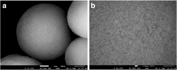
碳酸钙微粒的扫描电子显微照片 (a ) 和它们在更高放大倍数下的表面 (b )
量子点编码聚电解质微胶囊的制备和表征
制备的水溶性量子点的特点是吸收光谱宽,荧光光谱窄,最大发射波长为 590 nm(图 2)。这些 QD 样品的流体动力学直径范围为 23.96 至 28.2 nm。附加文件 1:图 S4 显示了用 HS-(PEG)12-COOH 稳定的 QD 的尺寸分布。用 HS-(PEG)12-COOH 修饰 QD 表面确保了 QD 在水相中的稳定性,以及表面负电荷足以在编码过程中有效吸附带正电荷的聚电解质层之间的 QD [22, 47]。
<图片>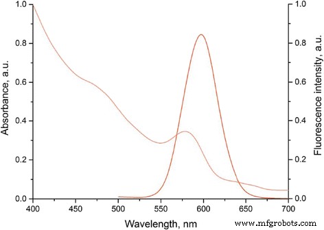
HS−(PEG)12−COOH配体增溶的CdSe/ZnS核壳量子点的光学特性
在聚电解质层和 QD 的每个沉积步骤期间测量的碳酸钙微粒样品的表面电荷值(表 1)证实了原始基质的表面电荷、溶解的 QD 以及每次聚合物沉积后的表面再充电足以保证后续各层的有效吸收。
合成碳酸钙微粒的固有表面电荷和多孔表面结构使它们能够用作带相反电荷的聚电解质和 QD 沉积的基质(图 3)。 PAH 和 PSS 聚合物在 QD 编码的聚电解质聚合物微胶囊中的应用取决于它们的生物相容性和无毒以及非生物降解性,这另外有助于将 QD 保留在壳内。聚-l-精氨酸、聚-l-赖氨酸、壳聚糖、海藻酸钠盐和硫酸右旋糖酐的生物降解性也广泛用于聚电解质微胶囊的形成,将诱导 QD 扩散出聚合物膜,这将导致减少微粒的荧光特性 [3, 11, 39, 48,49,50,51,52]。本研究中使用的 PAH 聚阳离子和 PSS 聚阴离子分别含有胺和硫酸根,确保聚合物层之间的静电相互作用,从而形成聚合物间复合物 [16, 25, 36, 37]。第一聚合物层的选择取决于合成的碳酸钙微粒的表面电荷值。
<图片>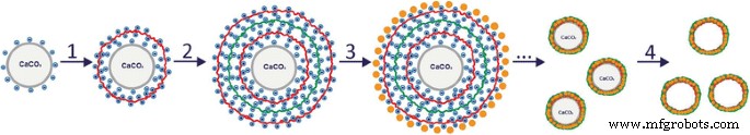
用量子点编码的微胶囊的制备过程:在基质表面分别形成聚阳离子 (1) 和聚阴离子 (2)、PAH 和 PSS 聚电解质层;用量子点和进一步的逐层聚合物沉积对所得微粒进行编码 (3);去除碳酸钙核(4)
图 4 显示了基材表面上聚合物壳形成阶段的 SEM 图像。从显微照片中可以看出,微粒包含一个碳酸钙颗粒核和一个壳,随着吸附聚合物层数的增加,壳变得更加明显。涂有聚电解质层的微粒表面遵循具有其特征均匀性的基材的形状,这表明它也是多孔的(图 4a、b)[44]。随着聚合物壳变厚,微粒表面变得更加平整和光滑(图 4c、d)。
<图片>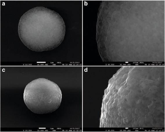
应用四种 (a , b ) 和十个 (c , d ) 聚电解质层
制备 QD 编码的聚电解质微胶囊的最后一步包括去除碳酸钙核心和形成微胶囊的最终结构。为了溶解由碳酸钙颗粒组成的基质,用 EDTA 洗涤微粒。使用 EDTA 主要是因为它在与二价金属盐(包括钙)相互作用时形成水溶性络合物,并且其低分子量确保了 EDTA 聚电解质壳的渗透性及其与 Ca 2+ .这导致聚电解质颗粒的核溶解并形成中空结构[45, 46]。
在我们的研究中获得的 QD 编码的微粒和聚电解质微胶囊具有球形或接近球形的形状,尺寸为 3.8 至 6.5 μm(图 5)。荧光模式下微粒和微胶囊的形态和结构分析表明聚电解质微胶囊内有空腔,与微粒相比,它们具有更高的透明度(图 5b)。这表明用 EDTA 溶解岩心的过程是有效的。共聚焦显微镜数据还显示了所获得的荧光聚电解质微胶囊的中空结构(图 6)。这些微胶囊可以区分为单个颗粒(图 6a,b),由于其表面被 BSA 涂层修饰,可以表征为具有粗糙表面的球形颗粒。
<图片>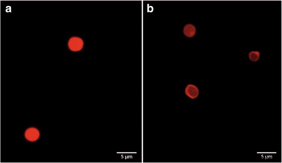
涂有聚电解质并用量子点编码的碳酸钙微粒的荧光显微镜图像(a ) 和从中获得的聚电解质微胶囊 (b )
<图片>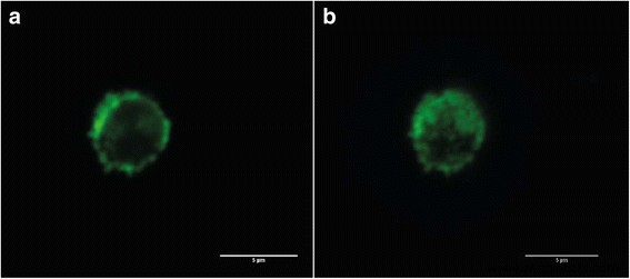
用量子点编码并涂有 BSA 的聚电解质微胶囊的共聚焦显微镜图像:微胶囊的横截面 (a );单个聚电解质微胶囊的 3D 投影 (b )
编码效率估计
编码效率通过吸附在微粒带正电荷的聚合物表面上的 QD 的量来估计。用于微粒编码的原始溶液和微粒与 QD 溶液孵育前后上清液中量子点数量的估计表明,结合到微粒表面的量子点数量随着反应混合物中量子点含量的增加而线性增加。 0.36 至 2.241 毫克(图 7a)。溶液中量子点数量的进一步增加导致吸附的量子点数量减少。这可能是由于微粒表面上由 PAH 的胺基团确定的正电荷密度不足造成的,因为量子点数量过多,导致表面饱和。 Apparently, the QDs were adsorbed more efficiently if their amount was smaller than 2.241 mg owing to sterically favorable conditions and less interference with one another’s attachment. The pattern of the dependence of the encoding efficiency on the QD content of the solution used for the encoding agrees with our earlier data [22].

Estimation of the efficiency of encoding of microparticles with different amounts of quantum dots (a ) and their fluorescence characteristics (b )。 Asterisk indicates significant difference of QD-encoded microbeads from the QD-encoded microcapsules (p < 0.05)
Estimation of the optical characteristics of the obtained polyelectrolyte microcapsules is an essential stage of the assessment of encoding efficiency. Its results show how suitable the given technique is for fabrication of imaging agents based on QD-encoded polyelectrolyte microcapsules.
Figure 7b shows the fluorescence intensities of the microparticles and microcapsules measured as the mean normalized intensity of gray color as dependent on the amount of QDs used for encoding them. As seen from the figure, the fluorescence intensity of the encoded microparticles was higher than that of the microcapsules obtained from them. At the same time, the microcapsules encoded with different amounts of QDs did not differ significantly from one another in fluorescence intensity (p > 0.05). Despite some decrease in the fluorescence intensity of the microcapsules, their encoding with the amount of QDs indicated above ensures a contrast sufficient for effective imaging.
Quantum Dot Fluorescence Lifetime within Encoded Polyelectrolyte Microcapsules
As noted above, the fluorescence intensity of the polyelectrolyte microcapsules was decreased compared to the microparticles used for their fabrication and encoded with the same QDs. Therefore, we have estimated the fluorescence lifetimes of both the original QDs and the same QDs embedded in the microparticles or the polymeric walls of the microcapsules.
The QD fluorescence kinetic curves (Fig. 8) are characterized by monoexponential dependence of fluorescent intensity on time according to the following equation:
$$ I(t)={A}_1\bullet {e}^{-x/{t}_1}, $$
Fluorescence lifetimes of the solubilized CdSe/ZnS quantum dots with a fluorescence peak at 590 nm incorporated in the fabricated microparticles and microcapsules
其中我 (t ) is the intensity of QD fluorescence in response to excitation pulses and A 1, х , and t 1 are parameters describing the change in the intensity with time.
We determined the fluorescence lifetime for each sample (Table 2). The original solubilized QDs had the longest fluorescence lifetime; it was decreased after the QDs were adsorbed onto the microparticles and incorporated into the structure of the polymer shell. This may have resulted from interaction between the QDs and PAH, as we found earlier [22]. In the case of microcapsules, the QD fluorescence lifetime tended to further decrease compared to the QDs within the microparticles from which the microcapsules were fabricated. A possible cause of this decrease was a technological factor entailed in the fabrication of microcapsules, namely, the dissolution of the core and the related increase in the necessary number of washings.
It should be noted, that the fluorescence lifetime also tended to decrease with time after the microcapsule fabrication. However, since 48 h after the microcapsule fabrication, further changes in the mean fluorescence lifetime were insignificant. The fluorescence decay was apparently caused by a decrease in the fluorescence quantum yield of QD embedded in the shells of the capsules. This effect is likely to have resulted from the change in the distribution of the electron potential and the geometric rearrangement of QDs in the inner layers of the polymer shell after the core removal that increased the probability of nonradiative recombination due to the charge transfer to between neighboring QDs or between QDs and polymer molecules [22].
Interaction of Quantum Dot- Encoded Polyelectrolyte Microcapsules with Phagocytic Cells In Vitro
We used confocal microscopy to analyze the interaction of QD-encoded polyelectrolyte microcapsules with live phagocytic cells, their uptake by cells, and the possibility of cell labeling. The murine alveolar macrophage (MH-S) cells were used as a model, because of the capability of these cells to phagocytize xenogenic objects.
The MH-S cells were treated with approximately 1.2×10 6 of QD-encoded microcapsules by short-term (4 h) or long-term (24 h) incubations. We observed signs of primary uptake of the microcapsules in both cases:after the short- and (Fig. 9a–d) long-term incubation (Fig. 9e–h). Polyelectrolyte microcapsules or their conglomerates could be seen in green color. The microcapsules could be clearly distinguished both in the external environment of cells and inside the MH-S cells that could be evidenced by the distance between the microcapsules and nuclei of the MH-S cells which were stained by far-red DNA stain DRAQ5 and can be seen as red spherical shaped objects at all the microphotographs. As individual microcapsules and as their conglomerates were detected to undergo the uptake process. The fact that microcapsules were located in internal cell environment or at least attached to the surface of the macrophages is confirmed by clearly distinguished short distances between the nuclei and the polyelectrolyte microcapsules (Fig. 9b, d, g, h). In Fig. 9g, residually stained boundaries of the macrophage cytoplasmic membranes are distinctly seen, which indicates effective uptake, and well-discernible microcapsules are easy to detect to be attached on their surface either within the cells.

Confocal images of the MH-S cells treated with the QD-encoded polyelectrolyte microcapsules coated with BSA. The upper row shows the images of the samples after 4 h of short-term incubation; the microcapsules are shown by white arrows (a –d )。 The lower row demonstrates the images of the samples after 24 h of long-term incubation; the microcapsules are shown by white arrows (e –h )。 The nuclei of the macrophages were counterstained with far-red DNA stain DRAQ5
During the short-term incubation, single microcapsules were found to be phagocytized by MH-S cells prior to conglomerates of the microparticles. While after long-term incubation (24 h), the amount of the conglomerates of the polyelectrolyte microcapsules undergoing the uptake process and located inside cells or at least attached to the cell surface was more significant than after short-term incubation. Thus, the polyelectrolyte microcapsules obtained in this study used as promising tools for imaging and tracking of live cells.
Conclusions
Our study has demonstrated the feasibility of fabrication of stable QD-encoded polyelectrolyte microcapsules with optimized fluorescence characteristics and a narrow size distribution. The technique for incorporation of water-soluble and stabilized with three-functional polyethylene glycol derivatives core/shell QDs into the polymer wall of the microcapsules and detailed characterization at each stage of experimental procedure ensured efficient fluorescent encoding of microcapsules. The efficient intracellular uptake of developed QD-encoded microcapsules by murine macrophages was demonstrated, thus confirming the possibility of efficient use of developed system for live cell imaging and visualization of microcapsules transportation and delivery within the living cells.
缩写
- EDTA:
-
Disodium ethylenediaminetetraacetat
- PAA:
-
Polyacrylic acid
- PAH:
-
Polycation poly(allylamine hydrochloride)
- PEG:
-
聚乙二醇
- PSS:
-
Polyanion poly(sodium 4-styrenesulfonate)
- QD:
-
量子点
- RPMI medium:
-
Roswell Park Memorial Institute medium
- SEM:
-
扫描电镜
- TOPO:
-
Trioctylphosphine oxide
纳米材料
- 电子和“洞”
- Memfault 与 Alif Semiconductor 合作,为蜂窝物联网和支持 AI 的融合处理器带来下一代设备诊断工具
- 带有基于 Web 的图表的家庭(房间)温度和湿度监视器 – Raspberry Pi
- 半导体纳米晶体有助于生产氢燃料
- 具有高级农业化学活性的智能纳米材料和纳米复合材料
- ZnO 纳米晶体的合成及其在倒置聚合物太阳能电池中的应用
- 不同粒径阿维菌素纳米递送系统的制造、表征和生物活性
- 通过多元醇介导工艺制备和表征 ZnO 纳米夹
- 具有 GeSiSn 纳米岛和应变层的半导体薄膜的形态、结构和光学特性
- 基于生物羟基磷灰石的含锶微晶玻璃复合材料的开发和表征
- Ambarella、Lumentum 和 ON Semiconductor 合作为下一代 AIoT 设备开发基于 AI 处理的 3D 传感
- 下一代工具推动 5G 和边缘发展