

用于对称超级电容器应用的独立柔性 rGO/MWCNT 薄膜的合成
摘要
在此,我们报告了一种新颖、简单且具有成本效益的合成柔性导电 rGO 和 rGO/MWCNT 独立薄膜的方法。通过三电极系统研究了添加多壁碳纳米管对 rGO/多壁碳纳米管纳米复合薄膜电化学性能的影响,在一些强碱水性电解质,如 KOH、LiOH 和 NaOH 中。通过循环伏安法、恒电流充放电和电化学阻抗谱来探测薄膜的超级电容器行为。通过X射线衍射仪、拉曼光谱仪、表面积分析仪、热重分析、场发射扫描电子显微镜和透射电子显微镜进行薄膜的结构和形态研究。用 10 wt% MWCNTs (GP10C) 合成的 rGO/MWCNT 薄膜表现出 200 Fg -1 的高比电容 , 优异的循环稳定性,在 15,000 次长循环测试后保留 92%,弛豫时间常数小(~ 194 ms),扩散系数高(7.8457 × 10 -9 厘米 2 s −1 ) 在 2 M KOH 电解液中。此外,以GP10C作为阳极和阴极,使用2 M KOH作为电解质的对称超级电容器纽扣电池表现出29.4 Whkg -1 的高能量密度 功率密度为 439 Wkg −1 在电流密度 0.1 Ag -1 以及良好的循环稳定性,在 0.3 Ag -1 时初始电容保持率为 85% 10,000 次循环后。 GP10C薄膜在超级电容器中的如此高性能可归因于K + 的大表面积和小水化球半径以及高离子电导率 KOH电解液中的阳离子。
介绍
石墨烯由于其非凡的物理性质,例如非常高的比表面积、优异的导电性、优异的机械柔韧性和异常的热/化学稳定性,自 2004 年被发现后已成为材料科学中研究最多的材料之一 [1, 2,3]。由于上述独特的性质,石墨烯已在纳米电子学[4]、传感[5]、能量存储[6]、太阳能电池[7]和纳米机械装置[8]中找到潜在的应用。然而,单层或双层原始石墨烯的均匀大面积薄膜的制备不仅困难而且昂贵,这阻碍了其在器件制造中的商业化应用。因此,研究人员使用通过亲水性氧化石墨烯 (GO) 的化学和/或热还原得到的还原氧化石墨烯 (rGO) 作为原始石墨烯的替代品。最近,对廉价、可靠、便携和可弯曲电子设备的需求急剧增加 [9]。在这方面,柔性储能设备(超级电容器和锂离子电池)因其集成在柔性电子设备中的目标而成为世界科学界关注的焦点 [10,11,12,13,14,15] .在这方面,可以很容易地转化为自立式纸状形式的材料是非常需要的。因此,在寻找具有良好机械和化学稳定性、优异的导电性和易于转化为大面积薄膜的可弯曲材料时,发现 rGO 是一种非常有前途的候选材料 [16, 17]。有两种方法可以制备独立的 rGO 纸状薄膜或膜。第一种方法涉及在特定滤纸上直接过滤 rGO 分散体 [18, 19]。第二种方法从 GO 粉末的合成开始,并通过使用一些还原剂或通过在惰性/还原环境中退火将 GO 纸还原成 rGO 纸完成 [20,21,22,23]。已经报道了各种技术来合成独立的柔性 rGO 纸。肖等人。通过印刷技术和CO2鼓泡分层法制备rGO纸,所得纸的比电容为55 Fg -1 在 1 Ag −1 [20]。拉斯等人。通过真空过滤GO悬浮液并随后使用氢碘酸(HI)(55%)还原合成rGO纸,并获得~ 80 Fg −1 的比电容(SC) 在 0.5 Ag −1 [21]。李等人。记录了 130 Fg −1 的 SC 在 0.1 Ag −1 对于通过真空过滤 GO 水悬浮液然后通过 Zn 粉末在氨溶液中还原制备的 rGO 纸 [22]。此外,胡等人。通过真空过滤 GO 水分散体和随后的电化学还原合成 rGO 纸。他们报告的 SC 为 106 F cm −3 在 1 mV s −1 扫描速率 [23]。基于文献证据,已经得出的结论是π -π 基面之间的相互作用和强范德华相互作用导致rGO纳米片的重新堆积和聚集,导致rGO纸的表面积减小和电化学性能差[24,25,26,27]。
在这项研究中,我们报告了一种新颖、简便且具有成本效益的方法来合成具有插入在 rGO 片之间的多壁碳纳米管 (MWCNT) 的柔性导电 rGO 薄膜。我们表明,使用适量的 MWCNTs 形成 rGO/MWCNT 纳米复合薄膜可以有效地防止 rGO 纳米片的重新堆叠,从而提高薄膜的电化学性能。使用最佳量的 HI,然后在 250 °C 下在还原环境(3% H2 + 97% N2)下退火 2 h,将 GO/MWCNT 还原为 rGO/MWCNT 薄膜。只需调节用于合成 rGO 和 rGO/MWCNT 薄膜的 GO 分散体的体积,即可轻松控制薄膜的厚度。我们检查了用不同重量百分比(0、5、10 和 15)MWCNT 制造的 rGO/MWCNT 纳米复合柔性薄膜的电化学性能。结果表明,用 10 wt% MWCNTs 合成的 rGO/MWCNT 薄膜表现出优异的比电容为 200 Fg -1 在 0.25 Ag −1 在 2 M KOH 水溶液电解质中,高于之前报道的几个值。所制备的优化自支撑纳米复合薄膜用作阳极和阴极,用于设计具有 29.4 Whkg -1 高能量密度的对称超级电容器装置 稳定性好,在2 M KOH水溶液中10,000 次循环后保持率达85%。
方法
材料
本研究中使用的所有化学品均为分析纯级。收到天然石墨细粉(No. 15553,Riedel-de Haen),MWCNTs(Ctube-120,长度5-20 μm)(CNT Co., Ltd., South Korea)。氢碘酸(57% w/w 水溶液)购自 Alfa Aesar。聚乙烯醇(PVA,MW 89,000~98,000)购自Sigma-Aldrich Company。所有分散体和溶液均在电阻率至少为 18 MΩ cm 的去离子水中制备,温度为 25 °C,取自 Milli-Q 水净化系统(Milli-Q,美国)。
氧化石墨烯的制备
前体材料氧化石墨烯 (GO) 是通过石墨粉在 H2SO4 和 H3PO4 的混合物 (9:1) 中的强化学氧化合成的 [28]。所得产物(GO薄片)在45 °C下真空干燥以除去水分。
MWCNTs 的纯化
在使用前,市售的 MWCNTs(比表面积,40-300 m 2 g −1 ;长度,5-20 mm)在 70% 硝酸溶液中在 90 °C 下回流 24 h。回流后,所得混合物经尼龙膜过滤器(0.45 mm)过滤并用过量去离子水洗涤直至pH变为中性。过滤后的固体在100 °C烘箱中干燥24 h,得到纯化和功能化的MWCNTs。
rGO/MWCNT 柔性独立薄膜的合成与制备
为了合成 rGO/MWCNT 薄膜,将计算量的 GO 薄片通过强烈的超声处理很好地分散在去离子水中,以制备 8 mg/mL 的均匀 GO 分散体。之后,将 0、5、10 和 15 wt% 的 MWCNTs 分别与优化量(20 mL)的 GO 分散体通过~ 1 h 的强声处理混合。将最佳量的 HI 溶液作为还原剂逐滴加入上述 GO-MWCNT 混合物中。将所得混合物倒入直径~ 9.5 cm的培养皿中并在气流中干燥。在乙醇存在的情况下,干燥的 rGO/MWCNT 薄膜可以很容易地从培养皿中去除。因此,将获得的自支撑 rGO/MWCNT 膜用乙醇洗涤数次以去除未反应/残留的 HI 溶液,并再次在空气中在 35 °C 下干燥 12 小时。最后,将风干的自支撑薄膜在还原环境 (3% H2 + 97% N2) 下在 250 °C 下退火 2 小时。整个合成过程的示意图如图 1 所示。制备的具有不同 MWCNT 量(0、5、10 和 15 wt%)的 rGO/MWCNT 薄膜分别称为 GP、GP5C、GP10C 和 GP15C。 <图片>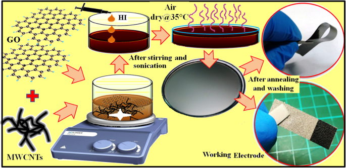
rGO、rGO/CNT纸的合成方案及电极制作工艺
rGO/MWCNT 电极的制造
将一块(1 × 1cm 2 ) 以均匀的 ~ 10 mPa 压力将制成的薄膜涂到泡沫镍上 2 分钟。通过微量天平 (PRECISA XR125M-FR) 以~ 0.1 μg 的精度测量,负载在镍泡沫基材上的活性材料的重量为~ 1.1 mg。合成工艺及电极制作如图1所示。
基于 GP10C 薄膜的对称纽扣电池和固态柔性器件的制造
基于 GP10C 电极的对称超级电容器在使用 2 M KOH 电解质的双电极纽扣电池配置中成功设计。简而言之,将两个等重的圆形 GP10C 电极冲压到 CR2032 纽扣电池组件中。这里,为了防止工作电极的直接接触,隔膜(玻璃微纤维膜,Whatman TM ) 夹在它们之间。装置中活性材料的总质量为~ 3.5 mg。为了进一步了解 GP10C 电极材料在柔性器件中的兼容性,使用 PVA-KOH 凝胶聚合物电解质设计了柔性固态对称器件 (FSSSD)。对于FSSSD的制备,将1 g PVA溶解在85 °C的5 mL去离子水中,搅拌1 小时直至溶液变透明,然后将1 g 2 M KOH溶液加入上述溶液中。最后,将混合物在连续搅拌下放置 3 h 以获得准固体凝胶状形式 [29]。用于设备组装,两件(1 × 2cm 2 ) 等重量的 GP10C 电极连接到柔性不锈钢织物上,以防止电极受到机械冲击并为外部接触提供支撑。两个工作电极都均匀地涂有类似固体的凝胶电解质。为了得到合适的固体凝胶状层,两个工作电极都在通风橱中风干以去除水分,面对面夹在一起,最后用胶带包裹。
物理化学表征和电化学测量
制备的 rGO/MWCNT 薄膜通过 X 射线衍射仪(XRD,BRUKER D2 PHASER)与 CuKα 辐射(λ =1.54184 Å, 10 mA 和 30 kV) 和场发射扫描电子显微镜 (FE-SEM, Hitachi SU8010) 分别用于进行晶体和表面形貌分析。样品的拉曼光谱测量使用 514.5 nm Ar 激光器,40 mW(Horiba Jobin Yvon Labarm HR 800)进行。 Brunauer-Emmett-Teller (BET) 表面积分析仪 (BET, ASAP 2020) 用于识别比表面积。热重分析 (TGA) 在 3 °C min -1 下从 30 到 900 °C 进行 使用热重分析仪 (TGA, TA Instruments Q500) 在 N2 环境下的升温速率。通过四点探针法(NAPSON RT-7)测量合成薄膜的欧姆电阻,并使用以下公式计算电导率:
$$ \sigma =\frac{l}{\mathrm{Rs}\times A} $$ (1)其中 σ, l, A, 和 Rs 分别表示通过四点探针仪器测量的合成薄膜的电导率、厚度、横截面积和欧姆电阻。使用CHI仪器616B电化学分析仪在室温下通过循环伏安法(CV)、恒电流充放电(GCD)和电化学阻抗谱(EIS)研究了rGO/MWCNT薄膜电极的电化学性能。包含饱和甘汞参比电极 (SCE)、铂片作为对电极和 rGO/MWCNT 膜作为工作电极的三电极配置用于在 KOH、LiOH 和 NaOH 电解质中进行这些测量。 GCD 曲线的 SC (Cs) 使用以下公式计算:
$$ C=\frac{I\ \Delta t}{m\ \Delta V} $$ (2)其中我 是放电电流,∆t 是完全放电的时间,m 是活性电极材料的质量,∆V 代表s 完全放电的电位窗口宽度。
电化学阻抗谱 (EIS) 结果是通过在 0.1 Hz 到 100 KHz 的频率范围内施加 5 mV 的交流振幅并测量所得电流的振幅和相移而获得的。优选地,超级电容器可以由具有与电容器串联的电阻器的简单电路来表示。此处,电阻器和电容器分别表示等效串联电阻 (ESR) 和器件的电容。该电路的净阻抗可表示为;
$$ {Z}_{\mathrm{RC}}=R+1/ j\omega C $$ (3)其中,ω =2πf 和 f =频率(Hz)。等式 (3) 表明,在较高频率值时,ESR 项占主导地位,而在较低频率值时,电容项变得更有效,系统开始表现得像一个纯电容器。此外,EIS 数据分析提供了超级电容器电极材料在复功率方面的频率相关特性,如下所示:
$$ S\left(\omega \right)=\mathrm{P}\ \left(\upomega \right)+\mathrm{iQ}\ \left(\upomega \right) $$ (4)其中 P (ω ),功率的实部,定义为有功功率(瓦特),Q (ω ),即功率的虚部,称为无功功率(伏安无功,VAR)。
P (ω ) 和 Q (ω ) 可以写成:
$$ P\ \left(\omega \right)=\left[\ \Delta {V^2}_{\mathrm{rms}}/|Z\ \left(\omega \right)|\right].\ cos\ \upphi $$ (5) $$ Q\ \left(\omega \right)=\left[\ \Delta {V^2}_{\mathrm{rms}}/|Z\ \left(\omega \right)|\right].\sin\ \upphi $$ (6)上述公式(4)-(6)可直接用于求出超级电容器的功率值。
$$ \sigma =\frac{RT}{n^2{F}^2A\sqrt{2}}\left(\frac{1}{C^{\ast}\sqrt{D}}\right) $ $ (7)其中 T 是绝对温度,n 是电荷转移数,R 表示气体常数,C* 是电解质的浓度,A 表示工作电极的面积。
结果与讨论
我们通过高效的一步化学途径合成了基于 rGO/MWCNT 的纳米复合薄膜。通常,基于 rGO 的纳米复合材料是众所周知的储能材料。此外,正如文献报道的那样,多壁碳纳米管被用来在材料内部建立导电通道 [31]。因此,我们研究了 MWCNT 的掺入对基于 rGO 的独立薄膜的电化学性能的影响。我们观察到 HI(还原剂)的量对于获得连续导电的独立 rGO/MWCNT 薄膜至关重要。比最佳值多一点的量会在薄膜中留下裂缝,因为过量的 HI 会导致更多的 I2 释放 (HI + H2O → H3O + + I − , 和 2I − =I2 + 2e − ),这会导致薄膜出现裂纹,如图 2 所示。
<图片>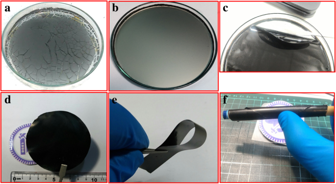
一 破裂的 rGO/MWCNT 薄膜,b 均匀薄膜,c 从培养皿中取出均匀的薄膜,d –f 水洗退火自立膜
结构和形态特征
GO、rGO 薄膜、MWCNT 和 GP10C 的 XRD 图案如图 3a 所示。 XRD 的综合表征代表了所制备薄膜的脱氧。 GO薄膜的XRD图谱表明在2θ处有一个尖锐的衍射峰 =10.4°,对应于GO的特征(001)衍射。这表明更大的层间距 (d =0.8465 nm) GO 比石墨 (~ 0.34 nm) 由于引入了附着在 GO 片表面的含氧官能团(例如,环氧基和羟基)以及单分子厚的存在层之间插入水分子 [32,33,34]。对于 rGO、MWCNTs 和 GP10C 样品,衍射峰出现在 2θ =分别为 26.24°、25.49° 和 25°。由于含氧官能团的破坏,rGO(~ 0.3475 nm)和GP10C(~ 0.36 nm)中层间距的显着收缩表明氧化石墨烯的成功减少。对 rGO/MWCNT 薄膜(图 3b)进行拉曼分析,通过由此产生的分别与缺陷和无序相关的特征 G 和 D 带进一步探索 GO、rGO、MWCNT 和 GP10C 的结构。为了观察石墨烯相关材料中存在的缺陷,强度比(I D/我 G) 对于 D 波段(在 1350 cm −1 ) 和 G 波段(在 1590 cm −1 ) 通常使用 [35]。 ID/IG 比率(插图,图 3b)从 GO 膜的 0.9685 增加到 rGO 纸、MWCNT 和 GP10C 的 1.2123、1.0807 和 1.1649,表明 rGO、MWCNT 和 GP10C 膜中的缺陷比纯去电影。缺陷的增强可能是由于石墨烯片分解成更小的 sp 2 石墨烯域和由含氧基团分解引起的碳原子损失 [36]。 I的价值 D/我 GP10C 薄膜的 G 比(1.1649)小于 rGO 薄膜的 G 比(1.2123),这可以归因于 sp 2 的增量 引入碳纳米管引起的域[37]。在施加 10.0 MPa 的均匀压力 5 min 后,rGO 和 GP10C 薄膜的 N2 吸附-解吸等温线如图 3c 所示。计算出的 GP10C 的 BET 比表面积 (0.9869 m 2 /g) 比 rGO 薄膜 (0.2229 m 2 /G)。更高的比表面积预示着电解离子和电极活性材料之间的界面面积更大,并可能提供更好的电化学性能 [38]。更高的比表面积可归因于 MWCNTs 夹在 rGO 层之间,这防止了 rGO 片在施加外部压力时重新堆叠。为了研究热稳定性,合成薄膜的 TGA 在 N2 环境中以 3 °C min -1 的升温速率完成 从 30 到 900 °C(图 3d)。在 TGA 图中,从 30 到 255 °C,3.2% 的重量损失与表面吸收水的蒸发和层间水分子的去除有关 [39]。在 302 到 810 °C 范围内重量损失约 18.6% 可归因于亲水性官能团的分解,在纯化和合成过程中与 rGO 和 MWCNTs 相连,并与还原的氧化石墨烯和碳的热分解有关纳米管 [40]。我们观察到GP10C薄膜的热稳定性优于纯rGO薄膜,这完全可以归因于独立式GP10C中MWCNT的存在。
<图片>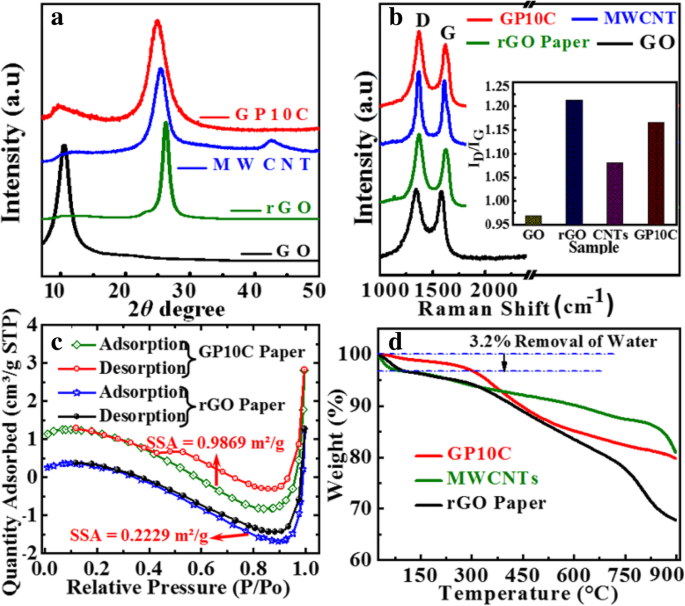
GO、rGO纸、MWCNTs和GP10C薄膜的XRD图谱。 一 , b D和G波段的拉曼光谱演变,c rGO、rGO/CNT 薄膜和 d 的 BET 分析 rGO薄膜、MWCNT和GP10C薄膜的TGA曲线
rGO 和 rGO/MWCNT 薄膜的 FESEM 显微照片如图 4 所示。横截面检查(图 4a)显示 rGO 片在 rGO 薄膜中对齐并重新堆叠在另一个的顶部。我们观察到 rGO 层之间存在一些气穴,这是由于还原和退火过程中氧气和其他气态物质的释放而产生的。这些气穴会降低自支撑膜的导电性,从而降低其电化学性能 [41]。我们观察到,在薄膜中添加 MWCNT 后(图 4b-d),当 MWCNT 作为填料并为气体物质从薄膜中出来提供交替路径时,rGO 层变得更加对齐,并且气穴更少。 <图片>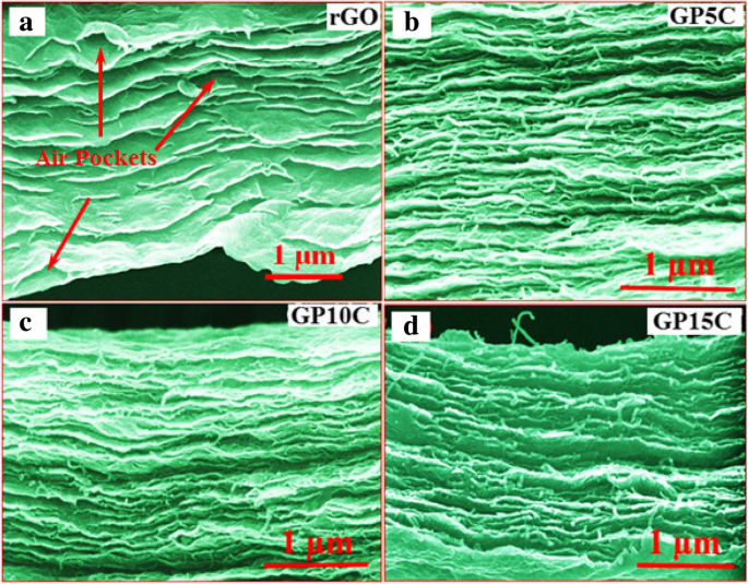
a 的横截面 FE-SEM 图像 rGO 薄膜,加载不同的 MWCNTs b 5 wt.%, c 10 wt.% 和 d 15 wt.%
电导率测量
电导率是研究所制备的 rGO 和 rGO/MWCNT 薄膜的电化学性能的一个非常重要的参数。 GP、GP5C、GP10C和GP15C厚度分别约为0.01、0.015、0.014和0.0165 mm的电气测量是通过四点探针仪器进行的,测得的GP、GP5C、GP10C和GP15C的欧姆电阻为发现分别为 2.94、2.71、1.93 和 2.66 mΩ/sq.(图 5a)。图 5b 描绘了由方程计算的电导率值。 (1) GP、GP5C、GP10C 和 GP15C 为 41.7 × 10 -2 , 51.4 × 10 −2 , 82.9 × 10 −2 , 和 62.9 × 10 −2 S cm −1 , 分别。随着 MWCNT 比率从 0 增加到 10 wt.%,薄膜的电导率增加。这可以归因于薄膜中由 MWCNTs 形成的导电网络的存在。在 rGO 薄膜中添加 MWCNTs 可以形成 3D 网络,作为薄膜内部电荷传输的导电通道,从而提高其导电性。随着 rGO 中 MWCNT 负载的增加,MWCNT 的排列变得不那么明显(图 4b-d)。在较高的 MWCNT 浓度 (15 wt.%) 下,rGO 层之间 MWCNT 的团聚趋势变得有效,从而减少了整个薄膜中 MWCNT 的导电网络形成,因此电导率值降低 [42]。这基本上是由增加接触电阻的影响引起的 [43, 44]。在各种合成薄膜中,GP10C 表现出较低的欧姆电阻值 (1.93 mΩ/sq.) 和较高的电导率 82.9 × 10 -2 S cm −1 . GP10C 电导率的增强是强π -π rGO 和 MWCNTs 之间的耦合促进了两者电子密度之间更多的移动电荷职业离域 [45]。
<图片>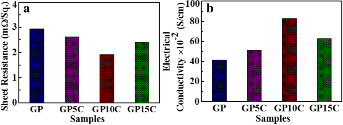
一 具有 5、10 和 15 wt.% MWCNT 含量和 b 的 rGO 和 rGO/MWCNT 纸的欧姆电阻 相同的电导率
GP10C 薄膜在各种碱性电解质中的电化学性能
GP10C 薄膜的电化学性能测量在室温下通过 CV、GCD 和 EIS 在水性电解质中进行。电解质是极大影响超级电容器电化学性能的最重要因素之一。因此,为了找到最适合薄膜电极的碱性电解质,我们研究了 GP10C 电极在三种最常用的碱性电解质中的电化学性能 ,即 KOH、NaOH 和 LiOH,结果如图 6 所示。对于不同的电解质,CV 曲线占据不同的区域(图 6a)。值得注意的是,当扫描速率为50 mVs -1 时,GP10C的CV曲线近似矩形,在KOH中所占的面积比在NaOH和LiOH中更大 .在图6b中,GP10C在电流密度为3 Ag -1 时的GCD曲线 与 NaOH 和 LiOH 电解质相比,KOH 中的放电时间更长。从方程很明显。 (2) 放电时间越长(Δt ),SC 就越高。因此,与 2 M LiOH 和 NaOH 电解质相比,我们在 2 M KOH 中获得了更高的 SC(图 6c)。观察到的 GCD 曲线不对称(图 6b)是由于复合膜表面发生了一些法拉第反应。这种现象可以归因于与 rGO 片和功能化 MWCNT 相连的含氧官能团。 EIS 基本上用于在离子转移和电导率方面执行薄膜的电化学性能。 GP10C 在不同电解质中的奈奎斯特图在 0.1 Hz 到 100 KHz 的频率范围内进行检查,交流幅度为 5 mV(图 6d)。 GP10C 的奈奎斯特图基本上包含两个主要分量(实部 Z′ 和虚部 Z″ ) 表示一个复平面,其中 Z' 表现出欧姆行为;另一方面,Z″显示薄膜电极的电容行为。理论上可以通过三个频率相关区域来解释,即高频区(阻抗弧)、低频区和中频区(Warburg阻抗)。
<图片>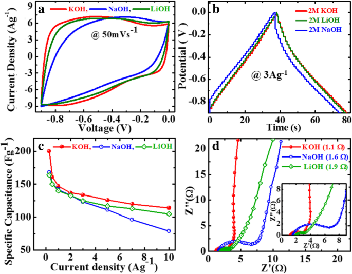
GP10C薄膜在2 M电解质中不同KOH、LiOH和NaOH水溶液中的电化学性能,a 50 mVs −1 时的CV曲线 , b GCD曲线在3 Ag -1 , c 根据 GCD 曲线计算的 SC,以及 d 各种电解质中的奈奎斯特图,插图显示放大区域
超级电容器在较高频率范围内的工作方式类似于纯电阻器,而在较低频率下,虚部和几乎垂直的直线急剧增加,表现出纯电容行为。中频区代表电解离子与薄膜电极多孔活性位点之间的相互作用。此外,在 EIS 中,电解质的离子电阻、集电器和活性材料的内阻以及电极-集电器界面接触电阻对于找出有效串联电阻 (ESR) 或溶液电阻 (Rs) 起着关键作用。在奈奎斯特曲线的高频区域,可以通过曲线与实轴相交的点值来观察ESR。发现 KOH 的 Rs 值(~ 1.1 Ω)小于 NaOH(~ 1.6 Ω)和 LiOH(~ 1.9 Ω)的值。还值得注意的是,高频区半圆弧的直径和中频区45°角的斜线长度分别是扩散阻力和Warburg阻力的代表。在这方面,与 LiOH 和 NaOH 相比,GP10C 在 KOH 中表现出较小的扩散阻力和 Warburg 阻力 [46, 47]。 GP10C电极在KOH中的优异性能可能与较小的水合离子半径和较高的K
+
离子电导率有关 离子 (64.3 Ohm
−1
厘米
2
mol
−1
) 与 Na
+
相比 (43.5 欧姆
−1
厘米
2
mol
−1
) 和 Li
+
(33.5 欧姆
−1
厘米
2
mol
−1
) 离子。另一方面,较低的水合离子半径 K
+
增强了离子迁移率 离子进入电极表面,从而提高了 GP10C 电极的电化学性能 [48, 49]。 K
+
的简单解释 , Na
+
, 和 Li
+
水合离子半径分别为 232、276 和 340 pm 的离子如图 7 所示。根据公式 F =KQ 1问 2/r
2
,其中 F 是库仑力,r 是两个电荷之间的距离 (Q 1 和 Q 2 ) 和 K 是库仑常数。离子半径遵循rK+ (=138 pm)> rNa
+
的顺序 (=102 pm)> r Li
+
(=76 pm),所以库仑力遵循K
+
的顺序

Schematic diagram of hydrated ionic radii of the ions associated with different electrolytes used for GP10C electrode measurement
Electrochemical Performance of rGO/MWCNT Films
We also investigated the effect of MWCNT addition on the electrochemical performance of rGO/MWCNT films in a three-electrode setup with 2 M KOH electrolyte. Figure 8a depicts the CV curves of as-synthesized rGO, GP5C, GP10C, and GP15C film electrodes recorded at a scan rate of 50 mVs −1 in the potential range − 0.9 to 0.0 V. Evidentially, in comparison to GP, GP5C, and GP15C, the CV curve of GP10C occupies the larger area, and it belongs to nearly rectangular shape, implying the electrical double-layer (EDL) capacitive behavior of this electrode with higher SC value [52]. Figure 8b represents the GCD curves of all the films recorded at 1 Ag −1 in the potential range − 0.9 to 0.0 V. Furthermore, similar to CV results, the charge/discharge curves being nearly triangular in shape also verify the electrical double-layer capacitor (EDLC) behavior of the film electrodes. Here, it is clear that the GP10C has significantly longer discharge time (∆t ), and hence higher SC among the synthesized films. The values of CVs calculated from the GCD curves using Eq. (2) as function of discharge current densities are shown in Fig. 8c. The GP10C exhibits specific capacitances of 200, 161, 147, 137, 134, 123, 120, and 114 Fg −1 at 0.25, 0.5, 1, 2, 3, 5, 7, and 10 Ag −1 , respectively, and it is able to maintain ~ 57% of its initial capacitance value (200 Fg −1 ) from 0.25 to 10 Ag −1 . The specific capacitance of rGO increases significantly after the addition of MWCNTs, which is obvious from the electrochemical performances of GP5C and GP10C samples. The improved electrochemical performances of the composite can be ascribed to the fact that CNTs prevent the restacking of rGO sheets and hence facilitate the electrolytic ions to move deeper into the film samples. As the amount of CNTs is increased beyond the optimum value, specific capacitance decreases, which can be ascribed to the limited dispersibility and poor specific capacitance (~ 20 F/g) of MWCNTs [53, 54].

Electrochemical performance of rGO, GP5C, GP10C, and GP15C electrodes in 2 M KOH electrolyte, a CV curves at the scan rate of 50 mVs −1 , b GCD curves at the current density 1 Ag −1 , c CV as determined from GCD curves, and d Nyquist plots comparison of all the papers
Moreover, the specific capacitance of all the synthesized films decreases with an increase in the current density because the diffusion of electrolytic ions into the film electrodes becomes slower at higher current density values. Figure 8d shows the Nyquist plots of all the electrodes, indicating that with an increase of MWCNT content, internal resistance starts to decrease. The internal resistance is the Ohmic resistance, which consists of ionic resistance of electrolyte, inherent resistance of substrate and active electrode material, and contact resistance at the active electrode material and substrate interface. GP10C film electrode demonstrates the smallest internal resistance (1.14 Ω), while the internal resistances for rGO, GP5C, and GP15C are found to be about 2.2, 1.41, and 1.19 Ω, respectively. The smaller value of internal resistance for GP10C film can be ascribed to the better contact and its higher electrical conductivity. The “knee” frequency is defined as the highest frequency value at which impedance of the system is dominated by the capacitive nature [55]. It is related to the diffusion coefficient and effective diffusion length of the active electrode material. Further, at the frequencies higher than knee frequency, the electrolytic ions come across semi-infinite diffusion and finite diffusion at the frequencies lower than this [56, 57]. The knee frequency values for GP5C, GP10C, and GP15C are 1.37, 1.49, and 1.10 Hz, respectively. The higher knee frequency value for GP10C implies that lesser time is required by the charge species to accumulation at the interface for this sample. Further, it is well documented that larger semicircle at higher-to-medium frequency region corresponds to the larger charge-transfer resistance (Rct) [31, 58]. The Rct for GP15C film seems to be quite higher than that of GP10C, that may be due to its lower electrical conductivity and higher contact resistance with aqueous electrolyte [59].
Further, EIS data can be used to find out the relaxation time constant (τ 0) of the devices like supercapacitors in terms of complex power with the help of Eqs. (8) and (9). Relaxation time constant (τ 0) is an important parameter and considered as a factor of merit for a supercapacitor. To determine the relaxation time constant, normalized imaginary factor (|Q |/|S |) and real factor (|P |/|S |) of power are plotted vs. frequency (in logarithmic scale) (Fig. 9). Both these two curves cross each other at a point called resonance frequency (f °), which is utilized to calculate the relaxation time of a supercapacitor using the following formula:τ 0 = 1/2πf 0 [49]. From the graphs, we observe that at a higher frequency, |P |/|S | attains maximum value, which implies maximum power dissipates in the system, i.e., supercapacitor behaves similar to pure resistor. As the frequency decreases, |P |/|S | decreases up to a point at which |Q |/|S | attains the highest value. At this point, supercapacitor works similar to a pure capacitor. Evidently, for all the tested films GP(rGO), GP5C, GP10C, and GP15C, both the |P|/|S| and |Q|/|S| curves act contrarily with frequency variation and cross each other at resonance frequency (f °). The relaxation time constant values for GP, GP5C, GP10C, and GP15C as calculated using resonance frequencies are 1.3 s, 196 ms, 194 ms, and 378 ms, respectively. After adding MWCNTs in the rGO film, relaxation time decreases remarkably. This may be due to the fact that CNTs prevent the restacking of rGO sheets and hence allow the electrolytic ions to move faster into the film. As the amount of MWCNTs increases further (15 wt%) in the rGO film, increment in the relaxation time constant is observed. This can be ascribed to the smaller diameter of MWCNTs (10–20 nm) that offers higher ionic diffusion resistance, which become significant as the amount of MWCNTs is increased beyond optimum value [60, 61]. EIS results can also be used to determine the diffusion coefficients of the synthesized films for electrolytic ions (Fig. 9d). The calculated diffusion coefficients (D a) of electrolytic ions at the interfacial region using Eq. (7) come out to be 1.0112 × 10 −13 , 8.0286 × 10 −9 , 7.8457 × 10 −9 , and 2.1919 × 10 −9 for GP, GP5C, GP10C, and GP15C, respectively, in 2 M KOH. It can be seen that the relaxation time constant and diffusion coefficient of GP5C and GP10C are almost the same, but the Cs and rate capability of GP10C is much better than those of GP5C. The small relaxation time constant and high diffusion coefficient of GP10C film electrode, allow it to deliver stored energy quickly, and high specific capacitance make it desirable for engineering high-power capacitors.

一 –c are the normalized real part |P|/|S| and imaginary part |Q|/|S| of the complex power as a function of frequency for GP, GP5C, and GP10C, respectively, and d Randles plots of all the synthesized electrodes
From the above results, GP10C film-based supercapacitor electrode exhibits the best electrochemical properties among the synthesized films. Therefore, we investigate its electrochemical performance in detail. Figure 10a indicates the CV curves of GP10C at 5, 10, 25, 50, and 100 mVs −1 in the potential range − 0.9 V to 0.0 V vs Ag/AgCl reference electrode. It is shown that all the CV curves possess almost rectangular and symmetric shape, indicating the perfect EDL capacitive behavior and fast charging/discharging characteristics. The inset in Fig. 10a shows nearly a linear relationship between average peak current and the square root of the scanning rate with correlation coefficient R 2 = 0.98878. This phenomenon indicates that the electrochemical process in the film is a diffusion-controlled process [62]. Figure 10b represents the GCD curves of GP10C evaluated at 0.25 to 10 Ag −1 in − 0.9 to 0.0 V. During the charge/discharge process, the corresponding curves also verify that the charging curve of GP10C is almost symmetric to its corresponding discharging curve. To evaluate the durability of the GP10C, the long cycle test was carried out in 2 M KOH electrolyte at 2 Ag −1 . Figure 10c depicts the long cycle stability, which is another important parameter to examine the electrochemical performance of an electrode material. After 15,000 cycles, GP10C electrode exhibits excellent retention of 92.5%. The inset in Fig. 10c shows first and last 5 successive cycles. It demonstrates that even after 15,000 cycles, the electrode maintains good symmetric charge/discharge characteristic features, which verify its excellent electrochemical durability. Figure 10d represents the Nyquist plots of the GP10C electrode recorded during long cycle test. It can be observed that the value of internal resistance goes higher during cycling process from the first cycle to 15,000 cycles. GP10C electrode shows lowest internal resistance (1.12 Ω) during the first cycle and after 10,000 and 15,000 cycles, as the electrochemical active sites in the electrode are slowly consumed, the values of internal resistance increases from 2.64 to 3.04 Ω, respectively. As a consequence of it, CV value decreases slowly and repeatedly during electrochemical cycling (Fig. 10c). Furthermore, to find out any morphological changes in the GP10C film electrode after long cycle test, we performed ex situ studies (FESEM and TEM), and the results are shown in Fig. 11. Figure 11a shows the TEM images of GP10C electrode before the long cycle test, while Figs. 11b and c represent the FESEM and TEM images of the GP10C after 15,000 cycles. We can see that the morphology of the GP10C electrode does not change even after 15,000 cycles, which reveals the sustained chemical stability of the film. The observed capacitance of GP10C film electrode is higher than those of several recently reported free-standing graphene-based supercapacitor electrodes as shown in Table 1.

Electrochemical performance of GP10C in 2 M KOH electrolyte a CV curves at the scan rate of 5, 10, 25, 50, and 100 mVs −1 ; b GCD curves at the current densities of 0.25, 0.5, 1.0, 2.0, 3.0, 5.0, 7.0, and 10 Ag −1 ; c cyclic stability performance for GP10C electrode at 2 Ag −1 and inset shows the GCD curves of first and last 5 cycles;和 d Nyquist plot for the GP10C and inset shows the EIS performance during 1st, 10,000 and 15,000 cycles

一 TEM images of the CP10C electrode before long cycle test and b FESEM and c TEM images of the CP10C after 15,000 cycles
Electrochemical Performance of Symmetrical Supercapacitor
Further, to investigate the practical application of the GP10C film, we made a symmetric coin cell supercapacitor using two GP10C electrodes of identical weight separated by a separator in 2 M KOH aqueous electrolyte. Figures 12a and b show the CV profiles of the device at the scan rates of 2, 5, 10, 15, 25, 50, 75, and 100 mVs −1 . We can observe nearly identical rectangular shape, which implies the perfect EDLC behavior of the supercapacitor. Figure 12c represents the linear GCD curves at all current densities demonstrating the high rate response of the device. Moreover, the smaller internal resistance (0.4 Ω) of the coin cell indicates better charge transportation in the supercapacitor (Fig. 12d). The calculated specific capacitances from CVs of the device (Fig. 12e) are 53, 51, 49.8, 48, 46.7, and 45 Fg −1 at 0.1, 0.2, 0.3, 0.5, 0.7, and 1.0 Ag −1 , 分别。 From the capacitance profile (Fig. 12e), it is clearly shown that the device retains 85% of its initial capacitance value at current density 0.1 Ag −1 up to 1 Ag −1 , i.e., good rate capability. Additionally, we calculate the energy density (Whkg −1 ) and power density (Wkg −1 ) of the device using equations given below [8, 9]:
$$ E=\frac{\mathrm{Cs}}{2\times 3.6}{\left(\Delta V\right)}^2 $$ (8) $$ P=\frac{E}{\Delta t}\times 3600 $$ (9)
Electrochemical performance of GP10C/KOH/GP10C symmetrical coin supercapacitor cell a , b CV curves of GP10C/KOH/GP10C coin cell at 2, 5, 10, 15, 25, 50, 75, and 100 mVs −1 , c Nyquist plot, d GCD curves of the device at different current densities, e SC at different current densities, f Ragone plot
where Cs is the SC calculated from the GDC curves, ∆V is the potential window, t is the discharge time (s).
The device exhibits maximum and minimum energy densities of 29.4 and 25.0 Whkg −1 at power densities of 439 and 4500 Wkg −1 , respectively (Fig. 12f).
This symmetric device shows excellent retention of ~ 85% and columbic efficiency of 92% after 10,000 successive cycles at 0.3 Ag −1 (Fig. 13a). The excellent cyclability of the device can be ascribed to the electrochemical stability of the active electrode material. In the GP10C nanocomposite film, the optimum amount of MWCNTs mainly prevents the restacking of rGO sheets and thus offers a more exposed area to the electrolytic ions for surface adsorption. This also strengthens the material structure to resist the structural deformation upon cycling. The ex situ TEM and FESEM micrographs of the tested electrode after 15,000 cycles (Fig. 11a–c) verify the behavior that the morphology of GP10C electrode remains the same even after 15,000 cycles, which reveals the sustained chemical stability of the synthesized composite film. The inset in Fig. 13a shows the GCD profiles of 1st, 5000th, and 10,000th charge-discharge cycles, indicating the symmetric charge/discharge characteristic features of the device. The high retention at even after 10,000 continuous long cycles verifies its outstanding electrochemical durability. Figure 13b depicts the Nyquist plots of the device during long cycle test, implies that with repeated cycles, the Warburg region in the middle frequency region is increasing. It can be attributed to the consumption of active sites presented in the active material of the supercapacitor electrodes during a long cyclic test, which results in an increase of the internal resistance of the device. The inset (Fig. 13b) shows that our symmetric coin cell can light up a red LED. Further, our designed FSSSD using GP10C flexible film electrodes and gel electrolyte depicts no significant changes in the shape of CV curves when bending the device at angles from 0 to 180° at a scan rate of 20 mVs −1 (Fig. 13c). Digital photographs of the device under the bending angles 0°, 60°, 90°, and 180° are shown in Fig. 13d–g, respectively.

The long cycle performance of GP10C/KOH/GP10C symmetrical coin cell. 一 Cyclic stability and columbic efficiency recorded at 0.3 Ag −1 for 10,000 successive cycles, and inset shows the GCD profiles of 1st, 5000th and 10,000th GCD cycles. b Nyquist plots recorded just after 1st, 5000th and 10,000th cycles, and inset shows a red LED light up by single coin cell. c The CV curves at a scan rate of 20 mVs −1 of symmetrical solid state flexible device using gel polymer electrolyte under different bending angles. Digital photographs of the device under different bending angles, d 0°, e 60°, f 90°,and g 180°, respectively
The above results prove the potential applications of our synthesized GP10C film for the supercapacitors. Moreover, this facile approach may open future prospects for energy storage devices application.
结论
In summary, simple and cost-effective rGO/MWCNT flexible film electrodes were synthesized via simplest chemical route. The effects of MWCNT addition on the electrochemical performance of rGO/MWCNT nanocomposite films were investigated in different alkaline electrolytes, KOH, LiOH, and NaOH. Based on experimental findings, GP10C exhibits the best electrochemical performance in 2 M KOH with SC of 200 Fg −1 . This synthesized film electrode demonstrates excellent durability with 92% retention after 15,000 long cycle test, small relaxation time constant (~ 194 ms), and high diffusion coefficient (7.8457 × 10 −9 厘米 2 s −1 ) in 2 M KOH aqueous electrolyte. The superior electrochemical performance of GP10C can be attributed to the smaller hydration sphere radius and higher ionic conductivity of K + 阳离子。 The symmetric coin supercapacitor cell using GP10C as both anode and cathode and 2 M KOH as electrolyte exhibits perfect EDLC behavior with maximum energy and power densities of 29.4 Whkg −1 and 4500 Wkg −1 , 分别。 Our symmetric cell demonstrates excellent retention of 85.3%, and columbic efficiency of 92% after 10,000 successive cycles at 0.3 Ag −1 . Further, the designed FSSSD using GP10C flexible film electrodes and gel electrolyte depicts no significant changes in the shape of CV curves when bending the device at angles from 0 to 180° at 20 mVs −1 . We believe that our rGO/MWCNT nanocomposite film is suitable for practical applications and appropriate for designing high capacitive energy storage (supercapacitors or Li-batteries), conversion, and wearable devices.
数据和材料的可用性
All data and materials are fully available without resection.
缩写
- 赌注:
-
布鲁诺-埃米特-特勒
- 简历:
-
循环伏安法
- EDLC:
-
Electrical double-layer capacitor
- EIS:
-
电化学阻抗谱
- FESEM:
-
Field-emission electron microscope
- GCD:
-
Galvanostatic charge/discharge
- 开始:
-
氧化石墨烯
- GP:
-
rGO/MWCNT film with 0% CNT ratio
- GP10C:
-
rGO/MWCNT film with 10% CNT ratio
- GP15C:
-
rGO/MWCNT film with 15% CNT ratio
- GP5C:
-
rGO/MWCNT film with 5% CNT ratio
- HI:
-
Hydriodic acid solution
- MWCNTs:
-
Multiwall carbon nanotubes
- PVA:
-
Polyvinyl alcohol
- rGO:
-
还原氧化石墨烯
- SC:
-
Specific capacitance
- TEM:
-
透射电子显微镜
- TGA:
-
热重分析仪
- XRD:
-
X射线衍射
纳米材料
- 应用聚焦:轴承 3D 打印
- 应用聚焦:鞋类 3D 打印
- 用于合成和生物医学应用的荧光纳米材料的进展和挑战
- 用于超级电容器应用的石墨烯和聚合物复合材料:综述
- 重吸收抑制的 II 型/I 型 ZnSe/CdS/ZnS 核/壳量子点的合成及其在免疫吸附测定中的应用
- 合成单分散二元 FePt-Fe3O4 纳米粒子的后处理方法
- InP/ZnS 核/壳量子点的绿色合成在无重金属发光二极管中的应用
- ZnO 纳米晶体的合成及其在倒置聚合物太阳能电池中的应用
- 用于透明导体应用的柔性铜纳米线网状薄膜的紫外线处理
- 聚(3,4-亚乙基二氧噻吩)/金/石墨烯复合材料的固态加热合成及其在安培法测定亚硝酸盐和碘酸盐中的应用
- 碳纳米纤维和活性炭作为水性电解质中对称超级电容器的研究:一项比较研究
- 水热合成 CoMoO4 微球作为超级电容器的优良电极材料