

钢连铸自动化、仪器仪表和建模
钢连铸的自动化、仪表和建模
钢水连铸工艺是将钢水凝固成半成品钢产品(钢坯、大方坯、梁坯、圆钢或板坯)以供随后在轧机中轧制的工艺。连铸机的基本操作是通过初冷区、喷冷区、矫直机等一组操作,将给定成分的钢水转化成所需形状和尺寸的铸坯。
连铸过程主要包括 (i) 一个位于结晶器上方的中间包,它接收来自钢包的钢水并以规定的速率将其送入结晶器,(ii) 一个由水冷组成的主冷却区钢水从中间包送入铜模具,以产生足够坚固的凝固钢外壳,以在钢坯进入二级冷却区时保持钢坯的形状,(iii) 二级冷却区与定位的安全壳部分相关联在模具下方,钢绞线(仍然主要是液体)通过模具并被喷洒水或水和空气的混合物(气雾)以进一步固化钢绞线,(iv)用于伸直和矫直钢绞线的部分钢绞线,(v) 由割炬或机械剪组成的切割部分,用于将凝固的钢绞线切割成所需的长度以便移除,以及 (vi) 用于冷却的输出辊道林床或直接到产品转运区。
钢的连铸过程是一个复杂的工艺过程,包括传热、钢液的凝固过程、钢液的流动以及从液态到固态的相变等问题。这涉及到创建最佳过程控制系统的相当大的困难,该系统将包括钢水连铸过程中可能发生的所有物理化学现象的影响。正因为如此,连铸过程的控制是炼钢过程中最困难的任务之一。
连铸过程由于其复杂性而伴随着几种物理现象。钢液在结晶器内和离开结晶器后进入二冷区的凝固过程中,这些重要现象最多。在主冷却区,发生的部分过程是 (i) 钢水湍流通过复杂几何区域和由对流引起的浸入式入口喷嘴或护罩,(ii) 钢水内的热传递区域,(iii) 成型壳和模具壁之间的模具内热传递,(iv) 热流通过固态和液态熔渣层,(v) 热应力的形成,(vi) 与凝固壳相关的收缩到钢凝固过程中发生的转变,(vii)伴随凝固现象的热效应,(viii)模具壁对凝固铸坯的机械冲击,(ix)模具壁和凝固之间形成气隙的过程(x) 在凝固区内形成晶体并伴有元素偏析。
表面缺陷的形成发生在二冷区。在该区域发生的过程是(i)液芯区域内的热传递(传导和对流),(ii)凝固壳层中的热传导,(iii)伴随凝固现象的热效应,(iv)由喷嘴系统对铸坯冷却产生的多级传热,与喷涂区的数量和所应用的冷却类型有关,(v) 凝固铸坯的收缩,与钢凝固过程中发生的转变有关,(vi)单个凝固区(枝晶区和等轴晶区)的形成,以及 (vii) 与轧辊与铸坯接触相关的应力的形成,以及连铸机轧辊之间鼓胀的可能性。
钢连铸的自动化、仪器仪表和建模有几个驱动因素。这些驱动因素包括客户对质量的更高要求、竞争加剧、更严格的环境法规以及更高的安全要求。此外,连铸机的整体生产系统要确保与前后单元的工艺一致性。此外,连铸过程自动化系统还需要执行基本任务,包括生产计划和调度、质量保证以及更常规的监督控制功能。
连铸过程的过程控制需要精密的仪器来完全控制铸坯凝固过程。连铸机的测量系统提供了大量的工艺信息。但是,缺少关键信息,例如机器各个点的壳厚度变化和冶金长度(液芯的长度)。因此,数学模型对于连铸过程的控制系统极为重要。这些数学模型的准确性使其可用于在过程中做出技术决策。
自动化和仪表系统以及数学模型提高并保证了连铸产品的质量,并以各种方式减少机器停机时间。已经开发了包含数学模型的专家系统。不断提高的质量要求带来的新挑战以及解决连铸过程中各种众所周知的问题的新思路,导致了过程自动化和控制方面的一些进步。
用于连铸过程的现代自动化系统使用多个数学模型来模拟铸造过程的不同阶段。这些计算的输入数据由一级自动化的特定传输适配器实时获取。铸造工艺的目标参数由给定的生产程序或操作者指定。专家系统用于计算工艺参数的最佳值,控制生产质量,对工艺过程的不同状态进行即时建模,并检查轧辊和段的设置。专家系统是二级自动化的一部分。清晰的软件架构和稳定的数据传输中间件平台对于不同自动化系统、专家系统和操作人员之间的成功交互具有重要作用。
HMI(人机界面)指导操作员完成生产过程。操作人员的互动仅限于与质量和安全相关的活动。重要信息的概览显示在主显示屏上,并且可以通过大量专用屏幕轻松访问详细信息。操作员屏幕以操作人员理解的语言和单位显示。整个系统包括一组可配置的应用程序,用户可以选择预定义的文本而不是输入它们。图为典型的连铸自动化系统。
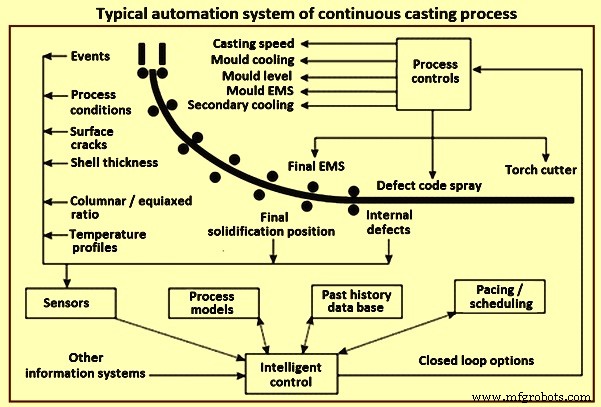
图1典型的连铸自动化系统
自动化系统的层次结构
在设计和开发连铸机工艺过程的自动化和控制系统时,定义了自动化系统的责任级别、要求和响应的以下分类。
0 级自动化 – 它包括对单个单元的控制。自动化区域内的各个单元使用连接的传感器、传感器、旋转传感器、驱动器、控制和控制电路进行控制。直接手动控制通过单元、驱动器和联锁装置执行,这些联锁装置依次由 0 级自动化系统处理。大多数安全机制也存储在此级别。
1 级自动化 – 它通过PLC(可编程逻辑控制器)控制控制成组的单元。 一级自动化系统处理的任务包括一个自动化区域内多个设备的控制系统。控制任务通常由 PLC 模块和微控制器实时执行,PLC 控制的保证系统响应时间间隔为 20 毫秒 (ms) 到 150 毫秒,微控制器在 10 毫秒到 20 毫秒之间(对于例如,运动控制器)。由于这些系统响应时间的严格限制,复杂的生产过程模型无法实现,例如,与使用移动单元的物料跟踪和覆盖计划相关的任务被委托给其他自动化级别。
连铸机的 1 级自动化功能通常包括 (i) 转塔、引锭车和中间包的控制,(ii) 引锭杆位置的确定,(iii) 驱动辊的调整,( iv) 宽度调节、模具锥度和模具液位控制,以及 (iv) 根据初级和次级冷却系统中选定的设定点调节空气和水
2 级自动化 – 2 级自动化用于过程控制。 2 级自动化系统在确定生产过程的效率和质量保证方面发挥着至关重要的作用。 2 级自动化系统使用操作工程师或相关标准预先定义的指令和设置来管理和监控铸造过程。此外,每个铸造指令都包含一组质量评估参数,这些参数表明生产目标产品质量的最佳条件。使用一组冶金模型意味着铸造过程可以完全自动化,从而最大限度地减少操作员输入或干预的需要。流程模型连接所有院系以实现优化的整体绩效。
2 级自动化系统负责以下领域:(i) 生产质量保证,(ii) 过程控制以及向 1 级自动化系统传输命令和参数,(iii) 自动化生产数据采集,(iv) 模拟和使用工艺流程的综合数学模型预测系统状况,(v) 材料跟踪,(vi) 使用移动设备优化材料处理和覆盖规划系统,以及 (vii) 警告和故障指示系统,包括生产评估故障和整定次数。
连铸工艺的 2 级自动化系统要求包括 (i) 在铸造过程中收集和显示工艺参数,(ii) 计算铸坯、铸坯表面和边缘的 3D 温度分布,(iii)计算铸坯壳的生长、凝固长度、边缘收缩、氧化皮和其他铸造特性,(iv) 铸坯二次冷却系统的动态定位,(v) 执行节段的动态调整(软压下),(vi ) 跟踪材料变化和凝固位置,以及 (vii) 接受和转发操作员干预。
二级自动化中通常包含的程序和模型包括 (i) 带止动机构的钢水流量控制,(ii) 结晶器液位控制,(iii) 结晶器粉末液位控制,(iv) 自动启动铸造,( v) 防脱模系统,(vi) 模具、拉条和最终搅拌,(vii) 液压模具振荡,(viii) 热跟踪模型,(ix) 实时质量评估,(x) 切割优化模型,( xi) 实时铸坯凝固模型,(xii) 在线/离线凝固曲线计算器,(xiii) 动态机械软压下,(xiv) 动态二次冷却控制,(xv) 铸件打标机,(xvi)光学产品识别系统,(xvii) 过程分析和模拟,(xviii) 冶金数据管理,(xix) 生产延迟检测,(xx) 设备寿命跟踪,以及 (xxi) 铸造产品处理物流,包括三次冷却。
在为连铸过程实施 2 级自动化控制功能时,复杂的数据结构用于对领域的各种技术术语进行建模。除其他外,使用喷涂计划、空气计划、参考温度曲线、铸造粉末、铸造参数数据集、钢种、化学参考分析、钢种组、裂纹和样品切割从不同角度检查问题域的映射关于典型的冶金问题。此外,数学模型、控制机制和用户界面需要对连铸过程进行简化、标准化的描述,其中明确定义了与计算相关的真实对象的属性,例如铸流引导、结晶器、节段、轧辊、喷嘴、二次冷却控制回路和冷却段。通过引入简洁的、特定领域的语言可以很容易地描述所提到的术语。
在连铸的情况下,1 级或 2 级自动化系统的任务不能总是被清楚地分类。关于每个单独自动化任务的放置和分配的结论取决于输入参数和过程数据的本地化、嵌入式模型的可能响应时间、所需的存储空间以及自主程度。要求经常分布在两个系统之间,例如材料跟踪,有些甚至是重复的,例如安全联锁。两个系统都有自己的用户界面,通常是为各自的自动化级别任务而设计的。
3 级 – 3 级自动化用于生产计划。它处理生产计划的生成,例如铸造程序、工作调度和准备,或商店管理,以及维护计划、停机时间和维护任务。
分布式二级自动化系统的软件架构 – 2 级自动化系统需要满足的重要要求是集成数学模型与 1 级控制系统、3 级规划系统、连接的数据库以及与连铸机操作人员的稳定和安全的通信.在 Level 2 自动化的设计和配置过程中,不同组件的种类、接口和连接的数据源很重要,每个组件的行为逻辑都不容小觑。
集成在二级自动化系统中的数学生产过程模型构成了过程控制系统的核心。通过监控过程的实际状态,可以为模型持续提供来自 1 级自动化系统的实际值。另一方面,数据还补充了短期计划结果,以及来自 3 级自动化系统的物料和订单数据。计算结果和生产过程的整体视图显示在连铸机的用户界面上,供操作人员使用。操作人员的任何必要的过程控制干预都可以通过使用 1 级自动化系统输入掩码(例如速度设置)和 2 级自动化系统用户界面(例如更改控制方案(参考温度和喷涂计划控制))来执行.
多种软件架构模式用于实现此类系统,其中通常包括模型(多代理架构)、事件和消息调度器(事件驱动架构)和分布式服务(面向服务架构)。
仪器
自连铸早期以来,仪器一直在连铸机上使用。在连铸机的每个主要部件上都使用了仪器,这些部件位于转塔或钢包车以及用于铸造产品的跳动辊道之间。仪器广泛用于连铸机,用于监测钢包、中间包、结晶器、二冷区、辐射区和跳动辊道的变量,如图 2 所示。控制铸造参数被认为是连铸机生产率和质量取得巨大进步的主要因素之一。
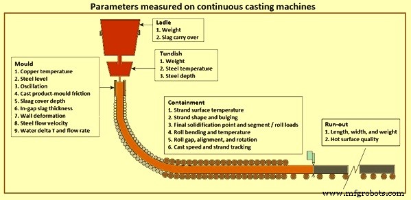
图 2 在连铸机上测量的参数
仪器对于任何控制和自动化系统都至关重要,它们对实现现代生产力和质量标准的贡献不容小觑。仪器是控制和自动化系统的“眼睛”,在现有技术下,工艺和质量控制系统可以使用永久性仪器来“看到”最重要的钢包、中间包和模具变量。
连铸过程中仪器的主要功能是(i)测量用于控制连铸机械和冶金功能性能的参数,(ii)为每个铸件分配质量等级,(iii ) 诊断操作和机器问题,(iv) 开发将产品质量和生产率与铸机设计和操作相关联的知识。
连铸机上使用的仪器的数量和精密度一直在迅速增长。快速增长的主要原因是对更高生产率和铸件质量的不断增长的需求,以及现代在线数字计算机的可用性。对于质量和生产率要求最严格的板坯连铸机来说尤其如此。早些时候,重点放在模具仪器上,因为模具实践和参数对产品质量和生产率的影响最大。但近年来,在钢包、中间包、安全壳、连铸机出料辊道等方面的仪器开发和应用取得了重大进展。
鉴于在连铸机二冷区喷淋室内发现的危险环境,连铸机控制系统经常对关键工艺变量(例如铸坯表面温度)的变化“视而不见”也就不足为奇了。区。这里使用的仪器通常是临时性质的,因此是在实验基础上使用的。其他重要的仪器包括用于测量辊间鼓胀、凝固壳厚度和模具/铸坯摩擦的仪器。
连铸过程建模
对钢连铸过程进行建模是一项非常复杂的任务,可以使用各种类型的数学模型来完成。目前,不可能同时捕捉到连铸整个过程中发生的所有影响,并以单一综合数值模型的形式呈现。连铸过程建模中应用的自然划分与试图识别钢水实际铸造过程中随之而来的问题,或关注过程的选定部分以改进现有技术有关。
在问题解决的早期阶段,正确选择模型类型及其适应所解决问题类别的相关可能性一直是一项艰巨的挑战。从理论上讲,更复杂的模型(即更“智能”)可以轻松回答有关铸造过程主要技术参数的问题。然而在实践中遇到了许多限制。假设复杂模型已被验证为正确,在最好的情况下,需要不必要地延长计算时间。这是因为模型计算的参数比解决定义问题所需的参数多得多。设置问题的复杂性与所用工具的“智能”不同步导致的第二个危险是模型参数的验证问题及其与过程数据的相关性。模型的理论化程度越高,参数越多,出现不可测参数的风险就越高。最后一条评论涉及获取所需模型参数值的知识的策略问题。多年的连铸过程建模经验表明,最好的选择是对所有可测量的模型参数进行实验测量。可以通过铸钢的比热随温度、钢的热导率、粘度等参数的形式来说明。
物理建模 – 连铸过程的物理建模,例如使用水模拟钢水,可以深入了解连铸过程中钢水的流动行为。以前对连铸过程中流体流动的理解主要是通过使用物理水模型的实验来实现的。这种技术是在流程中实施新配置之前测试和了解新配置效果的有用方法。全尺寸模型具有提供操作员培训和理解的重要额外好处。
物理模型的构建是基于满足模型和实际过程之间的某些相似性标准,即通过匹配支配重要感兴趣现象的几何形状和力平衡。为了用水模型重现钢水流动模式,两个系统中所有主导力之间的比率都应相同。这确保了模型和钢铁工艺之间的速度比在每个位置都是相同的。无量纲组的大小表示两种力的相对重要性。非常小或非常大的组可以忽略不计,但铸造过程中所有中间尺寸的无量纲组都需要在物理模型中进行匹配。要选择合适的几何比例和流体来实现这些匹配。
幸运的是,水和钢具有非常相似的运动粘度。因此,雷诺数和弗劳德数可以通过构建全尺寸水模型同时匹配。满足这两个标准就足以在等温单相流系统(例如连铸水口和结晶器)建模中达到合理的精度,并且已经取得了巨大的成功。
全尺寸模型具有易于测试机器组件和操作员培训的额外好处。实际上,任何几何尺度的水模型对大多数流动系统都能产生合理的结果,只要两个系统中的速度都足够高以产生完全湍流和非常高的雷诺数。由于流经中间包和模具喷嘴的流量是重力驱动的,因此在这些系统的任何水模型中,只要水头和几何形状都按相同的比例缩放,弗劳德数通常都能满足。
物理模型有时要满足热相似性标准。例如,在钢包和中间包中稳定流动的物理流动模型中,热浮力相对于主要的惯性驱动流动较大,如修正的弗劳德数的大小所示,因此在模型中应保持相同就像在液态钢系统中一样。在难以估计速度的钢包中,检查雷诺数的平方除以修正的弗劳德数(称为格拉肖夫数)是很方便的。惯性在模具中占主导地位,因此在那里可以忽略热浮力。热浮力的相对大小可以在全尺寸热水模型中匹配。然而,这并不容易,因为控制热损失的现象取决于流体传导率和比热以及容器壁传导率等特性,这些特性在模型和钢容器中是不同的。在其他系统中,例如那些涉及低速、瞬态或凝固的系统,同时满足其他几个对传热很重要的相似标准几乎是不可能的。
连铸过程的复杂性和支配它的现象如图 3 所示,使得很难有物理模型。然而,随着计算机硬件和软件的日益强大,数学建模已经成为控制连铸过程各个方面的重要工具。
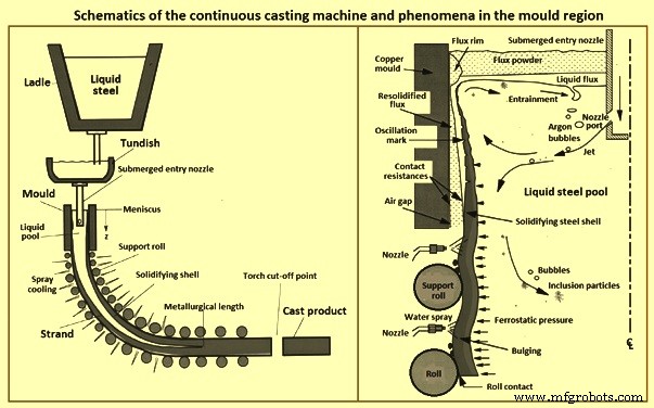
图3连铸示意图及结晶器区现象
计算或数学建模 – 目前,计算成本的降低和商业建模包的强大功能使得应用数学模型作为理解钢水连铸过程中复杂材料工艺步骤的附加工具变得更加容易。计算模型的优点是易于扩展到其他现象,例如传热、粒子运动和两相流,而这是等温水模型难以做到的。计算模型还能够更忠实地表示钢水所经历的流动条件。例如,不需要物理底部来干扰离开流水模型的流动,并且可以考虑移动凝固壳的存在。
数学模型现在可以模拟大多数对连铸过程很重要的现象。这些包括 (i) 受氩气气泡、热和溶质浮力影响的复杂几何形状(入口喷嘴和线状液池)中的完全湍流、瞬态流体运动,(ii) 粉末和钢相内部和之间的热力学反应, (iii) 漂浮在钢顶表面的液体和固体通量层内的流动和热传输, (iv) 自由液体表面和界面的动态运动,包括表面张力、振荡和重力引起的影响(v) 过热通过湍流钢水的传输,(vi) 溶质的传输(包括等级变化期间的混合),(vii) 复杂几何夹杂物在液体中的传输,包括浮力、湍流相互作用和夹杂物在喷嘴壁、气泡、凝固钢壁和顶表面上的可能截留的影响,(viii) 弯月面区域中的热、流体和机械相互作用在凝固弯月面、固体渣缘、渗透的液态熔剂、钢水、粉末层和夹杂物颗粒之间,(ix) 通过凝固钢壳、壳和模具之间的界面(包含粉末层和不断扩大的气隙)的热传递, 和铜模具,(x) 粉末沿着外壳和模具之间的间隙的质量传输,(xi) 模具壁和支撑辊的变形和磨损,(xii) 固体晶体的成核,无论是在熔体中还是在模具中(xiii) 钢壳的凝固,包括枝晶、晶粒和微观结构的生长、相变、沉淀物的形成和微偏析, (xiv) 凝固钢壳由于热收缩、相变和内部应力,(xv) 由于外力(模具摩擦、支撑辊之间的鼓胀、退缩和重力)而在凝固钢壳内产生的应力,(xvi) 热应变、蠕变和塑性在微观和宏观尺度上(随温度、等级和冷却速度而变化)、(xvii) 裂纹形成和 (xviii) 耦合偏析。
连铸过程的惊人复杂性使得不可能同时对所有这些现象进行建模。因此,有必要做出合理的假设,并解耦或忽略不太重要的现象。定量建模需要结合所有影响特定问题的现象。因此,每个模型都需要一个特定的目的。一旦选择了控制方程,它们通常会被离散化并使用有限差分或有限元方法求解。进行充分的数值验证很重要。
在求解非线性方程时,数值误差通常源于计算域太粗或收敛不完全。解决已知的测试问题并进行网格细化研究以实现与网格无关的解决方案是帮助验证模型的重要方法。最后,模型需要在实验室和工厂规模的实验测量中进行检查,然后才能可信地对参数研究的真实过程进行定量预测。
模型的最终测试是结果是否可以实施并可以实现改进,例如避免钢铁产品中的缺陷。这种实施最终需要进行工厂试验。试验将根据所有可用来源提供的见解进行,包括物理模型、数学模型、文献和以前的经验。随着计算能力不断提高,数值模拟工具的能力不断提高,建模在未来向高科技连铸工艺的发展中发挥着越来越重要的作用。建模可以增强传统研究方法,以生成和量化改进过程任何方面所需的理解。 Areas where advanced computational modelling plays a crucial role in future improvements include (i) transient flow simulation, (ii) mould flux behaviour, (iii) taper design, (iv) on-line quality prediction and control, especially for new problems and processes such as high-speed billet casting, thin slab casting, and strip casting.
Future advances in the continuous casting process are not going to come from models, experiments, or plant trials. They are going to come from ideas generated by people who understand the process and the problems. This understanding is rooted in knowledge, which can be confirmed, deepened, and quantified by tools which include computational models. As the computational tools continue to improve, their importance is increasing in fulfilling this important role, leading to future process advances.
The assumed computing objective and the required accuracy are to be the key in selecting the model. In several cases, the desired information is knowledge of the metallurgical length of the strand and the dynamics of changes in the shell thickness. This is the case when determining a place for carrying out the so‐called soft reduction operation. As can happen when the strand casting speed needs to be changed, a procedure allowing a new cooling intensity to be determined is needed. A problem like this does not need answering a series of questions related to stress occurring in the strand, the structure formed, or potential cast strand defects. Thus, it is understandable that the model is naturally simplified to a form, which still provides a credible answer to the questions which needs solution.
Some of the important models used in the automation and control of the continuous casting process are given below. The models are normally incorporated at the Level 2 automation level.
Dynamic secondary cooling control – There is a third dimension in the dynamic secondary cooling control. The model set up takes the precision and control possibilities to the next dimension allowing completely new philosophies for secondary cooling and soft reduction. When setting up the secondary cooling system, it is prerequisite to consider all known parameters which have a known influence to the calculation of 3-dimensional temperature profile of the strand. All different nozzle types are measured at the nozzle test stand to evaluate the spray water distribution. This derived information is input to the maintenance and setup system (MSS) of the 3D model. The visualized spray distribution can be seen in the maintenance system.
The exact positions of the nozzles in the cooling zones are entered and the spray distribution of one zone can be seen in the MSS. The heat removal of a cooling zone is calculated considering the heat removal of the spray water, rolls, and heat radiation. The MSS allows all cooling-relevant settings to be configured in such a way that the spray-water distribution in the cooling zones and the application of cooling practices are optimized for continuous casting machines. Metallurgical know-how can be easily incorporated into the automation setup. A built-in off-line simulation system enables comprehensive testing of new parameter settings prior to application in the production process.
The Level 2 automation system for secondary cooling provides a mathematical model for calculating the temperatures on the strand surface and inside the strand as a function of the spray plan to be used, the interpolation points in the reference temperature curve, or in relation to time changes for the spray water quantities across the complete machine. The dynamic secondary cooling control system can handle three control regimes namely (i) temperature control, (ii) strand age, and (iii) spray plan control.
In the temperature control regime the dynamic secondary cooling control system calculates the volumes of water for strand secondary cooling which are needed to maintain the specified reference temperature on the strand surface. The strand age regime is one way of controlling the secondary cooling process, taking into account the change in parameters over a given period of time. With the spray plan control regime a spray plan is produced for secondary cooling whereby preset spray water volumes correspond to a specific casting speed. As the change in casting speed takes effect, the spray water volumes are also immediately modified, and the resulting temperatures on the strand surface are displayed to the continuous casting machine operator. If temperature scanners are used in the plant, the dynamic secondary cooling control system is able to adapt to the values delivered by the scanners, so that the coefficients of the strand temperature field calculation can be adapted to the values measured.
Dynamic 3D secondary cooling system – The first-generation dynamic solution was characterized by a two-dimensional temperature calculation of the strand centre. The strand corners were largely neglected by the process model. Continuous improvements in computer performance have now made it possible to calculate the temperature at any point within the entire strand in real time, in a full three-dimensional mode and in a sufficiently fine discretization yielding very detailed temperature profiles as can be seen for strand surface and strand centre.
The model is based on an explicit finite-volume approximation which solves the heat transfer equation and takes into consideration temperature-dependent material properties such as density as well as the position-specific cast product thickness and width. Dynamic 3D secondary cooling system accurately assesses the heat transfer from the cast product surface resulting from radiation, heat transfer to the rolls, natural convection and spray water. Further, the dynamic 3D secondary cooling system can be applied for both spray cooling and air-mist cooling and takes into account the spray distribution pattern of the nozzles and the actual spray water temperature. This ensures an accurate spray-cooling heat transfer prediction to temperatures below 700 deg C when the Leidenfrost phenomenon disappears. The result is an even more precise determination of the strand surface-temperature profile and the final point of strand solidification.
Based on the precise temperature calculations the dynamic 3D secondary cooling system allows specifying the desired surface temperature not only along the strand length, but also across the strand width. Even individual control of the water flow and positioning of each cooling nozzle is possible. The control algorithms of the dynamic 3D secondary cooling system calculate the water flow set-points to achieve the target strand surface temperature values. Pyrometer measurement results show an excellent fit in between calculated and measured lateral strand temperature profile.
Application of the dynamic 3D secondary cooling system allows introducing completely new philosophies to set up cooling practices for upcoming challenges in continuous casting. The combination with moveable spray nozzles (3D sprays) yields unprecedented quality results.
The advanced secondary cooling dynamic 3D model derives correct water flow rates even in transient casting situations such as steel grade changes, casting speed variations, different tundish temperatures, tundish exchanges, and at the beginning and end of a casting sequence. The water flow rate for each cooling zone is calculated to maintain a defined surface temperature profile throughout the entire casting sequence. The maintenance system allows the process engineer to change cooling practices easily and introduce continuous casting shop specific cooling expertise. The off-line simulation system is used to test the effect of the new settings in various casting situations before utilization in the production process.
Dynamic phase calculation of material properties – In order to calculate a 3-dimensional temperature profile of the strand, material properties like enthalpy, solid fraction, density, and conductivity as a function of the temperature are to be known. In case, these properties are experimentally known for a given steel grade composition, these functions can be entered by the process engineers in the MSS, which is very time-consuming. Normally the process engineer does not know these thermo-physical properties. The software model calculates all the thermo-physical data used by 3D model. Dynamic phase calculation of material properties is available as an on-line tool to determine the material properties for the current steel grade analysis.
The traditional approach is to define the thermo-physical properties for grade groups with a pre-defined concentration range of the chemical analysis. Using the dynamic phase calculation, these data can be calculated for each individual steel grade. This makes the prediction of quantities such as the point of complete solidification on the strand and the temperature distribution of the strand during casting more accurate and hence allows for precise metallurgical treatments which can lead to an improved quality of the products. Further, the model indicates whether the current analysis of the steel is peritectic or not and alerts the operator in the event of an unexpected peritectic grade. This can reduce the risk of breakouts and improves quality.
The dynamic phase calculation is based on thermodynamical models. The liquid-solid phase transformation in the high temperature range is described by a Gibbs free energy model in combination with a micro-segregation model. For solid-solid phase transformations in the low temperature range an Avrami type model is employed. The free parameters of the models are determined with the help of experimentally measured quantities. Using off-line simulations of dynamic phase calculation together with the 3D model allows metallurgical development of new steel grades.
Traditionally the steel grades are grouped and a typical chemical analysis for the group is used to determine the material properties. With dynamic phase calculation, the material properties are derived from the actual steel analysis. Calculations can show that there can be a difference in the point of final solidification of half a meter or even more by comparing the results of the actual steel analysis versus the grade group analysis. This fact shows the importance of having an on-line calculation of the actual steel grade in order to improve the quality of the cast products.
Dynamic gap soft reduction – Dynamic gap soft reduction stands for dynamic roll-gap adjustment in the continuous casting process. This is made possible by specially designed strand-guide segments – known as ‘smart segments’ in which the roller gaps can be remotely adjusted for strand thickness changes and for improved internal strand quality. On the basis of the on-line information provided by the dynamic 3D thermal-tracking model, the dynamic gap soft reduction dynamically calculates the set points of the adjustable roll gap.
Supervision of the roll engagement, depending on the state of solidification (liquid, mushy, or solid) and the calculated strand-thickness profile, is a decisive factor for precise roll adjustments and thus improved product quality. An optimized roll engagement also reduces excessive forces on the strand and decreases roller wear. The more accurate control of the roller gaps allows additional casting strategies to be implemented such as liquid-core reduction and intentional bulging soft reduction. IE。 intentional dynamic gap increase before the soft reduction area allows for higher thickness reduction in this area. This further improves the casting flexibility and the product quality.
Dynamic gap soft reduction makes it possible to freely define scenarios for start-up, tundish change, and tail out strategies based on the strand thickness, steel grade, and casting status. In this way roll damage and production interruptions, which can arise from the different casting behaviour of the cold strand head or end, can be avoided.
Nozzle expert for early clogged nozzle detection – Cooling water is sprayed through nozzles onto the strand with the objective of achieving uniform cooling of the steel. However, if one or more of these nozzles are clogged, then a section of the strand cannot be uniformly cooled to the required temperature. This can lead to surface defects, and the cast product possibly has to be down-graded. The issue of changing segments in the continuous casting machine is also a source of difficulty. Hoses can easily be ruptured or jammed. Aware of the consequences of leakages or clogged nozzles, maintenance personnel spend a large number of working hours checking whether nozzles are operating properly.
The nozzle expert helps to detect clogged nozzles and broken hoses in the continuous casting machines and thus ensures that the strand is evenly cooled for high quality steel production. It automatically monitors the condition of the nozzles during the casting process. The model can also be manually activated during casting breaks. The advantage is that nozzle status can be checked following maintenance work or segment changes and immediately repaired before the casting process is restarted.
The model calculation considers parameters like nozzle type (measuring results from the nozzle test stand), height between pressure measuring device, water pressure, pipe lengths, pipe diameters, and nozzle positions. Any modifications to the secondary cooling system e.g. use of different nozzle types needs a change in the set-up of the nozzle expert in order to get correct computational results.
The nozzle expert is based on statistical models and indicates the clogging ratio in each zone (e.g., zone 2 nozzles clogged 10 % with a probability of 96 %). Operators need only to inspect zones for which an alarm is generated. Calculations begin automatically with the start cast signal, and the condition of the nozzles is monitored throughout the casting process. Several alarms help to detect leakages, clogged nozzles, and even falsely installed nozzles on a segment.
Inter-mix expert – It improves yield by prior simulations. During sequence casting, a mixing of steel grades takes place in the tundish and therefore in the strand with each ladle change. On the basis of the chemical composition of the steel, the inter-mix expert calculates whether the mixed steel zones can be used for the foreseen product application or if the steel has to be downgraded or even scrapped. Information acquired from tundish flow experiments combined with analysis results of steel samples taken from solidified products ensures a high degree of accuracy of Inter-mix predictions with respect to the actual composition of the mixed steel zones.
The inter-mix expert determines traces of the previously cast heat present in the current heat. Steel mixing takes place not only in the tundish but also in the mould and upper parts of the strand. Mixing in these areas is evaluated by a mix-box-type sub-model of inter-mix which makes it possible to calculate the chemical composition of the steel at any position along the cast strand.
Tundish changes or the use of separator plates are treated individually. Inter-mix calculations are cyclically performed for selected chemical elements starting with the ‘ladle open event’ of a new heat. The final decision about the compatibility of heats cast in sequence is performed by the heat-assignment function of inter-mix. The concentration profiles of certain critical elements which have an impact on the final product disposition (prime, downgraded, or outright rejection) are determined. A deviation is detected if one of the critical elements does not match the steel-grade specification.
The full benefit from the inter-mix model is achieved by combining the model output with the yield expert model which assures maximum prime quality yield by applying cut-length optimization to incompatible steel areas along the strand which are designated as scrap.
Process engineers work with the powerful simulation environment, which makes it possible to simulate any combinations of different steel grades. Input parameters like analysis, tundish weight, and dimensions of the strand can be easily entered and modified and the computed results are made visible in the HMI. Graphs are displayed for single analysis elements or combinations of more elements. Valuable information like volume concentration, mixed steel length, scrap length, and heat ranges on the strand are shown on the bottom of the graphs.
Configuration of the model can be easily done in the MSS. The process engineer can choose which chemical elements are to be used to determine the inter-mix for any grade link. A powerful simulation environment allows simulating the mixing behaviour of two different grades and the computed volume concentration, calculated analysis along the strand, and heat ranges including possible scrap sections are displayed.
Speed expert – The speed expert model is for the optimum casting speed in any casting situation. Selection of a proper casting speed on the continuous casting machine is of high importance. Several aspects (e.g. quality, safety, machine limits, and production requirements) influence the choice of the casting speed. These different aspects are frequently contradictory such as increase in production calls for a high casting speed whereas the safety requirements limit the casting speed. Normally, several continuous casting shops have self-made software solutions to calculate the casting speed considering different aspects. The aim of the speed expert is to cover most aspects and to provide an easy maintenance tool which enables the process engineer to adjust the behaviour of the speed expert to the special needs.
The speed expert calculates cyclically the optimum casting speed. The calculation of the casting speed is based on various rules, which consider the different aspects and are specified in the speed expert practice. Each rule determines a speed range which satisfies its requirements. The speed expert first determines the inter-section of all these speed ranges. If the inter-section is not empty, then it selects a casting speed depending on the predefined strategy, which can be maximum speed, aim speed, or avoid speed changes as long as actual casting speed is in the valid range. If there is a conflict between the different rules, then the inter-section is empty. In this case the pre-selected conflict resolve strategy is applied which can be (i) priority (lower priority rules are to be neglected till a solution can be found), or (ii) minimum of maximum speed (the smallest of all maximum speeds is to be selected).
On the on-line HMI the casting machine operator can view the speed ranges of all rules and the derived optimum casting speed. The casting operator can change the priorities of the different rules, the strategy, and the conflict resolve strategy to fine adjust the calculation if necessary. Speed set-points are sent to Level 1 and can be executed automatically.
MSS is used to define the speed expert practice considering (i) quality related rules consisting of quality expert rule, minimum / aim / maximum speed for the steel grade, superheat, Mn/S ratio, low tundish weight, and optimum soft reduction, (ii) production related rules consisting of heat pacing, start cast, and clearing, and (iii) safety related rules consisting of machine protection, and forecast calculation for minimum and maximum speed.
Optimum soft reduction can be achieved if the final point of solidification is at the end of a strand segment. A pre-calculation assuming steady state conditions determines the required casting speeds for each strand segment.
Yield expert – The aim of the yield expert is to minimize scrap and to optimize the yield. It considers scrap portions, quality defects, weight restrictions, sample cuts, and width changes while producing the maximum number of scheduled products. The important features of the yield expert are (i) optimization of product length or product weight in the case of scrap sections or quality-related defects, (ii) scheduling of mould width adjustments, (iii) scrap section allocation algorithms, (iv) optimization steps can be switched on-line and off-line, and (v) replay of cut-to-length optimization steps, even in actual production situations
Quality expert – Quality expert determines the definitions necessary for the quality-related process parameters, tracks the actual data during production, predicts the quality of the cast products, and automatically determines the subsequent product disposition. It supports the continuous casting machine operators by on-line quality alerts and a preview of the quality of the cast strands in the casting machine. Quality expert is of two distinct types distinguished by basic or comprehensive product quality rating capability.
All the tracked information and calculation results can be transferred from the production module of the quality expert to the so-called discovery system. This system is dedicated to the long-term archiving and evaluation of the huge amount of information tracked.
制造工艺