氧化石墨烯对无源碱性直接乙醇燃料电池中 QPVA 基膜的乙醇渗透性和离子电导率的影响
摘要
被动碱性-直接乙醇燃料电池(碱性-DEFC)似乎适合为便携式设备生产可持续能源。然而,乙醇交叉是被动碱性-DEFC 系统的主要挑战。本研究调查了交联季铵化聚(乙烯醇)/氧化石墨烯(QPVA/GO)复合膜在降低乙醇渗透性方面的性能,从而提高了被动碱性-DEFC 的性能。对复合膜的化学和物理结构、形态、乙醇吸收和渗透性、离子交换容量、吸水率和离子电导率进行了表征和测量,以评估它们在燃料电池中的适用性。膜的传输性能受 GO 负载量的影响,最佳负载量为 15 wt.%,掺杂 1 M KOH 的乙醇渗透率最低(1.49 × 10 -7 厘米 2 s −1 和 3.65 × 10 −7 厘米 2 s −1 分别在 30°C 和 60°C)和最高的离子电导率(1.74 × 10 -2 S cm −1 和 6.24 × 10 −2 S cm −1 分别在 30°C 和 60°C)。在被动碱性 DEFC 中,最大功率密度为 9.1 mW cm −2 ,高于商用 Nafion 117/KOH (7.68 mW cm −2 ) 在 30°C 下使用 2 M 乙醇 + 2 M KOH 溶液。对于 60 °C,复合膜的最大功率密度为 11.4 mW cm −2 .
介绍
燃料电池是一种将燃料的化学能直接转化为电能而无需任何燃烧的电化学装置。与传统方法相比,该技术提供电能的效率更高; 60%的燃料转化能够实现,而传统方法需要几个转化步骤来产生电能[1]。在各种类型的燃料电池中,直接乙醇燃料电池 (DEFC) 是一种很有前途的便携式电源,因为与其他类型的燃料电池相比,它易于储存燃料、设计简单且使用的燃料毒性更低 [2,3, 4].
对于便携式电源设备应用,由于燃料输送概念和易于操作,与有源 DEFC 相比,无源 DEFC 似乎更合适和可靠。被动供料系统采用天然毛细管力,不涉及任何用于燃料和空气呼吸的泵,为氧化还原反应提供氧气。因此,不需要额外的功耗。单个电池的紧凑轻巧的结构可以开发为紧凑的设备,这与需要外部泵和鼓风机的有源电池不同,从而扩大了电池[5,6,7]。不幸的是,被动 DEFC 的两个缺点阻碍了它们的商业应用:阳极的电动反应缓慢和从阳极到阴极的高乙醇渗透率 [8]。目前,由于其高质子传导性和高机械稳定性,Nafion® 用于 DEFC,也用于酸性和碱性介质中的其他类型的燃料电池。然而,Nafion® 膜有几个阻碍 DEFC 商业化的缺点,包括乙醇屏障差、生产成本高(高于美国能源部 ~ 40 美元/m 2 ),以及在其生产中使用有害材料。 DEFCs 的高乙醇渗透率导致功率损失和阴极催化剂污染 [8,9,10]。
为了解决上述被动 DEFC 问题,研究人员探索了被动碱性直接乙醇燃料电池(碱性-DEFC)作为替代系统。被动碱性-DEFCs 在碱性条件下工作,与酸性条件系统相比具有以下优势:(1) 阳极催化剂中乙醇氧化的速率更高,(2) 使用非铂催化剂的成本,例如 Ag或 Ni,较低,并且 (3) OH − 流动方向与膜中的乙醇扩散流相反,因此由于离子运动的影响减少,因此可以显着减少乙醇在膜中的交叉[11,12,13]。作为“DEFC 的心脏”,阴离子交换膜的使用近年来得到了广泛的研究[8]。商业季铵 AEM 可以传导氢氧根阴离子;不幸的是,AEM 的导电性仍然很差。此外,传统 AEM 中的官能团在较高浓度的碱性燃料消耗中是必需的,并且在操作温度超过 60°C 时会降解 [14,15,16,17]。因此,被动碱性DEFC应用迫切需要一种替代AEMs的膜。
聚乙烯醇 (PVA) 是一种有吸引力的聚合物,由于其优异的耐化学性、机械稳定性和作为燃料屏障的能力,它有可能取代商业 AEM。此外,PVA 膜的制备很简单,因为成膜过程非常容易,并且其羟基的亲水性有利于交联反应的反应位点的高密度,从而提高了膜的机械性能和热稳定性 [18, 19,20,21]。 PVA 基膜的最大功率密度可达 8.0 mW cm −2 在碱性-DEFC 被动模式和 82 mW cm −2 的环境条件下 如先前研究 [4, 13] 中报道的,在 80 °C 下,碱性-DEFC 的活性模式。
在碱性介质中,PVA 掺杂的氢氧化钾 (KOH) 使 PVA 成为一种有效的稳定电解质,形成氢键和偶极-偶极相互作用,从而在 AEM 的稳定结构中产生良好的离子导电性 [22,23,24,25 ]。根据之前的研究,基于 KOH 掺杂的 PVA 膜可以耐受芬顿溶液(例如氧化还原环境)并表现出显着的耐化学性 [23, 26]。因此,与其他阴离子交换膜相比,这种组合对碱处理具有更高的化学稳定性。当纳米填料被整合到 PVA 基体中时,物理交联机制可以进一步提高尺寸稳定性并抵抗在水中的溶解和乙醇的交叉。此外,PVA 是一种廉价的材料,可降低 DEFCs 的制造成本,并且无毒且可生物降解,使其成为一种绿色材料 [11, 23, 27, 28]。
不幸的是,如果用作 AEM,PVA 有两个主要缺点,包括离子电导率差和由于高吸水率导致的高溶胀率 [29, 30]。将季铵官能团引入到 PVA 基质中对提高离子电导率起着重要作用。季铵化聚乙烯醇 (QPVA) 源自用缩水甘油三甲基氯化铵 (GTMAC) 对 PVA 进行改性。 QPVA 解决了离子电导率低的问题,同时提高了亲水性和水的选择性[31,32,33,34]。熊等人。 [31]报道QPVA膜的离子电导率为7.34 × 10 -3 S cm −1 作为 AEM,而 Yang 等人。 [34] 已经成功地将基于 QPVA 的膜的离子电导率提高到 2.11 × 10 -2 S cm −1 在 60°C。然而,根据我们的知识,尚未开展任何工作来发现基于 QPVA 的膜在被动碱性-DEFC 系统上的潜力。
正如之前的工作所报道的,基于 QPVA 的膜具有高吸水率,这导致高燃料渗透性并降低机械强度。这种情况可以通过与无机填料或其他聚合物混合形成 QPVA 复合膜 [35, 36] 来改善。拉杰什·库马尔等人。 [37] 报道了基于 QPVA 的膜的乙醇渗透率很高,范围在 (0.95–2.08) × 10 -6 厘米 2 s −1 .在这项研究中,QPVA 与氧化石墨烯 (GO) 结合作为 AEM,以提高具有低乙醇渗透性和高离子电导率的被动碱性 DEFC 的性能。目前,GO 是应用最广泛的无机材料,因为它具有特殊的特性,包括提高聚合物的热和机械强度的潜力,由于存在丰富的功能而具有良好的网络能力。由于 GO 边缘存在含氧官能团,包括羟基、羧基和环氧基团,因此 GO 作为聚合物电解质中的填料是一个很好的候选者。该亲水区域有助于将阴离子转移到聚合物电解质中 [38,39,40,41]。卡里姆等人。 [42]报道GO的离子电导率接近10 -2 S cm −1 高于块状氧化石墨 (10 −4 S cm −1 )。此外,芳环中的疏水区(sp 2 由于强共价键合,GO纳米片结构的碳层有助于减少燃料交叉问题并提高机械强度[40,41,42,43,44]。林等人。 [44] 报道称,GO 片材能够降低 Nafion®115 膜的燃料渗透性,直至 10 -7 厘米 2 s −1 .叶等人。 [45]将PVA/GO电解质膜应用于碱性直接甲醇燃料电池以提高电池性能,使离子电导率增加约126%,燃料渗透率降低55%。
显然,之前没有研究过研究交联 QPVA/GO 复合膜在被动碱性-DEFC 系统中的性能。本研究的目的是制备一种具有合适纳米填料负载量的自合成 QPVA 基膜,可有效降低乙醇交叉,从而提高被动碱性 DEFC 的性能。在溶液浇铸方法中,自制的 GO 分散在 QPVA 聚合物基质中,以提高膜性能。通过液体吸收、离子交换容量、离子电导率和乙醇渗透性等多项测试评估了制备的具有不同 GO 负载量和掺杂 1 M KOH 的交联 QPVA/GO 复合膜的性能。 GO 的最佳组成是根据膜选择性测量的最佳性能确定的。交联 QPVA/GO 复合膜与氢氧化钾 (KOH) 掺杂的商用 Nafion 117 膜(设计为 Nafion 117/KOH)之间的性能比较已被检验,以在被动碱性-DEFC 中提供碱性电解质膜,并且它可用作替代AEMs在被动碱性DEFCs中的应用指南。
方法论
材料
聚(乙烯醇)(PVA)(Mw 85,000–124,000,99 + % 水解)、石墨粉、硝酸钠 (NaNO3)、高锰酸钾 (KMnO4) 和缩水甘油三甲基氯化铵 (GTMAC) 由 Sigma Aldrich 提供。戊二醛(GA,25% 的蒸馏水)由日本 Nacalai Tesque 提供。磷酸 (H3PO4)、硫酸 (H2SO4)、盐酸 (HCl)、氢氧化钠 (NaOH) 和氢氧化钾 (KOH) 购自 J.T. Baker 和过氧化氢 (H2O2) 购自 HmbG Chemical。所有这些商业材料均未经任何纯化使用。
季铵化PVA的合成
将适量的 PVA 溶解在去离子水中,同时用磁力搅拌器在 90°C 下搅拌 2 小时。当所得 PVA 溶液变得均匀、透明和粘稠时,将溶液的温度降至 65°C。接着,加入适量的 GTMAC 和 KOH(GTMAC:KOH =1:1 摩尔比),并将所得均匀无色溶液连续搅拌 4 小时。向溶液中加入无水乙醇,得到季铵化聚乙烯醇(QPVA)黄色沉淀,然后在真空烘箱中干燥。
氧化石墨烯的合成
Hummer 的方法用于合成氧化石墨烯 (GO) [46]。在容量瓶 (500 mL) 中将 2 克石墨与 2 克 NaNO 3 混合。然后,将 150 mL 的 H2SO4 添加到混合物中,并将混合物在冰浴(0-5°C)中连续搅拌 30 分钟。接下来,将 12 g KMnO4 添加到混合物中,并将反应温度保持在 20°C 以下 4 小时。移除冰浴,并将反应在 35°C 下搅拌 1 天,直到溶液呈糊状和棕色。接下来,将溶液用 100 mL 去离子 (DI) 水稀释以形成棕色溶液。然后,添加 200 mL 水以降低温度。最后,倒入 10 mL H2O2 处理溶液,观察到黄色。离心机用10% HCl纯化溶液,纯化步骤用去离子水冲洗数次。
交联 QPVA/GO 复合膜的制备
交联 QPVA/GO 复合聚合物膜的制备步骤示意图如图 1 所示。QPVA(8 wt.%)通过磁力搅拌在 75°C 下完全溶解在去离子水中 1 小时,形成均匀的和透明的溶液。通过稀释 GO 溶液 (1 g/L) 提供具有不同 GO 含量 (5 wt.% 至 20 wt.%) 的溶液。 QPVA 溶液在加入 GO 溶液(2:1 体积比)的同时连续搅拌 1 小时,以产生黄褐色 QPVA/GO 溶液。将黄褐色溶液与 10 重量%的 GA 连续搅拌 30 分钟。将溶液浇铸到塑料板上并控制溶液体积以固定膜的厚度 (0.015 mm)。然后,在环境条件下干燥 24 小时,然后在 60°C 的真空烘箱中干燥 12 小时。将膜从塑料板上剥离并放置在玻璃板上,用于在 100°C 下退火 1 小时。然后,将膜浸入 80°C 的 1 M KOH 溶液中 24 小时。用去离子水反复冲洗去除膜表面多余的KOH,使用前将膜置于去离子水中室温保存。
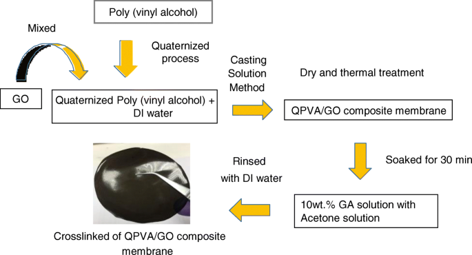
QPVA/GO复合膜制备示意图
复合膜的结构和形态特征
傅立叶变换红外光谱分析
原始 PVA 膜、原始 QPVA 膜和交联 QPVA/GO 15 wt.% 复合膜的红外吸收光谱在具有 ATR(衰减全反射)模块的 Perkin Elmer 傅里叶变换红外光谱 (FTIR) 上记录。将样品固定在样品架中并置于 ATR-FTIR 系统中。 FTIR 研究在环境温度下进行,光谱范围为 400–4000 cm -1 .
X 射线衍射
从交联的 QPVA/GO 复合膜获得 X 射线衍射(XRD,D8 Advance 型,Bruker AXS Germany)测量值以检查它们的结晶度。 X 射线辐射是使用来自阳极的 Cu Kα 辐射(波长为 0.15406 nm)产生的,操作功率为 40 kV 和 40 mA。扫描速率为0.5°s -1 , 分辨率为 0.02°。从10°到50°的角度记录XRD光谱。
场发射扫描电子显微镜 - 能量色散 X 射线光谱、透射电子显微镜和原子力显微镜
使用蔡司 SUPRA 55 VP 场发射扫描电子显微镜 (FESEM) 在 10 kV 下观察交联 QPVA/GO 复合聚合物膜的表面和横截面形态。能量色散 X 射线光谱 (EDX) 用于元素映射。干膜在液氮中冷却后人工破碎。透射电子显微镜(TEM-Hitachi HT 7700,日本)和原子力显微镜(AFM)显示剥落的GO的存在和大小。
热重分析
通过热重分析(TGA)测定复合膜的热性能。 PVA 膜、QPVA 膜和 QPVA/GO 复合膜样品在氮气气氛下以 10°C min -1 的增量从环境温度加热到 600°C 使用热重分析仪(TGA Q500 V20.13 Build 39)。
膜吸收、溶胀比、离子交换能力和氧化稳定性
膜的碱、水和乙醇吸收量由交联 QPVA/GO 复合膜在水合前后的损失重量确定。通过将膜样品在 30°C 下浸入 2 M KOH 24 小时来进行碱吸收程序。然后,将样品从 KOH 中除去,用薄纸除去样品的表面湿气,并立即将样品在微量天平上称重以获得湿膜重量(W 湿)。然后,将样品在 100°C 的炉中干燥 2 小时以确定干燥的膜重量 (W 干燥)。碱吸收(W ) 使用以下公式计算。 (1):
$$ W=\frac{W\ \mathrm{wet}-W\ \mathrm{dry}}{W\ \mathrm{dry}}\times 100 $$ (1)对于水和乙醇的吸收,通过用水和2M乙醇代替溶液处理来修改程序。
通过浸入 100 mm 2 检测交联 QPVA/GO 复合聚合物膜的溶胀率 样品在 25°C 的去离子水中放置 24 小时。然后,将样品从去离子水中取出,用纸巾除去表面湿气,测量膜的厚度,得到湿膜厚度(t 湿)使用千分尺(Mitutoyo,± 1 μm)。然后,将样品在 100°C 的炉中干燥 2 小时以确定干燥厚度 (t 干燥)。溶胀比(Sr DI 水)使用以下公式计算。 (2):
$$ Sr=\frac{t\ \mathrm{wet}-t\ \mathrm{dry}}{t\ \mathrm{dry}}\times 100 $$ (2)经典滴定法用于测量复合膜的离子交换容量(IEC)。将复合膜浸泡在 0.1 M NaOH 溶液中,将其转化为 OH - .然后,用去离子水洗涤复合膜以去除过量的 NaOH,并用 100 mL 的 0.1 M HCl 溶液平衡 48 小时。接下来,IEC 值由使用反滴定测量的酸减少量确定。用于计算 IEC 值的公式 (meq g −1 ) 如下:
$$ \mathrm{IEC}\kern0.37em \left(\mathrm{meq}.{\mathrm{g}}^{\hbox{-} 1}\right)\kern0.5em =\kern0.75em \frac {M_{\mathrm{b}}-{M}_{\mathrm{a}}}{m\} $$ (3)其中 M b 表示平衡前所需的 HCl 毫当量 (meq),M a代表平衡后所需的HCl,m 为干燥后的复合膜的质量(g)。
氧化稳定性测试通过 Fenton 试剂(含 2 ppm FeSO4 的 3% H2O2 水溶液)测量。将样品(40 毫米 × 40 毫米)浸入 25°C 的芬顿试剂中。 24 小时后记录浸泡前后的膜重量。样品在溶液中开始破裂或熔化时膜的任何变化都是其最长测试时间的通知。
离子电导率、乙醇渗透率和选择性因子
使用连接到阻抗分析仪恒电位仪/恒电流仪 (WonATech-WMPG1000) 的四电极电导率电池测定离子电导率,用于从 E-I 曲线的斜率获得膜复合材料的电阻 [47]。所有测量均使用等式进行。 (4):
$$ \sigma =\frac{L}{RS} $$ (4)其中 σ, L , R , 和 S 代表质子电导率 (σ, S cm −1 ), 反电极之间的距离 (L, cm), 膜的电阻 (R, S −1 ), 以及膜样品的截面积 (S, cm 2 ), 分别。交联的 PVA/GO 复合膜在去离子水中在不同温度(30-60°C)中平衡。膜横向放置并夹在电极之间。
构建包含两个玻璃隔室的扩散池以确定膜乙醇渗透性。两个隔间玻璃被分成进料隔间,其中填充有 2 M、4 M、6 M 或 8 M 乙醇,以及第二个隔间,其中填充有去离子水。每个隔室包含用于溶液搅拌的磁力搅拌棒。膜被垂直夹在两个玻璃隔室之间 [47]。在实验过程中,测量了穿过膜的乙醇浓度。使用以下公式计算膜渗透率。 (5):
$$ P=\frac{1}{Ca}\left(\frac{\Delta Cb(t)}{\Delta t}\right)\left(\frac{LVb}{A}\right) $$ ( 5)其中 P 代表膜的乙醇扩散渗透率(cm 2 s −1 ), Ca 代表细胞 A 中饲养室的浓度 (mol L -1 ), ∆Cb (t )/Δt 表示细胞 B 中乙醇浓度摩尔变化的斜率作为时间的函数 (mol L -1 s), Vb 代表每个扩散池的体积 (cm 3 ), A 代表膜,L 代表膜的厚度(cm)。所有浓度溶液均用折光仪测量。使用以下方程确定交联 QPVA/GO 复合聚合物膜的选择性因子(离子电导率与乙醇渗透率之比)。 (6)和(7):
选择性,
$$ \Phi =\frac{P}{\sigma } $$ (6)单电池无源碱性-DEFC 性能和耐久性测试
图 2 显示了自制的被动碱性 DEFC 单电池和膜电极组件 (MEA)。构建了用于被动碱性-DEFC 测试电池的 MEA,并通过热压机将复合膜夹在两个电极(阳极和阴极)之间。对于阳极,以 4 mg cm -2 施加 Pt-Ru 催化剂 ,对于阴极,以 4 mg cm -2 施加 Pt 催化剂 通过手工浇铸技术形成碳纸气体扩散层。 Pt-Ru 和 Pt 由美国 Alfa Aesar 提供。 DEFC 性能是通过被动呼吸使用自制单电池堆进行测试的,主动 MEA 面积为 4 cm 2 .单电池堆的燃料储存区允许 2 mL 的燃料。极化数据是使用恒电位仪/恒电流仪 (WonATech) 获得的,通过在环境条件下将负载电流施加到单个电池来测量电压响应。接下来,2 M KOH + 2 M 乙醇作为燃料在阳极储液器中发生反应,并且在性能测试期间,周围的空气扩散到阴极开口中。被动碱性 DEFC 的单电池在 60°C 下进行了 1000 小时的耐久性测试。由于被动供给燃料,乙醇溶液需要每 12 小时补充一次燃料。耐久性能测试是在电池电压恒定为0.3 V的情况下,在连续恒负载下进行。耐久测试结束后,重复单体电池的极化测试,比较性能。
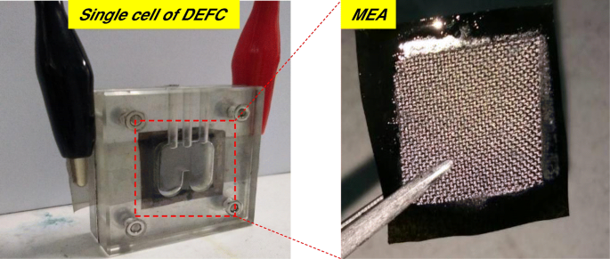
被动碱性电池-DEFC和MEA
结果与讨论
复合膜的特征和形态
季铵化度为 2.6%,其余 97.4% 为 PVA 的基体聚合物 [23]。生产了六种不同类型的膜;原始 PVA 膜、交联 QPVA 膜和四种不同重量百分比的交联 QPVA/GO 复合膜,分别为 5wt.%、10wt.%、15wt.% 和 20wt.%。表 1 列出了原始 PVA 膜和交联 QPVA/GO 15wt.% 复合膜的 EDX 光谱元素映射结果。 PVA复合膜含有碳(C)和氧(O)。同时,交联的 QPVA/GO 15 wt.% 复合膜含有碳 (C)、氮 (N) 和氧 (O),表明季铵基团成功接枝到 PVA 基质中。由于来自 GO 的含氧官能团(羟基、羧基和环氧基团),将 GO 引入 QPVA 会导致复合膜内 O 的重量和原子百分比增加。使用来自 FTIR 分析的振动光谱进一步检查了支持 QPVA 和 GO 参与的证据。 PVA、QPVA 和 QPVA/GO 15 wt.% 复合膜的官能团记录在 400–4000 cm -1 ,如图 3 所示。
<图>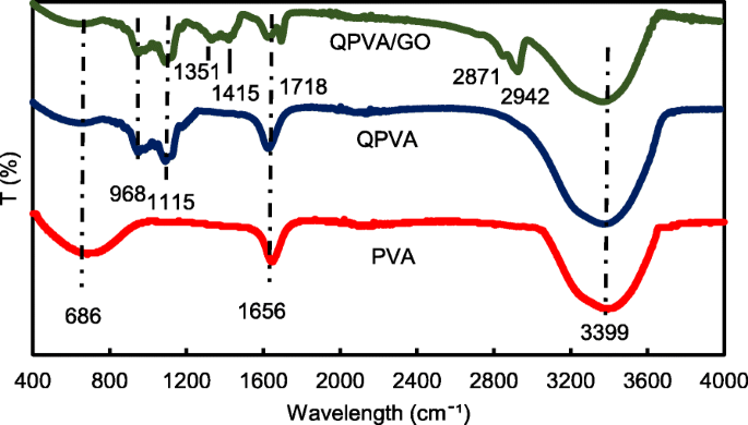
波长为 400–4000 cm −1 的 FTIR 光谱
图 3 显示了从 400 到 4000 cm −1 的波长范围 . 686 cm −1 处的吸收峰 PVA 膜中的 对应于脂肪族 C-H 弯曲 [3]。在季铵化和交联过程之后,脂肪族 C-H 弯曲减少,并且在交联 QPVA 膜和交联 QPVA/GO 15 wt.% 复合膜的光谱中出现了几个新峰。 968 cm −1 处的峰值 被表征为脂肪族C-N,表明季铵基团接枝到基质聚合物的主链上[31];以及 1115 cm −1 处的峰值 表示交联处理后出现的 C-O-C 拉伸基团,证明发生了交联反应,复合膜被 GA 成功交联 [12]。与原始 PVA 和交联 QPVA 相比,复合膜中出现了几个新峰; 1351 cm −1 处的峰值 代表来自 GO [23] 的环氧树脂 C-O 对称振动; 1415 cm −1 处的峰值 表示来自 GO [44] 的羧基 (O=C-O) 的伸缩振动; 1656 cm −1 峰的变形 归因于从对应于 sp 2 的芳香结构延伸的 C=C 的积分 GO疏水区的特征和基质聚合物骨架的反应[39]; 1718 cm −1 处的新峰 由 GO 中羧基中的 -COOH 拉伸引起 [23];新峰出现在复合膜中的 2871 cm -1 ,属于 =C–H 拉伸,在 2942 cm −1 ,可以观察到来自 GO 的 –CH2 的不对称和对称拉伸的增加。 PVA 改性后,在 3399 cm −1 处有强而宽的吸收 可以观察到,由于与 GO 的官能团形成氢键会影响-OH 拉伸的减弱。从 FTIR 光谱分析,PVA 季铵化过程和 GO 合成的峰清楚地显示出与先前研究相似的官能团和疏水区域 [23, 31, 44],这表明交联的 QPVA/GO 复合膜成功合成。
进行X射线衍射测量以观察复合膜的结晶度。 XRD 分析峰的衍射图图示显示在图 4a、b 中。李等人。 [43] 报道了石墨的峰值在 25.6°。图 4a 显示了自制 GO 的 XRD 谱,从石墨到 GO 的相变逐渐发生。由于氧化过程后 GO 的剥离,峰值强度在 10.92° 处略高。这些变化是由于疏水区域与分散在 GO 苯结构边缘的含氧官能团之间的相互作用而发生的 [43]。 XRD 图中 19-20° 处的大峰和 39-40° 处的小峰是 PVA 半结晶结构的指标,如图 4a 所示。由于引入了扰乱 PVA 半结晶结构的铵官能团,QPVA 在 19-20° 处的峰强度与纯 PVA 相比有所降低。因此,无定形区域成为 QPVA 聚合物基质中的域。由于聚合物链中自由体积的增加,该结构有助于提高离子电导率,从而提供更多的自由空间,作为穿过膜的离子路径,聚合物的局部结构松弛和链段运动 [26]。图 4b 显示 GO 的大衍射峰是不可见的,这表明 GO 通过物理相互作用均匀分散在 QPVA 基质中。值得注意的是,2θ =10.92° 处的 GO 峰几乎不可见,因为通过加入 QPVA 聚合物完全剥离和破坏了原始片材。 This result confirmed that the synthesis of a crosslinked QPVA/GO composite membrane involved the formation of hydrogen bonding and the interactions at the ionic level between the polymer chains and the functional groups in GO [23, 39]. The diffraction intensity of the QPVA at 19–20° was still detected, implying that the degree of QPVA crystallinity was maintained until the additional of graphene oxide at 20 wt.% loading. Hence, the chemical structure of the QPVA composite films barely changed as the graphene oxide loading increased, indicating that there were many physical interactions but few chemical reactions occurring between the QPVA and graphene oxide in the composite membrane formation process [39, 48]. In addition, the amorphous structure of composite membrane has significant effect in ionic conductivity due to the formation of free volume by constantly fragmental movement of the polymer matrix. Thus, the presence of GA as a crosslinked and KOH as a doped inside the polymer matrix provided more pathway for ionic to pass through the membrane [27, 49,50,51].
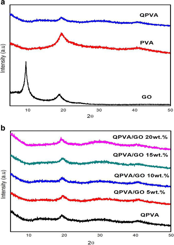
a的XRD图谱 GO, PVA, and QPVA; b QPVA, QPVA/GO composite membrane
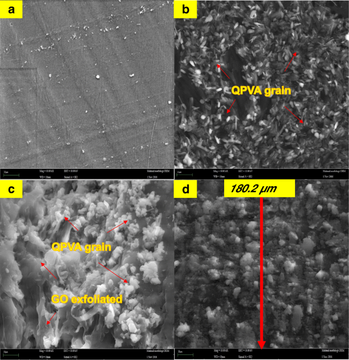
The FESEM, TEM, and AFM images were used to identify the morphological features of GO as shown in Fig. 5. Figure 5a, b shows the FESEM and TEM images which clearly seems that the single layer of graphene oxide (likes a paper sheet) was successfully exfoliated from the graphite flakes. AFM was used to measure GO layer thickness of 0.87 nm as presented in Fig. 5c. The GO thickness obtained has confirm the exfoliated single layer of GO has successfully synthesized. The morphologies of the prepared membrane are shown in Fig. 6a–d by FESEM at a magnification of × 10.00 k. All the top view of FESEM images show that all membranes are dense and remain uncrack, although there are annealing in 100 °C, which proves the excellent chemical stability due to the cross-linkage and modification with GO in QPVA matrix. This characteristic is important for using as polymer electrolyte membrane in DEFC applications, especially to prevent the fuel crossover. The surface of the PVA membrane seems very smooth as shown in Fig. 6a, while the QPVA membrane in Fig. 6b shows a different morphology, as the grain distribution obviously appeared, indicating that the PVA was successfully grafted with quaternary ammonium groups [27]. Figure 6c shows the top view of the QPVA/GO composite membrane, indicating the random distribution of GO inside the QPVA which proved that GO has successfully exfoliated and dispersed throughout the membrane. From the cross-sectional view in Fig. 6d, the composite membrane exhibit a dense and compact structure with high homogeneity, indicating the unification of QPVA and GO in the composite membrane without any holes. In addition, the presence of GA and KOH filled the free volume inside the polymer matrix. This is the important characteristics for separation and fuel crossover reduction. Hence, the homogeneous exfoliation of GO, dispersion of GA and KOH improve the ionic conductivity and reduce the ethanol permeability [23, 24, 52, 53].

FESEM, TEM, and AFM image of exfoliated graphene oxide
FESEM image of a surface PVA membrane, b surface QPVA membrane, c surface of QPVA/GO composite membrane, and d cross section of QPVA/GO composite membrane
Thermal Stability
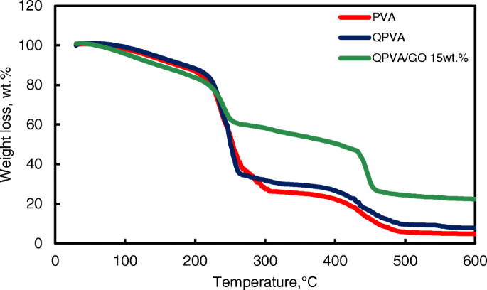
The thermal stability of the crosslinked QPVA/GO composite membrane was illustrated by TGA studies. Figure 7 shows the TGA curves for the pure PVA membrane, QPVA membrane, and QPVA/GO 15 wt.% composite membrane. The TGA curves of these three membranes present three major weight loss regions. The first region is at 70–130 °C due to the loss of adsorbed water in the membrane through the evaporation of the weak and strong physical and chemical bonds of water, respectively. The weight loss of all membranes is approximately 5–8 wt.%. The second transition region of weight loss at approximately 230–320 °C is ascribed to the decomposition of the side chains of the matrix polymers. The weight loss of the membrane was 75 wt.% for PVA, 70 wt.% for QPVA, and 60 wt.% for QPVA/GO; the total weight loss of PVA was the highest due to the presence of fewer side chain groups compared to QPVA/GO. The third transition region of weight loss at approximately 430–480 °C was ascribed to the decomposition of the main chain of the membrane due to cleavage of the C–C backbone of the matrix polymers. At 600 °C, the residual mass of the PVA membrane was 4.7 wt.%. The residual mass of the QPVA membrane and the QPVA/GO membrane were 7.67 wt.% and 22.2 wt.%, respectively.
TGA analysis of PVA membrane, QPVA membrane and QPVA/GO composite membrane
Figure 7 shows that the weight loss of the QPVA/GO 15 wt.% membrane was less than the other membranes; this result indicates that the quaternization process of the PVA matrix and the incorporation of GO inside the composite membranes was successful. The inorganic filler enhanced the thermal stability of the composite membrane and produced a strong network between the matrix polymer and the GO filler reinforcement. In addition, the chemical crosslink reaction by glutaraldehyde assists in the enhancement of thermal stability.
Alkaline Uptake, Swelling Ratio, and Oxidative Stability
Alkaline uptake is the major process for electrolyte preparation. The KOH used for alkaline doping serves as a charge carrier and cross-linker. The alkaline–DEFC was operated with alkaline anode fuel (alcohol in KOH solution). Alkaline uptake in the membrane is important for providing OH − 离子。 The optimal KOH uptake condition is necessary to provide high ionic conductivity. Nevertheless, excessive KOH uptake leads to the deformation of the matrix polymer and degrades the mechanical stability of alkaline–DEFC by shortening its lifetime. The dry membrane films were immersed in 2 M KOH at 30 °C, and the dimensional stability was estimated using the changes of the membrane weight for alkaline uptake and the width, length, and thickness for the swelling ratio of the membrane films before and after doping with 2 M KOH. Table 2 shows that the alkaline uptake of the PVA membrane was 105%. After the quaternization process, the hydrophilic structure C–H and the presence of quaternary ammonium groups led to an alkaline uptake of QPVA membrane increase up to 136%. However, the introduction of GO in QPVA associated the reduction of alkaline uptake until to 45% with 20 wt.% loading of GO. The hydrophobic region of GO contributes a “blocking effect” in the polymer matrix and thus reduced the KOH absorption of the membranes. Furthermore, the crosslinking agent might also reduce the alkaline uptake due to the more compact network structures formed in the composite membranes [23, 50]. The alkaline uptake has influence the swelling behavior of the composite membranes.
<图>The in-plane swelling (i.e., width and length) and through-plane swelling (i.e., thickness) ratios of the composite membranes are shown in Table 2. Generally, a low membrane swelling ratio is favorable for tolerating the dimensional match between the electrode and membrane; thus, the stable formation of MEA is encouraged during single cell performance. The in-plane and through-plane swelling ratios for the QPVA membrane were 18% and 60%, respectively. The introduction of GO up to 20 wt.% loading into QPVA reduced the in-plane and through-plane swelling ratios to 7.54% and 32%, respectively. The introduction of GO not only favors the formation of connected ionic transport channels but also expands the hydrophobic region of GO inside the matrix QPVA, which results in the dimensional stability of the composite membranes [23, 52]. The crosslinked QPVA/GO 20 wt.% composite membrane showed lower swelling ratios than the pristine QPVA membrane.廖等人。 [26] reported a low in-plane swelling ratio due to the strong interactions between the polymer matrix and filler, which involve dipole-dipole interactions, hydrogen bonding, and van der Waals interactions between the polymer and GO. All the samples exhibit good in-plane swelling ratios rather than through-plane swelling ratios, which are beneficial for the MEA contact conditions.
The oxidative stability of the anion exchange membrane was measured in the Fenton’s reagent test which is known as hastened oxidative stability test. Table 1 shows the retained weight percentage of the crosslinked QPVA/GO membranes. After 24-h immersion, the retained weight of the QPVA membrane is 97%. It was slightly declined with increasing of GO loading which retained weight of 91% for 20 wt.% of GO. The obtained results demonstrated that the free radicals have little impact on the QPVA-based membranes due to the greater oxidative resistivity of hydrogen bond formed between GO, GA, and polymer matrix. This may be due to the presence of oxygen contained functional groups present in the GO that easily forms hydrogen bonding with pristine QPVA [1, 23, 54]. The weight loss percentage results indicate that the crosslinked QPVA/GO membrane has good oxidative stability against Fenton’s reagent.
Water Uptake, Ion Exchange Capacity, and Ionic Conductivity
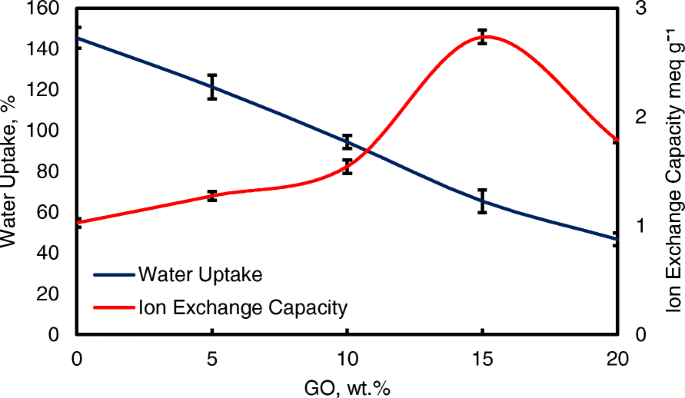
Water uptake is an important parameter for ionic transfer inside the electrolyte membrane. But, higher of water uptake will degrade the membrane performance [8, 50]. From the Fig. 8, the modification of QPVA-based membrane and GO has successfully reduce the water uptake form 145 to 46%. Ion exchange capacity (IEC) is an important parameter for evaluating the mobility ability of anion through the membrane. Besides, IEC is useful to determine the range of optimal water uptake which enhance the conductivity of membrane through the vehicle mechanism [33, 55]. Figure 8 shows that the values of the experimental IEC ranged from 1.05 to 2.71 meq g −1 according to the increase of GO loading. The existence of quaternary ammonium group grafts on matrix polymer and increasing amounts of GO has led to the addition of oxygenic functional groups, including hydroxyl, carboxyl, and epoxy groups, which are useful for anion transfer through the Hopping @ Grotthus mechanisms [22, 35]. Higher IEC values are the main indicator of higher ionic conductivity due to the high charge density inside the membrane [33, 55].
Water uptake and IEC analysis of QPVA membrane and QPVA/GO composite membrane at 30 °C
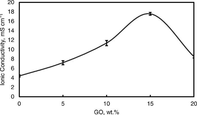
Figure 9 also shows the ionic conductivities of the QPVA membrane and the crosslinked QPVA/GO composite membrane at 30 °C. The ionic conductivity of the QPVA membrane (4.7 × 10 −3 S cm −1 ) is higher compared to the PVA membrane (1.05 × 10 −3 S cm −1 )。 The grafted quaternary ammonium group at the PVA backbone assists in increasing the ionic conductivity due to the OH − that has been transferred effectively through the pathway created by the presence of functional groups in GO [31]. The ionic conductivity of composite membranes was increased which recorded as 7.3 × 10 −3 S cm −1 , 11.3 × 10 −3 S cm −1 , and 17.56 × 10 −3 S cm −1 for GO loading at 5 wt.%, 10 wt.%, and 15 wt.%, respectively. The introduction of GO in the composite membrane up to 10 wt.% showed a slight increase in ionic conductivity attributed to the “blocking effect” of the GO sp 2 characteristic reacting as a hydrophobic region for ionic clusters in the composite membrane.
Ionic conductivity analysis of QPVA membrane and QPVA/GO composite membrane at 30 °C
However, beyond 10 wt.% of GO loading (15 wt.%), the ionic conductivity of the composite membrane increased to 17.35 × 10 −3 S cm −1 due to the sufficiently highly oxygenated functional groups (hydroxyl, carboxyl, and epoxy) in GO to provide alternative anion pathways as well as overwhelming the blocking effect from the hydrophobic region. Thus, the addition of GO has enhance the ionic conductivity of the composite membranes [43]. The oxygenic functional groups of GO, such as carboxyl groups, can form complexes with KOH molecules and form good ionic conductors with high-speed channels for anion exchange and transport. This condition is useful for hopping mechanism [23, 52]. Moreover, the strong interactions between GO, the polymer matrix, and GA form a three-dimensional network that can hold water and alkaline molecules that are important in the Vehicle mechanism. Ionic transport depends on the alkaline molecules and water uptake occurs by the vehicle mechanism. In the composite membranes, the alkaline molecules could be classified as free alkaline and bound alkaline. For conductivity, only the free alkaline affects the anion transport [23, 56]. Figure 10a presents the ionic transport illustration for crosslinked QPVA/GO composite membrane.
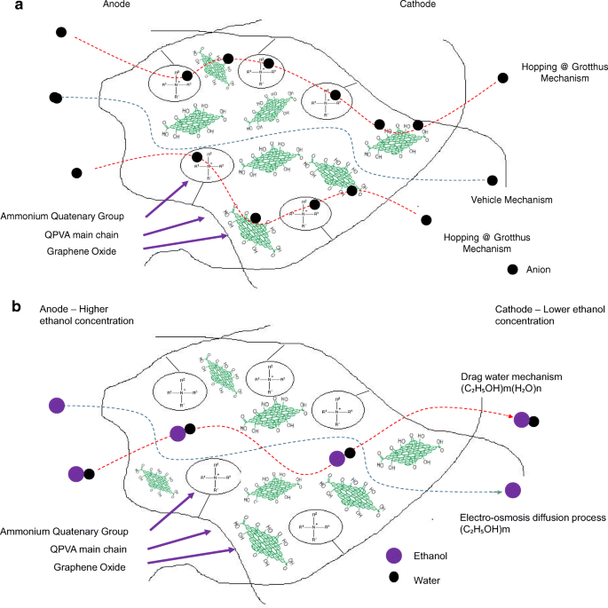
一 Illustration of ionic transfer for the crosslinked QPVA/GO composite membrane. b Illustration of ethanol transfer for the crosslinked QPVA/GO composite membrane
However, when the GO loading exceeded 20 wt.%, the ionic conductivity of the composite membrane declined due to the decrease in alkaline uptake by the composite membrane, which was attributed to the GO hydrophobic region. Hence, this condition disturbs the Grotthuss mechanism in conveying the ionic diffusion, thus reducing the ionic conductivity of the composite membrane. Higher temperature increases the ionic conductivity due to the effect of fast anion mobility. In addition, the distance between the polymer chains becomes larger at higher temperature, providing more free volume and facilitating water molecule movement to enhance anion conductivity [1, 45]. Figure 11 shows the trend of the ionic conductivity when the temperature increased. Increasing temperature also led to increasing ionic conductivity. The highest ionic conductivity was 4.6 × 10 −2 S cm −1 at 60 °C for 15 wt.% GO loading. Compared to the previous study on PVA-based membranes in DEFCs, such as PVA/HPW/DPTA, PVA/TMAPS, PVA/LDH, and PVA/CNTs [11,12,13, 50], the current QPVA/GO membrane showed the highest ionic conductivities.
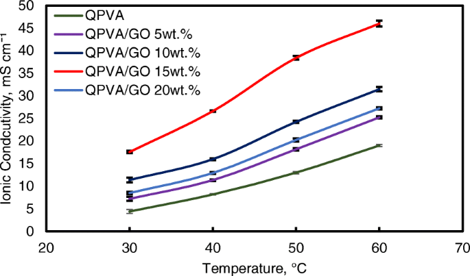
Ionic conductivity analysis of QPVA membrane and QPVA/GO composite membrane at different temperature
The ln σ and 1000/T plots are shown in Fig. 12 with the assumption that the ionic conductivity follows Arrhenius behavior. The activation energy E a of the transferred ion in the composite membranes can be obtained according to the Arrhenius equation:
$$ {E}_a=-b\times R $$ (7)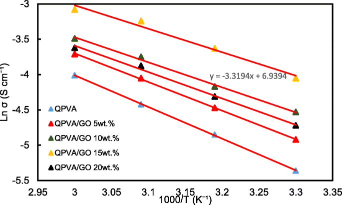
Ln σ vs. 1000/T plot for the QPVA/GO composite membrane; the lines indicate the linear regression
where b is the slope of the regression line for the plotted graph (ln σ vs.1000/T) and R represents the gas constant (8.314472 J K −1 mol −1 )。 The QPVA/GO 15 wt.% composite membrane has the lowest activation energy of 18.11 kJ mol −1 compared to the other composite membranes. The GO loading at 15 wt.% resulted in sufficient presence of functional groups in the composite membrane, also providing an optimal structure for the effective anion transport to subsequently contribute to the reduction of the activation energy.
Ethanol Uptake and Ethanol Permeability
Figure 13 shows the ethanol uptake and ethanol permeability of the pristine QPVA and the crosslinked QPVA/GO (5–20 wt.%) composite membrane in 2 M ethanol at 30 °C. One PVA property is its slight solubility in ethanol, which effectively reduces ethanol crossover [57]. The ethanol uptake clearly indicates that the QPVA polymer absorbs less ethanol than water. With 20 wt.% GO loading, ethanol uptake decreased by ~ 35% (from 52% by the pristine QPVA membrane to 34% by the crosslinked QPVA/GO 20 wt.% composite membrane). This behavior can be explained by the possible appearance of a three-dimensional network built by the crosslinking effect of GA on GO and the polymer matrix. These results are important because they can indicate the dimensional stability of the composite membranes under the set conditions and show their barrier properties and ethanol permeability. The reduction in ethanol uptake was mainly provided from the optimum GO loading, which increased the formation of a three-dimensional network between GA, GO, and PVA. Thus, the free volume of the polymer composite decreased and thus resisted the ethanol mobility pathway [12, 50, 55]. Figure 13 shows similar result of ethanol permeability for the pristine membrane and composite membranes. The ethanol permeability of the membrane decreased by ~ 85% (from 8.7 × 10 −7 厘米 2 s −1 for the pristine membrane to 1.32 × 10 −7 厘米 2 s −1 for the crosslinked QPVA/GO 20 wt.% composite membrane). The reduction of ethanol permeability is affected by increasing the GO content of the composite membrane. The three-dimensional network between GA, GO, and PVA formed a compact structure that increased the resistance of the membrane to ethanol crossover. Besides, the presence of KOH as electrolyte was fulfilled the free volume space in polymer matrix [24, 50, 55]. Figure 10b has illustrated the ethanol transport in crosslinked QPVA/GO composite membrane. The ethanol permeability of the composite membranes has also been studied in different ethanol concentrations (2, 4, 6, and 8 M) at 30 °C, as shown in Fig. 14. The result showed that the ethanol permeability is lower in order of range ~ 10 − 7 厘米 2 s −1 . The reduction in ethanol permeability was attributed to the presence of the hydrophobic region when the GO content increased, which functions as an ethanol crossover blockage [55, 58]. At the same temperature, the crosslinked QPVA/GO composite membrane exhibited lower ethanol permeability than the PVA/phosphotungstic acid solutions, with different percentages of diethylenetriaminepentaacetic acid. The ethanol permeability of the crosslinked QPVA/GO composite membrane is in the range of 1.32–8.7 × 10 −7 厘米 2 s −1 , which is lower than the previous study using QPVA with fume silica (14–16 × 10 −6 厘米 2 s −1 ) in 3 M and 5 M ethanol [40]. The ethanol permeability increased with increasing in ethanol concentration. This result is the initial indicator that the open-circuit voltage of a single cell with this composite membrane will decrease with increasing ethanol concentration.
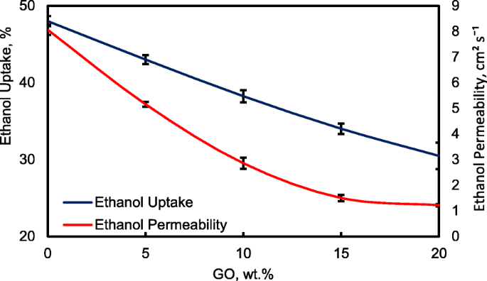
Ethanol uptakes and Ethanol permeability of QPVA membrane and QPVA/GO composite membrane at 30 °C
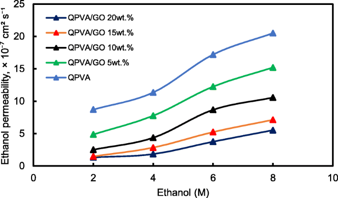
Ethanol permeability of QPVA membrane and QPVA/GO composite membrane with different ethanol concentration
The crosslinked QPVA/GO composite membrane with the highest ionic conductivity (15 wt.% QPVA/GO) at 30 °C was particularly observed in the ethanol permeability test for various temperatures to assess its performance for portable devices in the range of 30 °C to 60 °C, as shown in Fig. 15. The higher temperature leads in higher ethanol permeability due to the interaction between the membrane chains become more active. In addition, the free volume inside the membranes started to extend, which reduced the resistance for ethanol crossover. The diffusion cell was measured in a steady state without any electrical current. When the composite membrane was applied in DEFCs, the practical ethanol permeability was lower due to the movement of anion transport opposite of the direction of ethanol crossover from the anode to the cathode [8, 52].
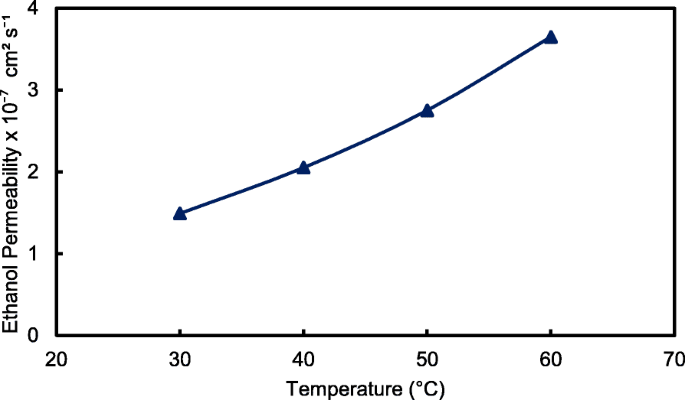
Ethanol permeability of QPVA/GO 15 wt.% composite membrane with different temperature
Selectivity of the Membrane, the Passive Alkaline–DEFC Performance and Durability Test
For the excellent single-cell application of passive alkaline–DEFCs, the membrane should have high ionic conductivity and low ethanol permeability. The ratio of both tests is called the selectivity factor. An excellent performance of a composite membrane is associated with a higher selectivity factor [55]. The selectivity of the composite membranes is presented in Fig. 16. The behavior was caused by the modification of QPVA and the introduction of GO with 15 wt.% loading due to the highest conductivity and the lowest ethanol permeability achieved. Therefore, this membrane has potential for further studies in single-cell alkaline–DEFCs. Table 3 shows a comparison between the ionic conductivity, ethanol permeability, and selectivity factor for PVA-based membranes in passive DEFC applications at 30 °C. The present study shows a comparable performance with the other previous works.
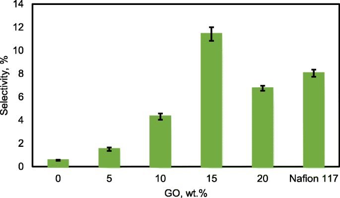
Selectivity of QPVA membrane, QPVA/GO composite membrane and Nafion 117
<图>Figure 17 illustrates the polarization and power density curves for passive alkaline–DEFCs at 30 °C for crosslinked QPVA, crosslinked QPVA/GO 15 wt.%, and Nafion 117 membranes. Obviously, the crosslinked QPVA/GO 15 wt.% composite membrane exhibited a higher open-circuit voltage (OCV) of 0.61 V, which can be attributed to the low ethanol permeability compared to QPVA and Nafion 117, which only reach OCV values of 0.54 V and 0.51 V, respectively. The OCV result was similar with previous study which used the platinum-based catalyst for the single cell test performance, in the range of 0.4 V to 0.6 V [15, 59, 60]. The lower concentration of fuel affected the OCV value, and Yuen et al. [61] reported for the best concentration for passive cell which used platinum catalyst based must be higher than 4 M to achieve the optimum cell performance. The maximum power density of the crosslinked QPVA/GO 15 wt.% composite membrane was 9.1 mW cm −2 , which was higher than QPVA and Nafion 117 of 5.88 mW cm −2 and 7.68 mW cm −2 , respectively. These results prove that the interaction between QPVA and GO occurred and was powerful to improve the potential of these membranes.
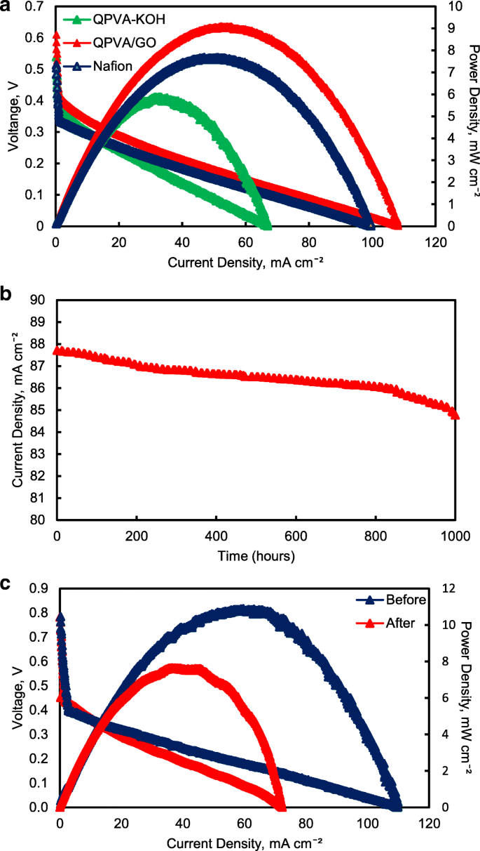
一 Cell voltage and power density vs. current density curve obtained for the passive alkaline–DEFC. b Durability test on passive alkaline–DEFC. c Cell voltage and power density vs. current density curve before and after 10,000 min of durability test. Anode feed; 2 M KOH + 2 M ethanol, vathode feed; Air:a at 30 °C; b , c at 60 °C
The performance of cell current density throughout the durability test operation at 60 °C was shown in Fig. 17b. The passive alkaline–DEFC was operated for 1000 h at a constant voltage of 0.3 V continuously. The current density of cells start with 87.7 mA cm −2 and was decreased continuous slowly until 1000 h operation and finally reaching approximately 84.7 mA cm −2 at 1000 h. This performance decreased steadily may be caused by the increasing of ethanol permeability which attributed the enhancement of fuel crossover without oxidation activity, which was significant negative effect on single cell performance [62]. The durability test results show high efficiency operation of crosslinked QPVA/GO 15 wt.% composite membrane in single cell which the sustainable performance until 1000 h.
Figure 17c shows the change of performance in cell voltage and power density of the crosslinked QPVA/GO 15 wt.% composite membrane before and after durability testing to evaluate the permanent degradation of alkaline passive–DEFC. When the operation temperature of single cell increase 60 °C, the OCV of cell increase to 0.78 V and the maximum power density of the crosslinked QPVA/GO 15 wt.% composite membrane increase 11.4 mW cm −2 . After the durability testing, the maximum power density reduced to 7.65 mW cm −2 . The dropped of power density was subjected to activation loss of catalyst activity due to ethanol crossover and the loss of maximum power density was 32.8%. The power loss depended on the current density drawn from the single cell. However, the value of OCV after the 1000 h test presented no significant reduction compared to before durability test [63].
Table 3 presents a comparison of PVA-based membranes previous study applied in passive DEFCs using a Pt-based catalyst. The performance in this study was higher than that of the passive DEFCs reported by Yang et al. [14] (8 mW cm −2 ) and higher than the optimization of commercial Nafion®117 membranes in passive DEFCs reported by Pereira et al. [5] (1.33 mW cm −2 )。 This result demonstrated the success of our study targeting the performance of passive alkaline–DEFCs using crosslinked QPVA/GO composite membrane as alternative membrane for commercial membrane.
Conclusion
New composite membrane was prepared by blending the QPVA polymer as a matrix and GO as a filler using GA as a crosslinking agent. The existence of a quaternary ammonium group grafted on PVA and modified with GO was confirmed by FTIR, XRD, and FESEM-EDX analysis. With the formation of three-dimensional networking between the polymer matrix, GO, and the crosslinking agent, the thermal stability of the composite membrane was enhanced. The highest ionic conductivity achieved was 0.046 S cm −1 , along with a low ethanol permeability of 1.48 × 10 7 厘米 2 s −1 . The maximum power density of 9.1 mW cm −2 was observed for the crosslinked QPVA/GO 15 wt.% composite membrane at 30 °C and 11.4 mW cm −2 at 60 °C. Therefore, the crosslinked QPVA/GO composite membrane has high potential for use in single-cell DEFC applications. The process of optimizing the composition of QPVA/GO and the replacement of the non-Pt catalyst are expected to further enhance the performance of the QPVA/GO composite membrane.
缩写
- A:
-
Membrane
- 原子力显微镜:
-
原子力显微镜
- C:
-
Carbon
- Ca:
-
Concentration of the feeding chamber in cell A
- DEFC:
-
Ethanol fuel cell
- EDX:
-
能量色散X射线光谱
- FESEM:
-
Field emission scanning electron microscope
- GO:
-
Graphene oxide
- GTMAC:
-
Glycidyltrimethyl-ammonium chloride
- H2O2 :
-
Hydrogen peroxide
- H2SO4 :
-
Sulfuric acid
- H3PO4 :
-
Phosphoric acid
- HCL:
-
Hydrochloric acid,
- KOH:
-
Potassium hydroxide
- L:
-
Distance between the counter electrodes
- L:
-
Thickness of the membrane
- m:
-
Mass (g) of the dried composite membrane.
- Ma :
-
HCl required after equilibrium
- Mb :
-
HCl required before equilibrium
- N:
-
Nitrogen
- NaOH:
-
Sodium hydroxide
- O:
-
Oxygen
- P:
-
Ethanol diffusion permeability of the membrane
- PVA:
-
Poly (vinyl alcohol)
- QPVA/GO quaternized:
-
Poly (vinyl alcohol)/graphene oxide
- R:
-
Resistance of the membranes
- t wet :
-
Thickness
- TEM:
-
透射电子显微镜
- TGA:
-
Thermogravimetric analysis
- Vb:
-
Volume in each of the diffusion reservoirs
- XRD:
-
X射线衍射
- σ:
-
Proton conductivity
纳米材料
- 钛酸盐纳米管装饰氧化石墨烯纳米复合材料:制备、阻燃和光降解
- 水对微晶和纳米纤维素结构和介电性能的影响
- 石墨烯和氧化石墨烯的体外和体内生物安全和抗菌能力
- 氧化石墨烯杂交 nHAC/PLGA 支架促进 MC3T3-E1 细胞的增殖
- 石墨烯/WO3 和石墨烯/CeO x 结构作为超级电容器应用电极的评估
- 用于 CCRF-CEM 开启检测的基于氧化石墨烯的荧光适体传感器
- 通过海藻酸钠电解质-磺化氧化石墨烯生物膜增强质子电导率和降低甲醇渗透率
- 囊泡和细胞的调频波介电泳:以交叉频率周期性 U 形转弯
- 氧化石墨烯的低温还原:电导率和扫描开尔文探针力显微镜
- 用于高性能超级电容器的阴离子表面活性剂/离子液体插层还原氧化石墨烯
- 形态和晶体结构对二氧化钛纳米管热导率的影响
- 氢燃料电池是交通的未来吗?


