

一步合成基于壳聚糖的三组分系统用于药物释放的氮掺杂亲水性介孔碳
摘要
具有不同碳硅(C/Si)比(NMCs-x)的原位氮掺杂亲水介孔碳球 /3, x =5, 6, 7, 8) 是通过一步法结合喷雾干燥和碳化技术制备的,其中使用三嵌段共聚物 (F127) 和原硅酸四乙酯 (TEOS) 作为模板剂,以及生物相容性壳聚糖 (CS )用作碳源和氮源。这些碳材料通过 TG、BET、XRD、拉曼、FTIR、TEM、XPS 和接触角测量仪进行了表征。研究了介孔碳材料对难溶性抗肿瘤药物羟基喜树碱(HCPT)的吸附和释放特性。结果表明,成功制备了具有高比表面积(2061.6 m 2 /g)、狭窄的孔径分布 (2.01–3.65 nm) 和高氮含量 (4.75–6.04%)。那些 NMC-x 表现出令人满意的亲水性,并随着表面 N 含量的增加而逐渐增加。而NMCs的亲水性更好-x 是,HCPT 的吸附容量更大。 NMCs的吸收能力-x HCPT 的顺序如下:q NMCs-5/3 > q NMCs-6/3 > q NMCs-7/3 > q NMCs-8/3。 NMCs-5/3对HCPT的饱和吸附容量最大(1013.51 mg g -1 )和更高的溶出率(93.75%)。
介绍
介孔二氧化硅[1, 2]、介孔分子筛[3]、介孔碳[4,5,6]等材料已广泛应用于生物医学领域。其中,介孔碳材料在比表面积、孔容、化学稳定性和热稳定性等方面具有较好的性能[7],更适合作为优良的载药材料。据报道,介孔碳材料已广泛应用于抗肿瘤载药(喜树碱[8]、阿霉素[9,10,11,12]、紫杉醇[13,14,15,16]、光热疗法、综合疗法、荧光细胞标记、人体有毒物质的生物吸附、医学成像和生物传感[17]。
目前,酚醛树脂 [18, 19] 和蔗糖 [20, 21] 通常被用作碳源来制备介孔碳。然而,作为碳源的酚醛树脂存在潜在的环境危害。此外,蔗糖还具有制备工艺复杂、成本高的缺点。这两种碳源材料制备的介孔碳材料亲水性较差,制约了介孔碳作为药物装载剂在注射剂和血液循环中的应用[17]。为了增加介孔碳的亲水性,已经提出了许多方法来通过混合酸氧化[9,12,22]或在介孔碳材料上直接掺杂氮来改性介孔碳[23,24,25]。然而,强氧化可能会对介孔碳的表面性质和孔结构产生负面影响,从而影响其载药潜力。另一方面,处理后的氮掺杂繁琐且成本高,不适合量产。
壳聚糖是一种具有丰富碳含量、羟基(-OH)和氨基(-NH2)的生物质[26, 27]。以壳聚糖为碳源制备介孔碳材料。
目前,已经报道了壳聚糖作为碳源通过蒸发诱导自组装(EISA)方法制备介孔碳。例如,Sun[28]制备了孔径为2-16 nm、比表面积为293-927 m 2 的介孔碳 /g 使用壳聚糖-质子盐作为碳源和 F127 作为模板。冯[29]制备了孔径为5~15 nm、比表面积为41~457 m 2 的介孔碳 /g 使用壳聚糖作为碳源和 F127 作为模板。 Andrzej [30] 制备了孔径为3-20 nm、比表面积为600-1337 m 2 的介孔碳 /g 使用壳聚糖作为碳源和胶体 SiO2 作为模板。然而,这些制备的介孔碳材料具有更宽的孔径分布、更低的比表面积、不规则的形态和更大的粒径(> 1 μm)。常用抗癌药物的分子大小通常在1.1-1.9 nm范围内,如紫杉醇、多柔比星和羟基喜树碱(HCPT),分别为1.90 nm × 1.19 nm × 0.07 nm、1.52 nm × 1.08 nm × 0.71 nm,分别为 1.14 nm × 0.69 nm × 0.44 nm(由 Materials Studio 软件计算)。一般来说,多孔材料较窄的孔径分布有利于吸附质分子的传质,多孔材料的合适孔径为吸附质分子尺寸的1.5~3.0倍[31]。因此,作为药物载体的介孔碳材料应具有窄孔径、大体积、高比表面积、良好的生物相容性和亲水性以及纳米球形形态。在我们之前的报道中,直径小于 1 μm 的球形介孔碳是通过喷雾干燥技术制备的 [32]。然而,虽然制备的介孔碳材料表现出更高的亲水性(接触角θ为124.1 o ) 比以蔗糖为碳源制备的样品 (接触角θ为 161.9 o ),由于含氧基团较少,介孔碳前驱体在碳化过程中形成的有机骨架严重收缩和坍塌,导致介孔碳的亲水性和比表面积仍不理想。据报道,原硅酸四乙酯(TEOS)在酸性溶液中水解缩聚可产生富含硅羟基的硅酸聚集体,通过氢键与F127亲水链段的醚键连接[33],可防止其收缩和坍塌。碳化过程中的碳结构[18],增加介孔碳材料的含氧基团。
本文以壳聚糖为碳源和氮源,以F127和TEOS为模板,采用喷雾干燥结合碳化技术制备具有球形形态的亲水性纳米介孔碳材料。考察了不同碳硅比 (C/Si) 对 NMCs 孔结构、组成和亲水性能的影响,以及介孔碳材料对难溶性抗肿瘤药物羟基喜树碱 (HCPT) 的吸附和释放性能进行了调查。
材料和方法
原材料和试剂
两亲性三嵌段共聚物 F127 (M w =12,600,EO106-PO70-EO106,Sigma-Aldrich,美国),TEOS(美国阿拉丁试剂公司),CS(脱乙酰度≥95%,粘度100~200 mPa·s;美国阿拉丁试剂公司),HCPT( HCPT-160201;成都元成生物科技有限公司,中国)和冰醋酸、盐酸、无水乙醇、吐温80、磷酸二氢钾和氢氧化钠(分析纯;上海国药化学试剂有限公司) , 中国) 被使用。所有实验均使用去离子水。
NMC 的准备
掺氮介孔碳的制备可通过图1的合成示意图来描述。有四个步骤:(I)以壳聚糖为碳源和氮源,三嵌段共聚物F127和原硅酸四乙酯(TEOS)为模板代理。在醇-水双相体系中,通过 F127 和 TEOS 之间的双电子耦合形成球形胶束。然后水解形成Si-OH,CS中的-NH2在酸性条件下形成氢键,形成三元体系,随后聚合交联形成络合物; (II)复合材料的喷涂成型由三组分体系通过喷雾干燥工艺组装而成; (III)在氮气氛中焙烧和碳化去除F127; (IV)热碱脱硅以形成介孔碳材料。制备了四个具有不同 C/Si 比的代表性样品,并标记为 NMCs-5/3、NMCs-6/3、NMCs-7/3 和 NMCs-8/3。一个典型的合成实验包括以下步骤: (a) CS 溶液的制备——将 CS(7.0、8.4、9.8 或 11.2 g)溶解在 5% 的醋酸水溶液中,在 40 °C 下制备 2.1% 的 CS 溶液. (b) 在 40 °C 下将 2.1 g F127 溶解在 50 mL 乙醇溶液中,然后加入 15.6 mL TEOS 和 0.2 M HCl (15 mL) 进行水解,从而制备 NMC。反应10分钟后,将溶液转移到CS溶液中并混合60分钟。然后将混合物在室温下静置 60 分钟,然后用喷雾干燥器(BUCHI B-290,BUCHI,瑞士)在 170 °C 的入口空气温度和 3.5 mL/min 的进料流速下干燥。所得样品标记为CS/SiO2/F127; (c) 碳化过程——将 CS/SiO2/F127 粉末置于管式炉中,氮气流量为 200 cm 3 /h,并以 2 °C/min 的速率加热至 410 °C。然后保持该温度 2 小时,然后以 5°C/min 的速率升高至 900°C,并煅烧 2 小时以获得 C-Si 复合材料。使用热碱和 1 M NaOH 水溶液在 85 °C 下从获得的 C-Si 复合材料中去除 Si 两次,用去离子水洗涤直至获得中性 pH 读数,然后在 100 °C 下干燥,得到介孔碳(图。1)。所得材料根据溶液中 CS 的用量(7.0、8.4、9.8 或 11.2 g)分别标记为 NMCs-5/3、NMCs-6/3、NMCs-7/3 和 NMCs-8/3 CS,分别)。
<图片>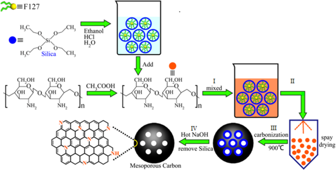
NMCs制备过程示意图
表征方法
使用Micrometrics ASAP2020 N2吸附/解吸物理吸附仪测试介孔碳的比表面积、孔体积和孔径。样品在真空条件(76 mmHg)下在 120°C 下预脱气 12 小时。比表面积(S BET) 使用 Barrett-Emmer-Teller 方法计算,而孔体积 (V BJH) 和孔径 (D BJH) 使用 Barrett-Joyner-Halanda (BJH) 模型计算,其中孔体积计算为相对压力下的吸收能力 P /P 0 =0.975。
使用ElementarVario EL III型元素分析仪对NMCs的元素组成(C、H、O、N)进行表征。
F127、CS 和三元系统喷雾中间产物 CS/SiO2/F127 的热解过程使用 Netzsch STA 449C 热分析仪进行表征。温度范围设置为从室温到 1000 ℃,速率为 5 ℃/min。
NMCs的晶体特性使用Bruker D8 Advance X射线衍射仪进行表征,CuKα辐射,入射波长λ 0.154060 nm,在 40.0 kV 和 40.0 mA,以及 2θ 0.9-4°范围(扫描速度:0.5°/min,扫描步长0.002°)。
采用FEI Tecnai G2 F20 S-Twin透射电子显微镜在200 kV加速电压下分析介孔碳的形貌。
NMC 的原子结合状态使用 ThermoScienfticEscalab 250XI X 射线光电子能谱仪使用 Al Kα 辐射源和以下参数进行表征:测试能量,1486.8 eV;测试光斑直径,500 μm;试管电压,15 kV;管电流,10 mA;分析室极限压力,2 × 10 –9 毫巴。根据C1s在284.8 eV处进行峰位校正。
使用Dataphysics OCA25光学接触角测量仪测试样品表面的水接触角。
HCPT 在 NMC 上的吸收
HCPT 准确称取至 10 mg,溶于 50 mL 无水乙醇溶液,配制成 200 μg/mL 的标准储备液。然后,将储备溶液稀释至浓度(0.4、0.5、1、3、5、7 和 10 μg mL –1 )。以无水乙醇溶液为参比溶液,采用紫外分光光度法在385 nm处测定各浓度标准溶液的吸光度值。进行质量浓度(C)与吸光度(A)的回归分析,得到回归方程y =0.07573x + 0.04149;标准曲线在0.4~10 μg/mL的测定范围内吸光度与浓度呈良好的线性关系,相关系数R 2 =0.99947。
用有机溶剂浸渍溶液的方法将药物加载到 NMCs 中。 HCPT 溶液 (0.2~1.2 mg mL –1 ) 是通过将一定量 (6~36 mg) 的 HCPT 溶解在 30 mL 无水乙醇中制备的。随后,加入20mg各种NMC,在37℃水浴中避光混合24h,8000r/min离心10min分离。然后提取上清液,通过紫外吸收光谱法在最大吸收波长 385 nm 处检测 HCPT 的浓度。将载药体置于真空干燥区,40 °C 放置 24 h。根据吸附前后浓度的变化确定吸附在 NMC 样品上的药物量。各NMC样品的药物吸附量按下式计算:
$$ \mathrm{Drug}\ \mathrm{adsorption}\ \mathrm{capacity}\left(\mathrm{mg}/\mathrm{g}\right)=\frac{\mathrm{Drug}\ \mathrm{content }\ \mathrm{in}\ \mathrm{NMCs}}{\mathrm{Amount}\ \mathrm{of}\ \mathrm{NMCs}} $$HCPT 药物释放
动态透析用于检测 15 mg 纯 HCPT 以及载药 NMC(NMCs-5/3@HCPT、NMCs-6/3@HCPT、NMCs-7/3@HCPT 和 NMCs)的药物溶出度-8/3@HCPT)。在 37 °C 下,在 pH 7.4 和 pH 5.0 以及 0.1% Tween-80 的磷酸盐缓冲溶液 (PBS) 中,在黑暗中进行体外释放测试。将制备好的PBS缓冲液-NMC样品溶液(pH 7.4和pH 5.0)放入透析袋(MWCO =14,000)中,浸入500 mL pH 7.4、pH 5.0的PBS中,37°C下以100 r/min搅拌.以 1、2、4、6、8、10 和 12 小时的固定时间间隔取回 4 mL 等分试样,并补充新鲜的等温、等容 PBS。提取透析液,8000 r/min离心10 min;提取 1 mL 上清液,稀释 20 倍,用紫外分光光度法在 385 nm 处测定其吸光度。根据标准曲线计算药物浓度,HCPT的累积释放量按下式计算:
$$ Q\left(\%\right)=\frac{V_1{C}_n+{V}_2\sum {C}_{n-1}}{W}\times 100\% $$其中 V 1 是培养基体积(mL),V 2 是采样体积(mL),C n 是n中HCPT的样品浓度 次采样,(μg mL –1 ), n 是抽样试验的次数,W 是 NMCs 中 HCPT 的药物含量。
结果与讨论
碳化条件的测定
图 2a 显示了游离模板剂 F127、CS 和 CS/SiO2/F127 复合材料的热重 (TG) 曲线。可以看出,F127 在 400°C 时几乎完全热解 [34],重量损失约为 99.6%,而 CS 在 250-400°C 时经历了 56% 的重量损失,随后在 400-900°C 达到平台期C(800–900 °C 时重量损失 1.53%),表明碳骨架在 800 °C 时形成。 CS/SiO2/F127 的失重主要发生在 500 °C 以下(55.5%),主要是由于 F127 和 CS 的热解;高于 800 °C,TG 曲线趋于平稳,表明 CS 几乎完全碳化。 Andrzej [30] 指出,在高碳化温度(1000-1100 °C)下,材料的氮含量降低。因此,400 ℃保温2 h去除F127,900 ℃保温3 h以保证碳材料具有较高的氮含量和石墨化程度。
<图片>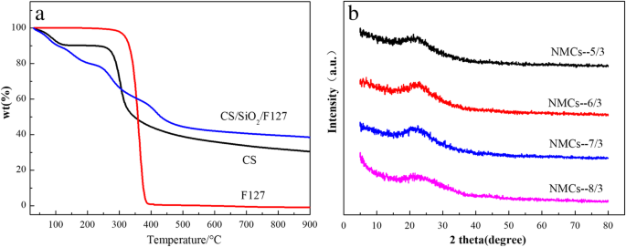
一 CS、F127 和 CS/SiO2/F127 的 TG 曲线。在氮气流下加热速率为5℃/min。 b NMCs-x的NMCs的XRD图谱 /3(x =5,6,7,8)
C/Si 对介孔碳的影响
介孔碳的 XRD 分析
制备的样品NMCs-x的XRD谱 /3(x =5,6,7,8) 如图 2b 所示。在 2θ 处有一个宽峰 =23° 在四个制备的样品上,这是无定形碳材料的典型特征峰 [35]。可以看出制备的碳材料NMCs-x /3具有无定形结构,与参考文献[36, 37]报道的结果一致。
介孔碳的孔结构分析
绘制了四种NMC样品的N2等温吸解吸曲线及其孔径分布曲线(图3);相关孔结构数据见表1。P后 /P 0 ≥ 0.4,四个样品的 N2 吸附等温线显示出典型的介孔碳材料的滞后回线 [38, 39];从四个样品中,NMCs-7/3 的滞后回线最大(图 3a)。孔径分布图显示碳材料的孔径分布较窄,主要在2.01~3.65 nm(图3b),相当于HCPT空气动力学当量直径的1.75~3.2倍。 Kondo 认为 [31] 孔径越小,吸附质进入孔隙的扩散速度越慢;孔径越大,被吸附物和固体表面的吸附势将导致固体表面吸附不良。当孔径为吸附质空气动力学当量直径的1.5~3.0倍时,吸附能力最佳。因此,本文制备的介孔碳的孔径适合于HCPT的吸收。
<图片>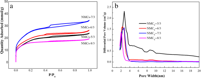
N2 吸附-解吸等温线 (a ) 和孔径分布曲线 (b ) 的 NMCS
孔结构数据(表1)表明,随着C/Si比的增加,NMC-x材料的介孔孔体积和BET比表面积先增大后减小,在C/Si=7:3时达到最大值。这可以归因于以下机制。在低 C/Si 比(5/3)时,CS 上的 –OH 和 –NH2 的量也很少,而 TEOS 的量相对较大;因此,TEOS水解和缩聚形成的Si-OH量也很大,因此与CS上的-OH和-NH2发生氢键不足,导致三维交联网络结构的溶胶减少.随后,在去除 TEOS 和 F127 模板后,介孔孔体积减少。此外,由于存在过量的 TEOS,形成的胶束很大,去除 TEOS 后获得的平均孔径也很大。相反,在高 CS 含量下,因此高 C/Si 比(8/3),CS 提供更多的 -OH 和 -NH2,使得 TEOS 水解和缩聚形成的 Si-OH 不足,导致形成更小和更少的胶束,降低中孔碳的孔体积和孔径。显然,在 C/Si 比为 7:3 时,可用的 -OH 和 -NH2 基团与 TEOS 上的 Si-OH 量很好地匹配,导致形成更大的介孔孔体积和 BET 比表面积.
介孔碳的 TEM 分析
由于NMC-7/3具有最大的比表面积和介孔体积,因此仅对该样品进行了进一步的孔分布和微观结构测试,数据如图4所示。 TEM图像表明制备的介孔碳材料NMC-7/3在不同放大倍数下均呈球形结构,粒径均在1 μm以下(图4a、b)。粒径约为 200 nm 的介孔碳材料可以有效地携带药物通过细胞膜,从而发挥一些独特的治疗功能[40]。图 4c 显示样品的孔隙结构可见,呈现清晰典型的蠕虫状结构 [34](图 4c)。可以看出,在介孔碳颗粒的边缘可以观察到~2nm的孔道,这是由壳聚糖的链状结构的碳化和重组以及模板的去除所产生的。然而,在颗粒表面观察到的小白点的大小一般小于2 nm,这是由于壳聚糖碳化形成的链的重叠和交织所致。
<图片>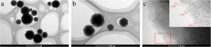
一 –c NMCs-7/3不同放大倍数的TEM图
成分和亲水性分析
NMCs的组成分析
介孔碳材料NMCs-x的FTIR光谱 /3如图5a所示; 3430 厘米 −1 是 N–H 和 O–H 的伸缩振动吸收峰 [41], 1630 cm -1 是C=N和C=C的伸缩振动吸收峰,1120 cm −1 是C-N和C-C的伸缩振动吸收峰,表明氮原子成功掺入到NMCs中。
<图片>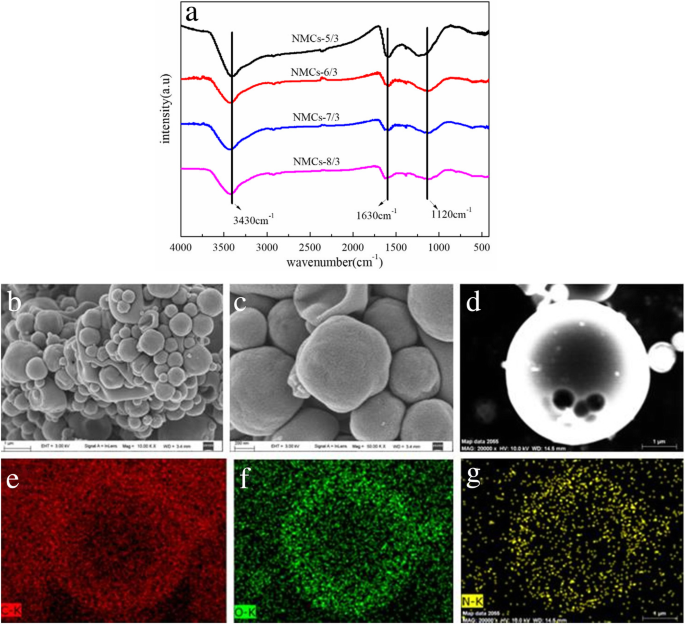
FTIR(a ) NMC 的 NMC 模式-x /3(x =5,6,7,8); SEM 图像 (b –d ) 的示例 NMCS-7/3 和元素映射 (e –g ) 瞄准 SEM 图像插图中的球体 (d ),它响应元素 C、O 和 N , 分别。
NMC-7/3 的 SEM(图 5b-d)及其表面的 C(e)、O(f) 和 N(g) 元素分析(图 5e-g)清楚地表明介孔碳制备的材料为球形,但其尺寸不均匀。这是由于喷雾干燥过程。元素扫描数据表明C、O和N元素分布在纳米球介孔碳内。因此,N 成功掺杂到NMCs中。
四个 NMC 的 XPS 图如图 6 所示,表明四个样品含有 O、N 和 C(图 6a)。 N1s 用峰分化和拟合处理(图 6b-e),显示 N1s 分裂成四个峰,相应的结合能分别为 398.37、400.80、402.40 和 404.53 eV,归因于吡啶氮(N-6) 、吡咯氮 (N-5)、季氮 (NQ) 和氧化 -N (N-O) [36, 42,43,44,45]。此外,N-5 和 N-6 的峰面积更大,表明复合材料中的含量更大。这些结果清楚地表明原位 N 以吡啶氮和吡咯氮的形式掺杂到介孔碳中。
<图片>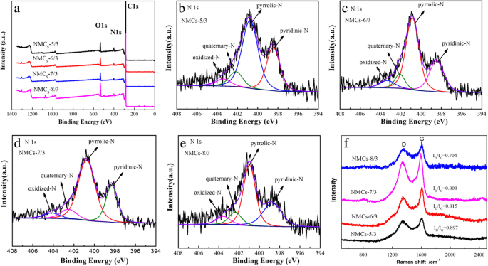
NMC 的 XPS 调查 (a ) 和 NMCS-5/3 (b ), NMCs-6/3 (c ), NMCs-7/3 (d ), NMCs-8/3 (e )。拉曼(f ) NMC 的 NMC 模式-x /3(x =5、6、7 和 8)
表 2 显示了通过 XPS 和元素分析获得的四种 NMCs 表面的 C、N 和 O 含量(每种技术检测到的元素含量差异有细微差别)。总N NMCs-5/3 的 NMCs 表面含量最大,其次是 NMCs-6/3、NMCs-7/3,最后是 NMCs-8/3。因此,随着 C/Si 比的增加,NMCs 表面的 N 含量逐渐降低。这种现象归因于这样一个事实,即在较低的 C/Si 比率下,系统中 Si-OH 的数量越多,CS 上可用于氢键的 –OH 和 –NH2 的数量就越少。因此,-NH2 与形成的三维网状结构中强的 Si-OH 接触的机会更多,它们之间的结合力更强,导致在煅烧过程中碳骨架中残留的 N 量更高。然而,在较高的 C/Si 比下,CS 上的 –OH 和 –NH2 不能通过与 TEOS 水解形成三维网络结构,因此在煅烧过程中由于挥发到 N 气氛中而保留的 N 较少。
碳材料NMCs-x的拉曼光谱 /3如图6f所示。所有样品均在 1350 cm -1 处出现两个明显的特征峰 和 1601 厘米 −1 , 对应于 D 和 G 分别为碳材料的峰。其中,D 峰值反映了原子位移、无序碳、边缘缺陷和其他缺陷的程度(sp 3 碳材料中的碳、悬空碳和空位等),以及G peak 反映了 sp 2 的有序程度 碳。 D 的比率 达到 G 的峰值 峰值 (I D /我 G )可以反映碳材料的结晶程度[46]。指出I的顺序 D /我 G 值与 N 相同 随着氮含量的增加,其表面会产生更多的缺陷[47]。计算结果表明,I D /我 G 四种碳材料NMCs-5/3、NMCs-6/3、NMCs-7/3和NMCs-8/3中的分别为0.897、0.815、0.808和0.704,其尺寸大小顺序为氮含量相同(见表 2)。可以看出,较大的I D /我 G NMCs-5/3的值表明结构缺陷更明显,这是由于碳材料上掺杂了大量的氮所致。
NMC 的亲水性
水在 NMCs-5/3、NMCs-6/3、NMCs-7/3 和 NMCs-8/3 上的动态接触角每 0.1 秒(图 7a-e)、0.3 秒(图 7f-)测量一次j)、0.4 s(图 7k-o)和 0.7 s(图 7p-t)表明降低 NMCs-5/3、NMCs-6/3、NMCs-上的水滴接触角所需的时间7/3 和 NMCs-8/3 到 20°以下分别为 0.45 s、1.15 s、1.54 s 和 2.71 s。因此,与未掺杂氮的介孔碳对应物 (129°) 相比,这四个样品显示出强亲水性 [37]。 NMCs中的氮元素形成活性位点,导致sp 2 增加 簇分数,提高了碳材料的表面粗糙度 [48],因此,更小的润湿角和增强的亲水性和分散性。此外,NMC 中 N-5、N-6 和水分子之间的氢键也导致亲水性增强 [23, 49, 50]。这些效应的耦合使得NMCs在药物递送中的潜在应用成为可能。
<图片>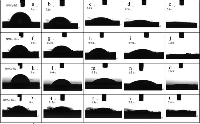
作为接触时间函数的介孔碳表面水接触角的光学显微照片 (a –e ) NMCs-5/3, (f –j ) NMCs-6/3, (k –o ) NMCs-7/3, 和 (p –t ) NMCs-8/3
图 8 是这四种 NMC 接触角随时间变化的关系曲线。如图 8 所示,将 NMCs-5/3、NMCs-6/3、NMCs-7/3 和 NMCs-8/3 上的水滴接触角降低到 20°以下所需的时间为 0.45 s、1.15 秒、1.54 秒和 2.71 秒。实现相同接触角所需的时间越短,样品的亲水性越好。显然,每个 NMCs 的亲水性可以按照 NMCs-5/3> NMCs-6/3> NMCs-7/3> NMCs-8/3 的降序排列,这与 N 的含量一致在介孔碳上。换句话说,NMCs-5/3上N含量最高意味着亲水性最好。这可以归因于介孔碳材料上N含量越高,表面粗糙度越大;此外,N-5和N-6的含量较高也导致NMC与水分子之间的氢键增强;这两种耦合效应增强了NMCs的亲水性,可以解释为什么接触时间最短。
<图片>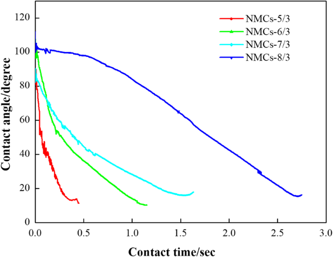
Plots of water contact angle on different mesoporous carbon versus contact time
Evaluation of Adsorption and Release Properties of NMCs for HCPT
The HCPT adsorption curve of the four NMCs showed a gradually increasing adsorption capacity with increasing concentration of HCPT solution (Fig. 9a). This is attributed to the fact that the absorption and diffusion of HCPT in porous materials is based on the concentration gradient principle, wherein the higher the concentration of HCPT, the stronger the concentration gradient propulsion, and the greater the amount of HCPT arriving at the adsorption sites on the surface of NMCs for adsorptive preconcentration will be higher.

一 HCPT adsorption isotherms of NMCs-x (x =5, 6, 7, and 8) in ethanol solution. b The XRD patterns of pure HCPT and NMCs-x /3(x =5, 6, 7, and 8)@HCPT. In vitro release profiles of HCPT from NMCS-x (x =5, 6, 7, and 8)@HCPT and pure drug in pH =7.4 (c ) and pH =5.0 (d ) PBS solution
The experimental data retrieved from Fig. 9a was fitted using the Langmuir model (the processed data is provided in Table 3) using the Langmuir adsorption model equation, as follows:
$$ q={K}_L{q}_mc/\left(1+{K}_Lc\right) $$其中 q is the mass of HCPT adsorbed in the porous structure per unit mass of NMCs at the equilibrium state(mg g −1 ), q 米 is the saturated adsorption capacity of NMCs for HCPT(mg g −1 ), c is the concentration of HCPT at the equilibrium state of adsorption (mg mL −1 ), and K L is the Langmuir adsorption constant (mg g min −1 ).
The adsorption of HCPT molecules in the porous structure of NMCs followed the Langmuir’s adsorption law. Additionally, the value of the absorption constant did not vary significantly, suggesting that the affinity for HCPT was similar among the four NMCs. Notably, the absorption capacity of all four NMCs for HCPT is higher, up to 1013.51 mg g −1 (50.33% drug loading), which is much higher than that of the non-N-doped three-dimensional macroporous carbon material (24% drug loading) for HCPT [51]. However, the absorption capacity of the four NMCs for HCPT is higher for NMC-5/3, followed by NMC-6/3, NMC-7/3, and, finally, NMC-8/3, in line with the order of the content of N on the surface of mesoporous carbons. Thus, the higher the N content on the surface of NMCs, the stronger its absorption capacity for HCPT. This could be attributed to the increased surface roughness and hydrophilicity enhancing the absorption capacity for HCPT.
The XRD patterns of pure HCPT and the mesoporous carbon adsorbed on HCPT NMCs-x /3 (x =5, 6, 7, and 8)@HCPT are shown in Fig. 9b. Pure HCPT has a strong crystal diffraction peaks at 2θ =6.9°, 9.0°, 11.70°, 13.86°, 19.73°, 25.65°, 27.27°, 27.91°, and 28.52°. It indicates that pure HCPT existed in the crystalline state. But when HCPT is loaded on mesoporous carbon, no diffraction peaks of HCPT are detected in NMCs-x /3 (x =5, 6, 7, and 8)@HCPT samples. It means that HCPT adsorbed in mesoporous carbon is in an amorphous state, which is consistent with Qinfu Zhao’s report [5], the nanoporous channels of mesoporous carbon can make the drug in an amorphous and amorphous state, which is conducive to improving the drug dissolution rate.
The in vitro drug release behavior of HCPT in the NMCs and of pure drug HCPT in PBS (pH 7.4 and 5.0) was assessed (Fig. 9c, d). The pure drug release rate into PBS after 1 h is only 9.96% and increase to 22.7% in 12 h. In contrast, the drug release rate is significantly improved when HCPT drug molecules are absorbed onto the four NCMs, showing a drug release rate of 35.42~50.80% and 86.67~93.75% at 1 and 12 h, respectively. Similar results are obtained in Fig. 9d in phosphate buffer solution (pH =5.0). These observations are attributed to the fact that the nanoporous structure of mesoporous carbon inhibits drug crystallization (see Fig. 9b), leading to drug absorption in the microcrystalline or amorphous state, and thereby increasing its solubility and release rate [52].
The experimental data retrieved from Fig. 9c, d were fitted using a Retger-Peppas kinetic equation (the processed data is provided in Table 4), as follows:
$$ Q={kt}^n $$其中 Q is the fractional release of HCPT, t is the time of release, and k and n are the release rate constant and index, respectively.
It can be seen from the figures and tables that the k value of the drug release rate is closely related to the nitrogen content of mesoporous carbon materials. NMCs-5/3 with the highest nitrogen content (6.043%) exhibits the slowest release rate (k value is smaller), while NMCs-8/3 with the lowest nitrogen content (4.753%) exhibits the fastest release rate (k value is larger). This may be attributed to the fact that the high nitrogen content mesoporous carbon material NMCs-5/3 has more active sites than the low nitrogen content mesoporous carbon material NMCs-8/3, thus showing a stronger interaction with HCPT, and its hindered diffusion and release into the medium.
The release rate of HCPT in an acidic environment with pH 5.0 is slower than that in a neutral environment with pH 7.4. It can be seen that the release rate of HCPT is pH dependence, and the slower the release rate is in the environment with lower pH value. Because the microenvironments of extracellular tissues and intracellular lysosomes and nucleosomes of tumors are acidic [12], slow release of HCPT from phosphate buffer solution at pH =5.0 in an acidic environment can achieve the goal of long-term anti-tumor.
Thus, mesoporous carbon has a high nitrogen content and good hydrophilicity, and it has a large adsorption capacity for anti-cancer drug HCPT. At the same time, high nitrogen content increases the adsorption of HCPT and reduces the release rate of drugs from mesoporous channels. The more nitrogen content of mesoporous carbon is, the slower drug release is; on the contrary, the lower nitrogen content of mesoporous carbon is, the faster drug release. Therefore, the release rate of HCPT can be controlled by adjusting the nitrogen content and pH value of mesoporous carbon materials.
Conclusion
Nanospherical mesoporous carbon materials are successfully prepared with high specific surface area (1342.9–2061.6 m 2 /g), narrowly pore size distribution (2.01–3.65 nm), and high nitrogen content (4.75–6.04%). As the C/Si ratio increased, the specific surface area and the mesopore volume of NMCs first increased and then decreased, and when C/Si ratio is 7:3, the NMC-7/3 has the largest, S BET (2061.6 m 2 /g) and V Mes (0.77 cm 3 /g), and higher N content (5.026%). The doping of in situ N increases the hydrophilicity of NMCs, which increased gradually with the surface N content. NMC-5/3 has the highest N content along with the best hydrophilicity.
All four NMCs show a good adsorption capacity for the antitumor drug HCPT. The absorption capacity of NMCs-x towards HCPT is in the following orders:q NMCs-5/3> q NMCs-6/3> q NMCs-7/3> q NMCs-8/3, which is consistent with the order of N content on the material surface, and NMCs-5/3 has the largest saturated adsorption capacity of HCPT (1013.51 mg g −1 ), and higher dissolution rate (93.75%). NMCs loaded with HCPT significantly increase the drug release rate. Moreover, the higher the nitrogen content of the mesoporous carbon material, the lower the release rate of the drug HCPT due to more active sites, and the release rate in the neutral environment of pH =7.4 was higher than that in the acidic environment of pH =5.0. Thus, the NMCs show potential drug delivery applications for water-insoluble antitumor drugs.
数据和材料的可用性
All datasets are presented in the main paper or in the additional supporting files.
缩写
- 赌注:
-
布鲁诺-埃米特-特勒
- C/Si:
-
Carbon-to-silicon
- CS:
-
壳聚糖
- FTIR:
-
Fourier Transform infrared spectroscopy
- HCPT:
-
Hydroxycamptothecin
- –NH2 :
-
Amino
- NMCs:
-
Nitrogen-doped mesoporous carbon spheres
- –OH:
-
Hydroxyl
- PBS:
-
Phosphate buffer solution
- Raman:
-
Raman spectra
- SEM:
-
扫描电子显微镜
- Si–OH:
-
Silicon hydroxyl
- TEM:
-
透射电子显微镜
- TEOS:
-
原硅酸四乙酯
- TG:
-
Thermogravimetry
- XPS:
-
X射线光电子能谱
- XRD:
-
X射线粉末衍射
纳米材料
- 环境响应金属-有机框架作为肿瘤治疗的给药系统
- 斑马鱼:一种用于纳米技术介导的神经特异性药物递送的有前景的实时模型系统
- 纳米技术:从体内成像系统到受控给药
- 磁性碳微球作为可重复使用的吸附剂从水中去除磺胺
- 从豆腐废水中合成荧光碳量子点的简单方法
- 基于三苯基膦的功能性多孔聚合物作为一种高效的多相催化剂,用于从 CO2 合成环状碳酸酯
- 基于纳米脂质体的双重给药系统的理化特性研究
- 聚苯胺/氮掺杂有序介孔碳复合材料的合成和超级电容器性能
- 用于高性能对称超级电容器的掺氮微孔碳球的简便合成
- 用于光热疗法的聚多巴胺碳点的简便一锅法合成
- 一步合成用于高性能超级电容器电极的介孔氯掺杂碳酸钴氢氧化物纳米线
- 加载阿霉素的 PEG-CdTe 量子点作为髓外多发性骨髓瘤治疗的智能给药系统